Page 1272 of 1500
MAINTENANCE SERVICE
GENERAL00-51
18. SUSPENSION SYSTEM (INSPECT FOR
LOOSENESS AND DAMAGE)
M1001009600048
Visually inspect the front/rear suspension components for dete-
rioration and damage. Re-tighten the front/rear suspension
components retaining bolts to specified torque.
19. SRS AIR BAG (INSPECT FOR SRS SYSTEM)M1001003700326
The entire SRS including air bag and pre-tensioner seat belt
must be inspected by an authorized MITSUBISHI MOTORS
dealer 10 years.
SRS WARNING LIGHT CHECK
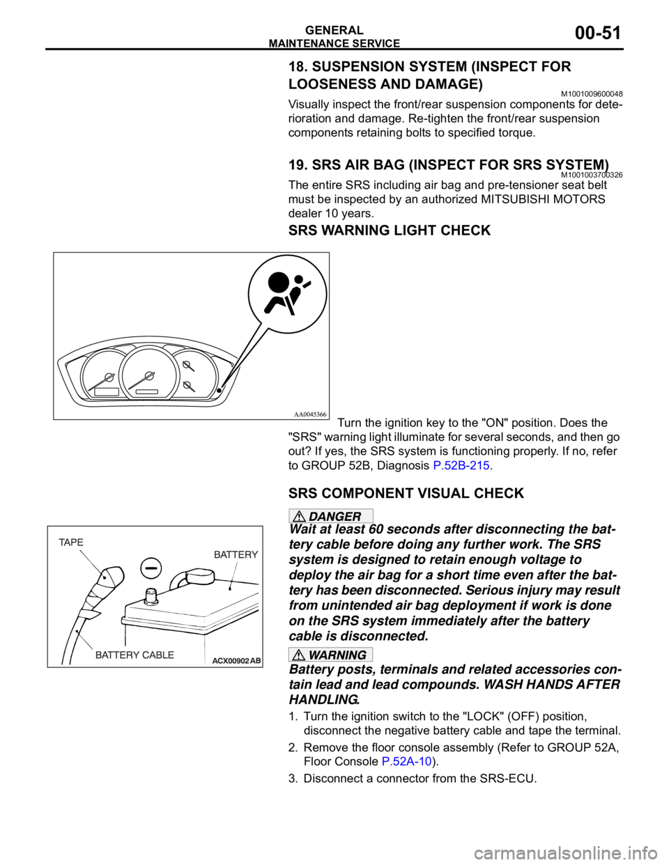
Turn the ignition key to the "ON" position. Does the
"SRS" warning light illuminate for several seconds, and then go
out? If yes, the SRS system is functioning properly. If no, refer
to GROUP 52B, Diagnosis P.52B-215.
SRS COMPONENT VISUAL CHECK
Wait at least 60 seconds after disconnecting the bat-
tery cable before doing any further work. The SRS
system is designed to retain enough voltage to
deploy the air bag for a short time even after the bat-
tery has been disconnected. Serious injury may result
from unintended air bag deployment if work is done
on the SRS system immediately after the battery
cable is disconnected.
Battery posts, terminals and related accessories con-
tain lead and lead compounds. WASH HANDS AFTER
HANDLING.
1. Turn the ignition switch to the "LOCK" (OFF) position,
disconnect the negative battery cable and tape the terminal.
2. Remove the floor console assembly (Refer to GROUP 52A,
Floor Console P.52A-10).
3. Disconnect a connector from the SRS-ECU.
Page 1276 of 1500

MAINTENANCE SERVICE
GENERAL00-55
The SRS may not activate if any of the above compo-
nents are not installed properly, which could result in
serious injury or death to the vehicle's driver and
front passenger.
11.Check the steering wheel for excessive free play.
Replace any part if it fails visual inspection (Refer to
GROUP 52B, Air Bag Module and Clock Spring P.52B-237).
FRONT SEATBACK ASSEMBLY WITH
SIDE-AIRBAG MODULE
If any improper part is found during the following
inspection, replace the front seatback assembly
with a new one.
Dispose of the old one according to the specified
procedure (Refer to GROUP 52B, Air Bag Module
Disposal Procedures P.52B-254).
Never attempt to measure the circuit resistance of
the air bag module (squib) even if you are using
the specified tester. If the circuit resistance is mea-
sured with a tester, accidental air bag deployment
will result in serious personal injury.
1. Check the air bag module deployment section for dents or
deformation.
2. Check the connector for damage; Check the terminals for
deformation; and check the harness for binding.
Replace the front seat if it fails the visual checks above
(Refer to GROUP 52A, Front Seat P.52A-33).
SEAT BELT WITH PRE-TENSIONER
If the seat belt pre-tensioner is not installed
securely and correctly, the seat belt pre-tensioner
may not operate normally.
If a dent, crack, deformation or rust is detected,
replace with a new seat belt pre-tensioner.
1. Check the seat belt pre-tensioner for dents or deformation.
2. Check that the seat belt pre-tensioner is installed correctly to
the vehicle body.
Replace the seat belt pre-tensioner if it fails the visual
checks above (Refer to GROUP 52B, Seat Belt
Pre-tensioner P.52B-250).
Page 1322 of 1500
TRACTION CONTROL SYSTEM (TCL) DIAGNOSIS
TRACTION CONTROL SYSTEM (TCL)13C-43
(7) The recommended Supply Voltage at terminals 16, 9, 6,
and 8 are:
Set value: 10.0Volts - 14.5Volts
Q: Is the supply voltage within the set value?
YES : Check wheel speed sensor signal at ABS-ECU using
an oscillopscope
NO :
Refer to Power supply systemP.35B-63
Refer to Motor supply systemP.35B-48
Refer to Valve relay systemP.35B-56
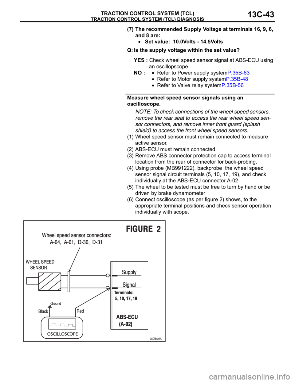
Measure wheel speed sensor signals using an
oscilloscope.
NOTE: To check connections of the wheel speed sensors,
remove the rear seat to access the rear wheel speed sen-
sor connectors, and remove inner front guard (splash
shield) to access the front wheel speed sensors.
(1) Wheel speed sensor must remain connected to measure
active sensor.
(2) ABS-ECU must remain connected.
(3) Remove ABS connector protection cap to access terminal
location from the rear of connector for back-probing.
(4) Using probe (MB991222), backprobe the wheel speed
sensor signal circuit terminals (5, 10, 17, 19), and check
individually at the ABS-ECU connector A-02
(5) The wheel to be tested must be free to turn by hand or be
driven by brake dynamometer
(6) Connect oscilloscope (as per figure 2) shows, to the
appropriate terminal positions and check sensor operation
individually with scope.
Page 1429 of 1500
FRONT AXLE HUB ASSEMBLY
FRONT AXLE26-12
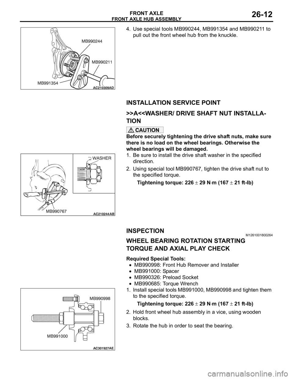
4. Use special tools MB990244, MB991354 and MB990211 to
pull out the front wheel hub from the knuckle.
INSTALLATION SERVICE POINT
.
>>A<
TION
Before securely tightening the drive shaft nuts, make sure
there is no load on the wheel bearings. Otherwise the
wheel bearings will be damaged.
1. Be sure to install the drive shaft washer in the specified
direction.
2. Using special tool MB990767, tighten the drive shaft nut to
the specified torque.
Tightening torque: 226
29 Nm (167 21 ft-lb)
INSPECTIONM1261001800264
WHEEL BEARING ROTATION STARTING
TORQUE AND AXIAL PLAY CHECK
Required Special Tools:
MB990998: Front Hub Remover and Installer
MB991000: Spacer
MB990326: Preload Socket
MB990685: Torque Wrench
1. Install special tools MB991000, MB990998 and tighten them
to the specified torque.
Tightening torque: 226
29 Nm (167 21 ft-lb)
2. Hold front wheel hub assembly in a vice, using wooden
blocks.
3. Rotate the hub in order to seat the bearing.
Page 1450 of 1500
REAR AXLE DIAGNOSIS
REAR AXLE27-3
SYMPTOM PROCEDURESM1271004400222
INSPECTION PROCEDURE 1: Abnormal Noise
DIAGNOSIS
STEP 1. Check the rear hub assembly installation bolts for
looseness.
Q: Are the rear hub assembly installation bolts loosened?
YES : Tighten the rear hub assembly installation bolts to the
specified torque 73
7 Nm (54 5 ft-lb). Then go to
St e p 4 .
NO : Go to Step 2.
STEP 2. Check the wheel bearing end play.
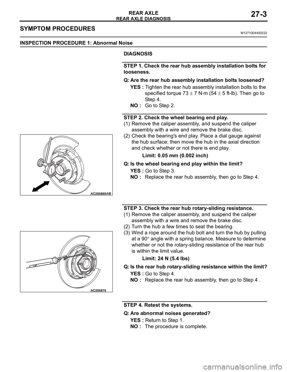
(1) Remove the caliper assembly, and suspend the caliper
assembly with a wire and remove the brake disc.
(2) Check the bearing's end play. Place a dial gauge against
the hub surface; then move the hub in the axial direction
and check whether or not there is end play.
Limit: 0.05 mm (0.002 inch)
Q: Is the wheel bearing end play within the limit?
YES : Go to Step 3.
NO : Replace the rear hub assembly, then go to Step 4.
STEP 3. Check the rear hub rotary-sliding resistance.
(1) Remove the caliper assembly, and suspend the caliper
assembly with a wire and remove the brake disc.
(2) Turn the hub a few times to seat the bearing.
(3) Wind a rope around the hub bolt and turn the hub by pulling
at a 90
angle with a spring balance. Measure to determine
whether or not the rotary-sliding resistance of the rear hub
is within the limit value.
Limit: 24 N (5.4 lbs)
Q: Is the rear hub rotary-sliding resistance within the limit?
YES : Go to Step 4.
NO : Replace the rear hub assembly, then go to Step 4 .
STEP 4. Retest the systems.
Q: Are abnormal noises generated?
YES : Return to Step 1.
NO : The procedure is complete.
Page 1452 of 1500
ON-VEHICLE SERVICE
REAR AXLE27-5
REAR HUB ROTARY-SLIDING RESISTANCE
CHECK
M1271001100266
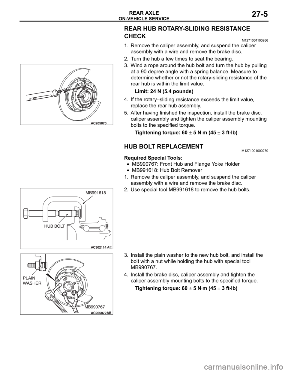
1. Remove the caliper assembly, and suspend the caliper
assembly with a wire and remove the brake disc.
2. Turn the hub a few times to seat the bearing.
3. Wind a rope around the hub bolt and turn the hub by pulling
at a 90 degree angle with a spring balance. Measure to
determine whether or not the rotary-sliding resistance of the
rear hub is within the limit value.
Limit: 24 N (5.4 pounds)
4. If the rotary
sliding resistance exceeds the limit value,
replace the rear hub assembly.
5. After having finished the inspection, install the brake disc,
caliper assembly and tighten the caliper assembly mounting
bolts to the specified torque.
Tightening torque: 60
5 Nm (45 3 ft-lb)
HUB BOLT REPLACEMENTM1271001000270
Required Special Tools:
MB990767: Front Hub and Flange Yoke Holder
MB991618: Hub Bolt Remover
1. Remove the caliper assembly, and suspend the caliper
assembly with a wire and remove the brake disc.
2. Use special tool MB991618 to remove the hub bolts.
3. Install the plain washer to the new hub bolt, and install the
bolt with a nut while holding the hub with special tool
MB990767.
4. Install the brake disc, caliper assembly and tighten the
caliper assembly mounting bolts to the specified torque.
Tightening torque: 60
5 Nm (45 3 ft-lb)