Page 691 of 1500
SEAT BELT WARNING TONE ALARM
CIRCUIT DIAGRAMS90-114
Page 852 of 1500

HEATER UNIT, HEATER CORE, BLOWER ASSEMBLY AND EVAPORATOR UNIT
HEATER, AIR CONDITIONING AND VENTILATION55-151
HEATER UNIT, HEATER CORE, BLOWER ASSEMBLY AND
EVAPORATOR UNIT
REMOVAL AND INSTALLATIONM1552021400012
Before removing the front seat assembly, refer to GROUP 52B, Service Precautions
P.52B-16 and Air Bag Module and Clock Spring P.52B-237.
Pre-removal and Post-installation Operation
Refrigerant draining and Refilling (Refer to Charging and
Discharging P.55-142).
Engine coolant Draining and Refilling (Refer to GROUP
00, Engine coolant P.00-47).
Instrument Panel Removal and Installation (Refer to
GROUP 52A, Instrument Panel P.52A-4).
Steering Column Shaft Assembly Removal and Installa-
tion (Refer to GROUP 37A, Steering ShaftP.37-25).
Floor Console Removal and Installation (Refer to GROUP
52A, Floor Console P.52A-10).
Front Seat Assembly Removal and Installation (Refer to
GROUP 52A, Front Seat P.52A-21).
² Strut Tower Bar (Refer to GROUP 42, Removal And
InstallationP.42-12.)
REMOVAL STEPS
BATTERY
AIR CLEANER BODY (REFER TO
GROUP 15, AIR CLEANER
P.15-4.)
1. HEATER HOSE CONNECTION
<>2. SUCTION PIPE CONNECTION
<>3. LIQUID PIPE CONNECTION
4. O-RING
REAR HEATER DUCT A AND B
(REFER TO P.55-175.)
5. JUNCTION BLOCKREMOVAL STEPS (Continued)
Page 876 of 1500
DUCTS
HEATER, AIR CONDITIONING AND VENTILATION55-175
DUCTS
REMOVAL AND INSTALLATIONM1553001000275
DEFROSTER NOZZLE AND
DISTRIBUTION DUCT REMOVAL
STEPS
INSTRUMENT PANEL (REFER TO
GROUP 52A P.52A-4).
1. VENTILATOR AIR DISTRIBUTION
DUCT
2. SIDE DEFROSTER DUCT
3. DEFROSTER NOZZLE
FOOT DUCT AND REAR HEATER
DUCT REMOVAL STEPS
FRONT SEAT ASSEMBLY
(REFER TO GROUP 52A, FRONT
SEAT ASSEMBLY P.52A-21).
FRONT SCUFF PLATE, COWL
SIDE TRIM (REFER TO GROUP
52A, TRIMS P.52A-11.)
FLOOR CARPET PEELING
FLOOR CONSOLE ASSEMBLY
(REFER TO GROUP 52A, FLOOR
CONSOLE ASSEMBLY P.52A-10.)
TRUNK LID RELEASE HANDLE
COVER (REFER TO GROUP 42,
TRUNK LID P.42-63.)
ACCELERATOR STOPPER
(REFER TO GROUP 17,
ACCELERATOR CABLE AND
PEDAL P.17-9.)
4. REAR HEATER DUCT A
5. REAR HEATER DUCT BFOOT DUCT AND REAR HEATER
DUCT REMOVAL STEPS
Page 961 of 1500

GENERAL DESCRIPTION
INTAKE AND EXHAUST15-2
GENERAL DESCRIPTIONM1151000100446
The exhaust pipe is divided into four parts.
INTAKE AND EXHAUST DIAGNOSIS
INTRODUCTIONM1151006900321
Intake leaks usually create driveability issues that
are not obviously related to the intake system.
Exhaust leaks or abnormal noise is caused by
cracks, gaskets and fittings, or by exhaust pipe or
muffler damage due to impacts during travel. The
exhaust leaks from these sections and causes the
exhaust noise to increase. There may be cases
when the system contacts the body and vibration
noise is generated.
TROUBLESHOOTING STRATEGYM1151007000321
Use these steps to plan your diagnostic strategy. If
you follow them carefully, you will be sure that you
have exhausted most of the possible ways to find an
intake or exhaust system fault.
1. Gather information from the customer.2. Verify that the condition described by the
customer exists.
3. Find the malfunction by following the Symptom
Chart.
4. Verify malfunction is eliminated.
SYMPTOM CHARTM1151007100328
SYMPTOM PROCEDURES
INSPECTION PROCEDURE 1: Exhaust Leakage
DIAGNOSIS
STEP 1. Start the engine. Have an assistant stay
in the driver’s seat. Raise the vehicle on a hoist.
Have the assistant rev the engine while
searching for exhaust leaks.
Q: Is the exhaust leaking?
YES :
Go to Step 2.
NO : The procedure is complete.
STEP 2. Check the gasket for cracks, damage.
Q: Is the gasket damaged?
YES :
Replace the gasket, then go Step 1.
NO : Go to Step 3.
STEP 3. Check for loose coupling sections.
Q: Are there any loose each sections?
YES :
Tighten, then go to Step 1.
NO : There is no action to be taken. SYMPTOM INSPECTION PROCEDURE REFERENCE PAGE
Exhaust Leakage 1
P.15-2
Abnormal Noise 2
P.15-3
Page 962 of 1500

SPECIAL TOOLS
INTAKE AND EXHAUST15-3
INSPECTION PROCEDURE 2: Abnormal Noise
DIAGNOSIS
STEP 1. Start the engine. Have an assistant stay
in the drivers seat. Raise the vehicle on a hoist.
Have the assistant rev the engine while
searching for exhaust leaks.
Q: Is any abnormal noise generated?
YES :
Go to Step 2.
NO : The procedure is complete.
STEP 2. Check for missing parts in the muffler.
Tap the muffler lightly to check for loose baffles,
etc.
Q: Are there any missing parts in the muffler?
YES :
Replace, then go to Step 1.
NO : Go to Step 3.
STEP 3. Check the hanger for cracks.
Q: Is the hanger cracked?
YES :
Replace, then go to Step 1.
NO : Go to Step 4.
STEP 4. Check for interference of the pipes and
muffler with the body.
Q: Are the pipes and muffler interfering with the
body?
YES :
Repair, then go to Step 1.
NO : Go to Step 5.
STEP 5. Check the heat protectors.
Q: Are any heat protectors loose or damaged?
YES :
Tighten or replace, then go to Step 1.
NO : Go to Step 6.
STEP 6. Check the pipes and muffler for damage.
Q: Are the pipes and muffler damaged?
YES :
Replace, then go to Step 1.
NO : There is no action to be taken.
SPECIAL TOOLSM1151000600429
TOOL TOOL NUMBER AND
NAMESUPERSESSION APPLICATION
MD998412
GuideMD998412 Installation of intake
manifold plenum
MB991953
Oxygen sensor wrench- Removal and installation
of heated oxygen sensor
MD998770
Oxygen sensor wrenchMD998770-01 or General
service toolRemoval and installation
of heated oxygen sensor
Page 1008 of 1500

IGNITION SYSTEM
ENGINE ELECTRICAL16-31
ON-VEHICLE SERVICE
KNOCK CONTROL SYSTEM CHECKM1163001800081
Check the knock sensor circuit if diagnostic trouble code, No.
P0325 is shown.
Refer to GROUP 13B, Multiport Fuel Injection (MPI)
Multiport
Fuel Injection (MPI) Diagnosis
Diagnostic Trouble Code Pro-
cedures
DTC P0325 : Knock Sensor Circuit 13A-346.
IGNITION COIL CHECK M1163001200380
Check by the following procedure, and replace the coil if there
is a malfunction.
.
PRIMARY COIL AND IGNITION POWER
TRANSISTOR CONTINUITY CHECK
NOTE: No test can be performed on the Primary side of coil.
.
SECONDARY COIL CHECK
NOTE: It is impossible to check the secondary coil through the
continuity check as a diode is integrated in the secondary coil
circuit of this ignition coil. Accordingly, check the secondary coil
in the following procedure.
1. Disconnect the ignition coil connector.
2. Remove the ignition coil and install a new spark plug to the
ignition coil.
3. Connect the ignition coil connector.
4. Disable vehicle fuel pump by removing fuel pump relay or
disconnecting fuel pump connector D-18 (under rear seat).
5. Ground the side electrode of the spark plug and crank the
engine.
6. Check that spark is produced between the electrodes of the
spark plug.
7. If no spark is produced, replace the ignition coil with a new
one and recheck.
8. If spark is produced with the new ignition coil, replace the
old one as it is faulty. If no spark is produced again, the
ignition circuit is suspected as faulty. Check the ignition
circuit.
Page 1131 of 1500

TRUNK LID
BODY42-64
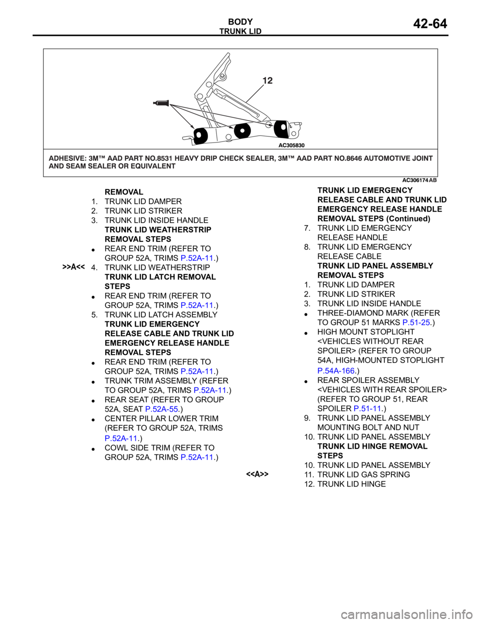
REMOVAL
1. TRUNK LID DAMPER
2. TRUNK LID STRIKER
3. TRUNK LID INSIDE HANDLE
TRUNK LID WEATHERSTRIP
REMOVAL STEPS
REAR END TRIM (REFER TO
GROUP 52A, TRIMS P.52A-11.)
>>A<<4. TRUNK LID WEATHERSTRIP
TRUNK LID LATCH REMOVAL
STEPS
REAR END TRIM (REFER TO
GROUP 52A, TRIMS P.52A-11.)
5. TRUNK LID LATCH ASSEMBLY
TRUNK LID EMERGENCY
RELEASE CABLE AND TRUNK LID
EMERGENCY RELEASE HANDLE
REMOVAL STEPS
REAR END TRIM (REFER TO
GROUP 52A, TRIMS P.52A-11.)
TRUNK TRIM ASSEMBLY (REFER
TO GROUP 52A, TRIMS P.52A-11.)
REAR SEAT (REFER TO GROUP
52A, SEAT P.52A-55.)
CENTER PILLAR LOWER TRIM
(REFER TO GROUP 52A, TRIMS
P.52A-11.)
COWL SIDE TRIM (REFER TO
GROUP 52A, TRIMS P.52A-11.)7. TRUNK LID EMERGENCY
RELEASE HANDLE
8. TRUNK LID EMERGENCY
RELEASE CABLE
TRUNK LID PANEL ASSEMBLY
REMOVAL STEPS
1. TRUNK LID DAMPER
2. TRUNK LID STRIKER
3. TRUNK LID INSIDE HANDLE
THREE-DIAMOND MARK (REFER
TO GROUP 51 MARKS P.51-25.)
HIGH MOUNT STOPLIGHT
SPOILER> (REFER TO GROUP
54A, HIGH-MOUNTED STOPLIGHT
P.54A-166.)
REAR SPOILER ASSEMBLY
(REFER TO GROUP 51, REAR
SPOILER P.51-11.)
9. TRUNK LID PANEL ASSEMBLY
MOUNTING BOLT AND NUT
10. TRUNK LID PANEL ASSEMBLY
TRUNK LID HINGE REMOVAL
STEPS
10. TRUNK LID PANEL ASSEMBLY
<>11. TRUNK LID GAS SPRING
12. TRUNK LID HINGETRUNK LID EMERGENCY
RELEASE CABLE AND TRUNK LID
EMERGENCY RELEASE HANDLE
REMOVAL STEPS (Continued)
Page 1186 of 1500

ON-VEHICLE SERVICE
BASIC BRAKE SYSTEM35A-21
After a new brake disc is installed, always grind the
brake disc with an on-the-car type brake lathe. If this
step is not carried out, the brake disc run-out exceeds
the specified value, resulting in judder.
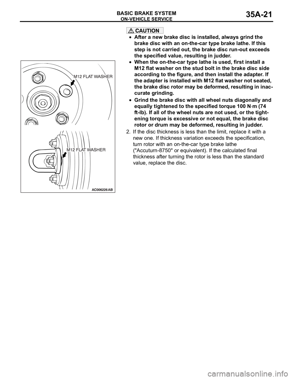
When the on-the-car type lathe is used, first install a
M12 flat washer on the stud bolt in the brake disc side
according to the figure, and then install the adapter. If
the adapter is installed with M12 flat washer not seated,
the brake disc rotor may be deformed, resulting in inac-
curate grinding.
Grind the brake disc with all wheel nuts diagonally and
equally tightened to the specified torque 100 N
m (74
ft-lb). If all of the wheel nuts are not used, or the tight-
ening torque is excessive or not equal, the brake disc
rotor or drum may be deformed, resulting in judder.
2. If the disc thickness is less than the limit, replace it with a
new one. If thickness variation exceeds the specification,
turn rotor with an on-the-car type brake lathe
("Accuturn-8750" or equivalent). If the calculated final
thickness after turning the rotor is less than the standard
value, replace the disc.
.