2005 MITSUBISHI 380 seat
[x] Cancel search: seatPage 1188 of 1500
ON-VEHICLE SERVICE
BASIC BRAKE SYSTEM35A-23
After a new brake disc is installed, always grind the
brake disc with an on-the-car type brake lathe. If this
step is not carried out, the brake disc run-out exceeds
the specified value, resulting in judder.
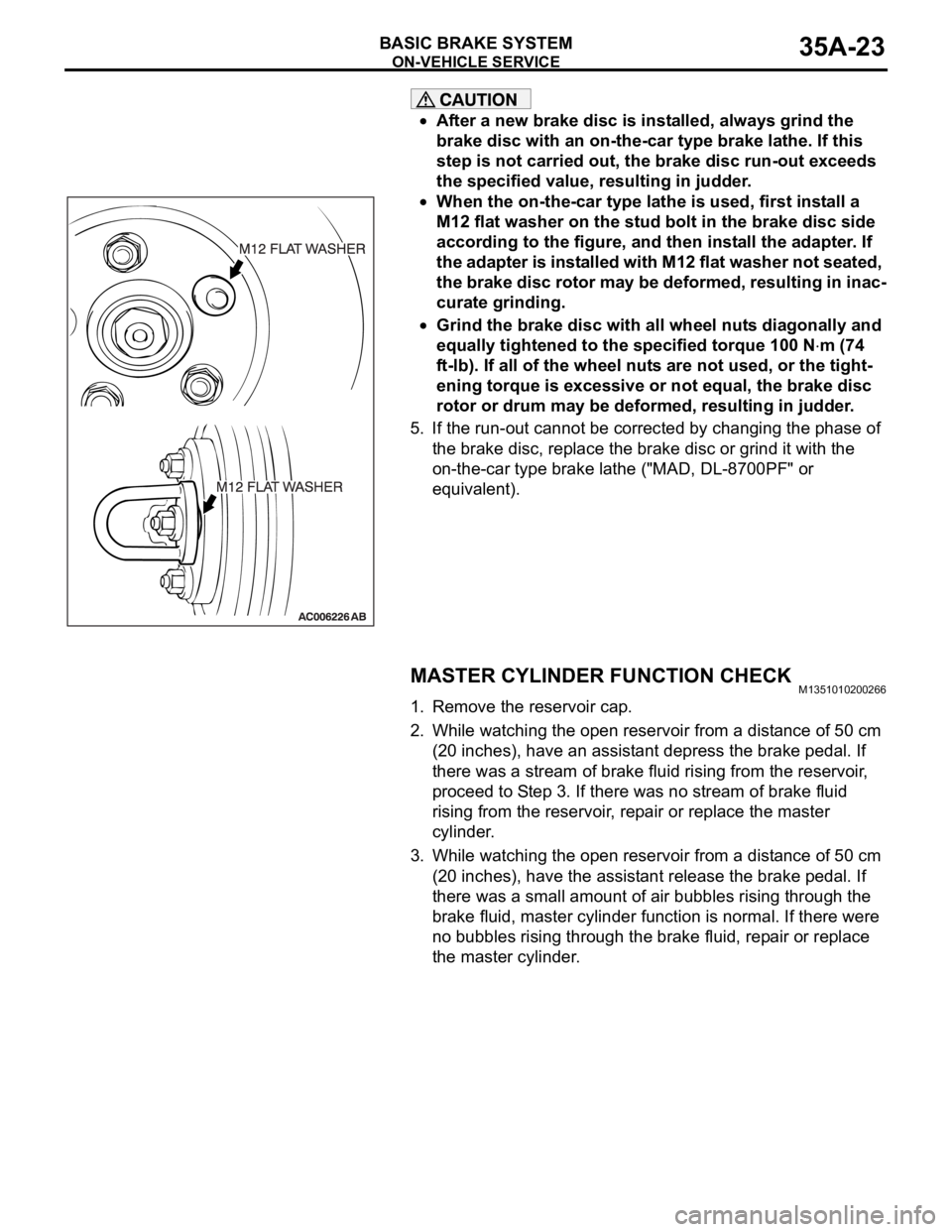
When the on-the-car type lathe is used, first install a
M12 flat washer on the stud bolt in the brake disc side
according to the figure, and then install the adapter. If
the adapter is installed with M12 flat washer not seated,
the brake disc rotor may be deformed, resulting in inac-
curate grinding.
Grind the brake disc with all wheel nuts diagonally and
equally tightened to the specified torque 100 N
m (74
ft-lb). If all of the wheel nuts are not used, or the tight-
ening torque is excessive or not equal, the brake disc
rotor or drum may be deformed, resulting in judder.
5. If the run-out cannot be corrected by changing the phase of
the brake disc, replace the brake disc or grind it with the
on-the-car type brake lathe ("MAD, DL-8700PF" or
equivalent).
MASTER CYLINDER FUNCTION CHECKM1351010200266
1. Remove the reservoir cap.
2. While watching the open reservoir from a distance of 50 cm
(20 inches), have an assistant depress the brake pedal. If
there was a stream of brake fluid rising from the reservoir,
proceed to Step 3. If there was no stream of brake fluid
rising from the reservoir, repair or replace the master
cylinder.
3. While watching the open reservoir from a distance of 50 cm
(20 inches), have the assistant release the brake pedal. If
there was a small amount of air bubbles rising through the
brake fluid, master cylinder function is normal. If there were
no bubbles rising through the brake fluid, repair or replace
the master cylinder.
Page 1208 of 1500
36-1
GROUP 36
PARKING BRAKES
CONTENTS
GENERAL DESCRIPTION. . . . . . . . .36-2
PARKING BRAKE DIAGNOSIS . . . .36-2
INTRODUCTION. . . . . . . . . . . . . . . . . . . . . 36-2
TROUBLESHOOTING STRATEGY . . . . . . 36-2
SYMPTOM CHART. . . . . . . . . . . . . . . . . . . 36-2
SYMPTOM PROCEDURES . . . . . . . . . . . . 36-3
ON-VEHICLE SERVICE . . . . . . . . . . .36-3
PARKING BRAKE LEVER STROKE CHECK
AND ADJUSTMENT . . . . . . . . . . . . . . . . . . 36-3
PARKING BRAKE SWITCH CHECK . . . . . 36-5
PARKING BRAKE LINING SEATING
PROCEDURE . . . . . . . . . . . . . . . . . . . . . . . 36-5
PARKING BRAKE LEVER . . . . . . . . .36-6
REMOVAL AND INSTALLATION . . . . . . . . 36-6
PARKING BRAKE CABLE . . . . . . . . .36-7
REMOVAL AND INSTALLATION . . . . . . . . 36-7
PARKING BRAKE LINING AND
DRUM . . . . . . . . . . . . . . . . . . . . . . . . .36-8
REMOVAL AND INSTALLATION . . . . . . . . 36-8
INSPECTION. . . . . . . . . . . . . . . . . . . . . . . . 36-11
SPECIFICATIONS . . . . . . . . . . . . . . .36-12
FASTENER TIGHTENING SPECIFICATIONS36-12
SERVICE SPECIFICATIONS . . . . . . . . . . . 36-12
LUBRICANT . . . . . . . . . . . . . . . . . . . . . . . . 36-12
Page 1210 of 1500
ON-VEHICLE SERVICE
PARKING BRAKES36-3
SYMPTOM PROCEDURES
INSPECTION PROCEDURE 1: Insufficient Parking Brake Function
DIAGNOSIS
STEP 1. Check the excessive parking brake lever
stroke.
Refer to P.36-3.
Q: Is the parking brake lever stroke adjusted
properly?
YES :
Go to Step 2.
NO : Adjust the parking brake lever stroke or
check the parking brake cable routing. Then
go to Step 5.
STEP 2. Check the parking brake cable for
sticking.
Q: Is the parking brake cable stuck?
YES :
Replace the cable. Then go to Step 5.
NO : Go to Step 3.
STEP 3. Check the brake lining and brake drum
for wear.
Refer to P.36-11.
Q: Is the brake lining thickness or brake drum inside
diameter outside of specification?
YES :
Replace the rear brake shoe assembly or
rear brake disc (Refer to P.36-8). Then go to
Step 5.
NO : Go to Step 4.
STEP 4. Check for oil, water, etc., on the lining
contact surfaces.
Q: Is oil, water, etc., on the lining contact surface?
YES :
Replace the part and determine and repair
source/cause of foreign material. Then go to
St e p 5.
NO : Carry out the parking brake lining seating
(Refer to P.36-5) and then go to Step 5.
STEP 5. Retest the system.
Q: Is the malfunction eliminated?
YES :
The procedure is complete.
NO : Recheck from Step 1.
ON-VEHICLE SERVICE
PARKING BRAKE LEVER STROKE CHECK AND
ADJUSTMENT
M1361000900362
1. Pull the parking brake lever with a force of approximately
200 N (45 pounds) and count the number of notches.
Standard value: 5
7 notches
2. If the parking brake lever stroke is not within the standard
value, adjust as described below.
(1) Release the parking brake.
Page 1212 of 1500
ON-VEHICLE SERVICE
PARKING BRAKES36-5
PARKING BRAKE SWITCH CHECKM1361003300411
1. Remove the floor console. (Refer to GROUP 52A, Floor
Console P.52A-10.)
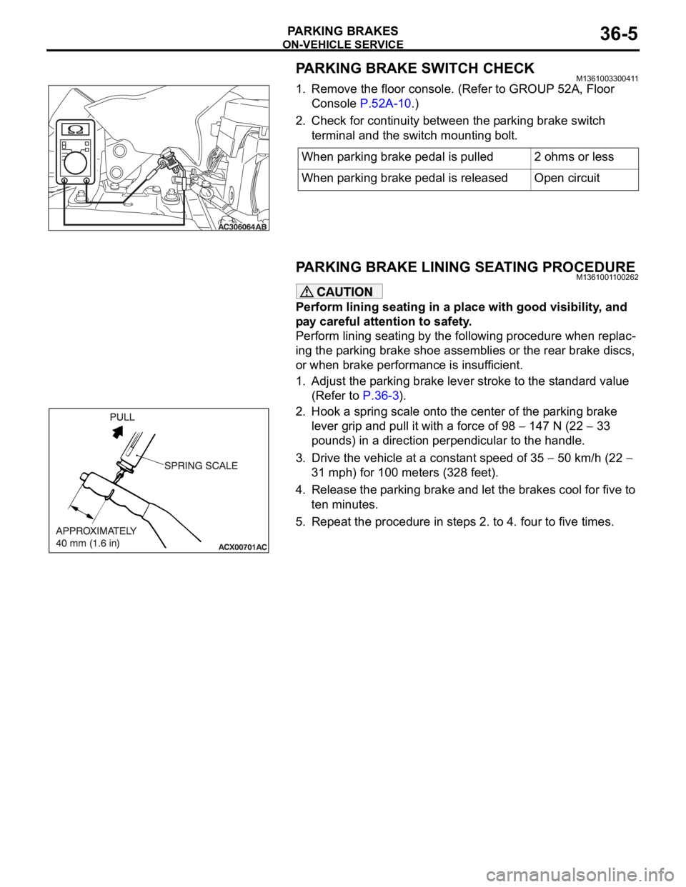
2. Check for continuity between the parking brake switch
terminal and the switch mounting bolt.
PARKING BRAKE LINING SEATING PROCEDUREM1361001100262
Perform lining seating in a place with good visibility, and
pay careful attention to safety.
Perform lining seating by the following procedure when replac-
ing the parking brake shoe assemblies or the rear brake discs,
or when brake performance is insufficient.
1. Adjust the parking brake lever stroke to the standard value
(Refer to P.36-3).
2. Hook a spring scale onto the center of the parking brake
lever grip and pull it with a force of 98
147 N (22 33
pounds) in a direction perpendicular to the handle.
3. Drive the vehicle at a constant speed of 35
50 km/h (22
31 mph) for 100 meters (328 feet).
4. Release the parking brake and let the brakes cool for five to
ten minutes.
5. Repeat the procedure in steps 2. to 4. four to five times.When parking brake pedal is pulled 2 ohms or less
When parking brake pedal is released Open circuit
Page 1215 of 1500
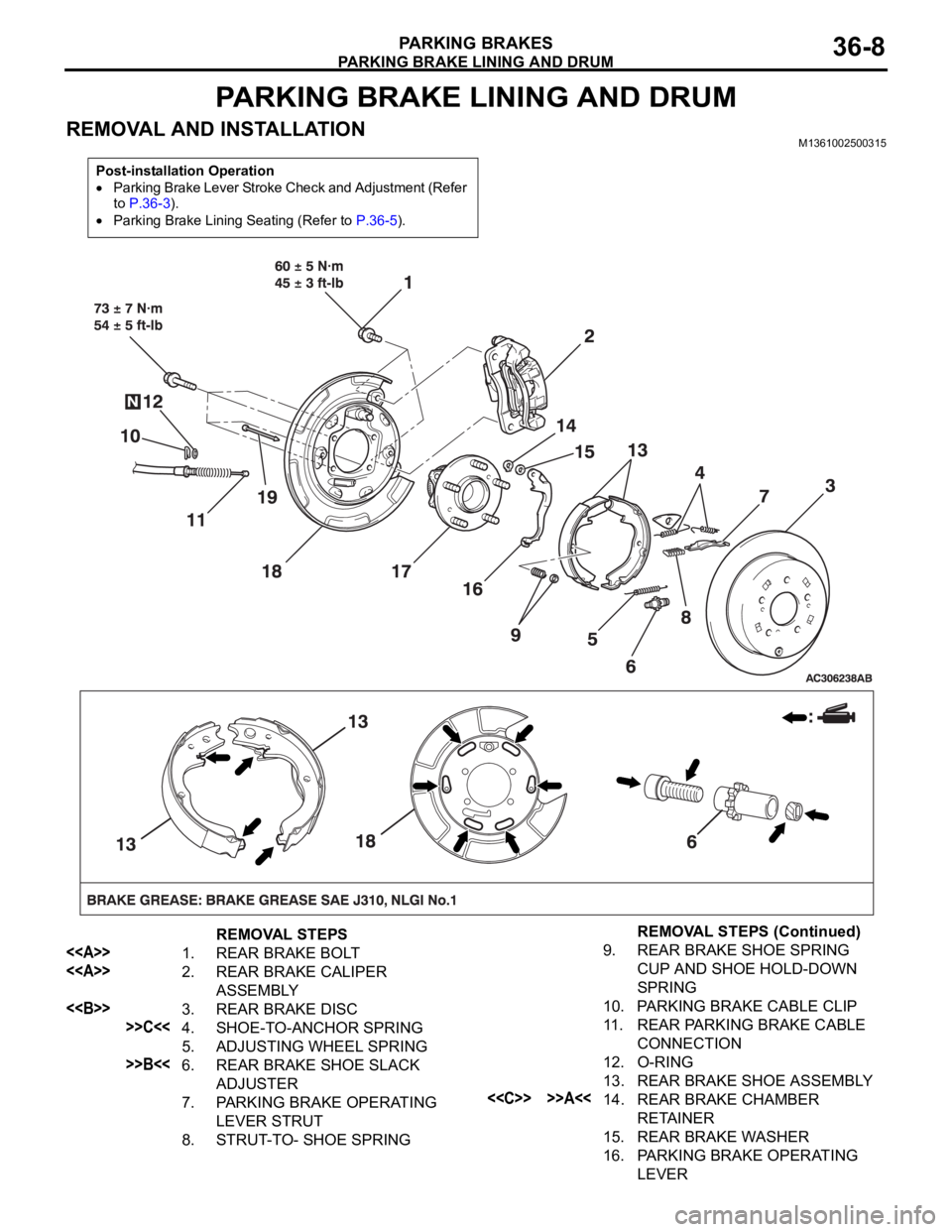
PARKING BRAKE LINING AND DRUM
PARKING BRAKES36-8
PARKING BRAKE LINING AND DRUM
REMOVAL AND INSTALLATIONM1361002500315
Post-installation Operation
Parking Brake Lever Stroke Check and Adjustment (Refer
to P.36-3).
Parking Brake Lining Seating (Refer to P.36-5).
REMOVAL STEPS
<> 1. REAR BRAKE BOLT
<> 2. REAR BRAKE CALIPER
ASSEMBLY
<> 3. REAR BRAKE DISC
>>C<<4. SHOE-TO-ANCHOR SPRING
5. ADJUSTING WHEEL SPRING
>>B<<6. REAR BRAKE SHOE SLACK
ADJUSTER
7. PARKING BRAKE OPERATING
LEVER STRUT
8. STRUT-TO- SHOE SPRING
9. REAR BRAKE SHOE SPRING
CUP AND SHOE HOLD-DOWN
SPRING
10. PARKING BRAKE CABLE CLIP
11. REAR PARKING BRAKE CABLE
CONNECTION
12. O-RING
13. REAR BRAKE SHOE ASSEMBLY
<
RETAINER
15. REAR BRAKE WASHER
16. PARKING BRAKE OPERATING
LEVER
REMOVAL STEPS (Continued)
Page 1242 of 1500
VEHICLE IDENTIFICATION
GENERAL00-21
OPTION CODES (380 Series)
EXPORT CODES
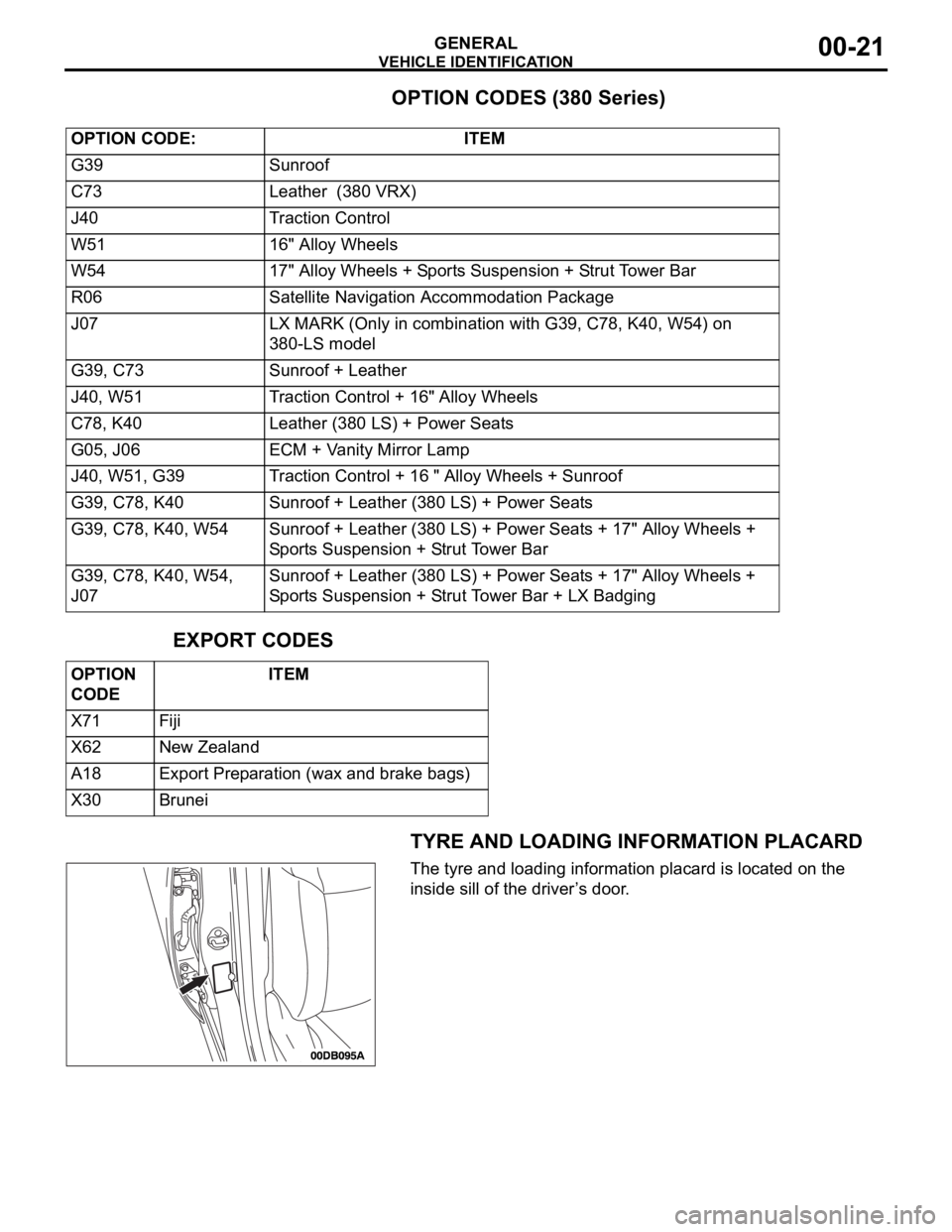
TYRE AND LOADING INFORMATION PLACARD
The tyre and loading information placard is located on the
inside sill of the driver’s door. OPTION CODE: ITEM
G39 Sunroof
C73 Leather (380 VRX)
J40 Traction Control
W51 16" Alloy Wheels
W54 17" Alloy Wheels + Sports Suspension + Strut Tower Bar
R06 Satellite Navigation Accommodation Package
J07 LX MARK (Only in combination with G39, C78, K40, W54) on
380-LS model
G39, C73 Sunroof + Leather
J40, W51 Traction Control + 16" Alloy Wheels
C78, K40 Leather (380 LS) + Power Seats
G05, J06 ECM + Vanity Mirror Lamp
J40, W51, G39 Traction Control + 16 " Alloy Wheels + Sunroof
G39, C78, K40 Sunroof + Leather (380 LS) + Power Seats
G39, C78, K40, W54 Sunroof + Leather (380 LS) + Power Seats + 17" Alloy Wheels +
Sports Suspension + Strut Tower Bar
G39, C78, K40, W54,
J07Sunroof + Leather (380 LS) + Power Seats + 17" Alloy Wheels +
Sports Suspension + Strut Tower Bar + LX Badging
OPTION
CODE ITEM
X71 Fiji
X62 New Zealand
A18 Export Preparation (wax and brake bags)
X30 Brunei
Page 1243 of 1500
PRECAUTIONS BEFORE SERVICE
GENERAL00-22
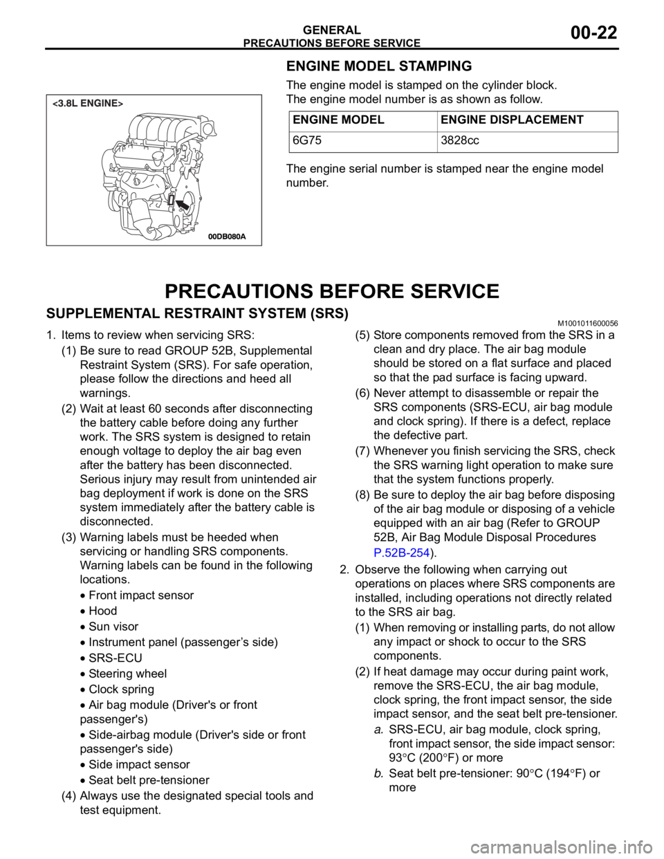
ENGINE MODEL STAMPING
The engine model is stamped on the cylinder block.
The engine model number is as shown as follow.
The engine serial number is stamped near the engine model
number.
PRECAUTIONS BEFORE SERVICE
SUPPLEMENTAL RESTRAINT SYSTEM (SRS)M1001011600056
1. Items to review when servicing SRS:
(1) Be sure to read GROUP 52B, Supplemental
Restraint System (SRS). For safe operation,
please follow the directions and heed all
warnings.
(2) Wait at least 60 seconds after disconnecting
the battery cable before doing any further
work. The SRS system is designed to retain
enough voltage to deploy the air bag even
after the battery has been disconnected.
Serious injury may result from unintended air
bag deployment if work is done on the SRS
system immediately after the battery cable is
disconnected.
(3) Warning labels must be heeded when
servicing or handling SRS components.
Warning labels can be found in the following
locations.
Front impact sensor
Hood
Sun visor
Instrument panel (passenger ’s side)
SRS-ECU
Steering wheel
Clock spring
Air bag module (Driver's or front
passenger's)
Side-airbag module (Driver's side or front
passenger's side)
Side impact sensor
Seat belt pre-tensioner
(4) Always use the designated special tools and
test equipment.(5) Store components removed from the SRS in a
clean and dry place. The air bag module
should be stored on a flat surface and placed
so that the pad surface is facing upward.
(6) Never attempt to disassemble or repair the
SRS components (SRS-ECU, air bag module
and clock spring). If there is a defect, replace
the defective part.
(7) Whenever you finish servicing the SRS, check
the SRS warning light operation to make sure
that the system functions properly.
(8) Be sure to deploy the air bag before disposing
of the air bag module or disposing of a vehicle
equipped with an air bag (Refer to GROUP
52B, Air Bag Module Disposal Procedures
P.52B-254).
2. Observe the following when carrying out
operations on places where SRS components are
installed, including operations not directly related
to the SRS air bag.
(1) When removing or installing parts, do not allow
any impact or shock to occur to the SRS
components.
(2) If heat damage may occur during paint work,
remove the SRS-ECU, the air bag module,
clock spring, the front impact sensor, the side
impact sensor, and the seat belt pre-tensioner.
a.SRS-ECU, air bag module, clock spring,
front impact sensor, the side impact sensor:
93
C (200F) or more
b.Seat belt pre-tensioner: 90
C (194F) or
more ENGINE MODEL ENGINE DISPLACEMENT
6G75 3828cc
Page 1252 of 1500
GENERAL DATA AND SPECIFICATIONS
GENERAL00-31
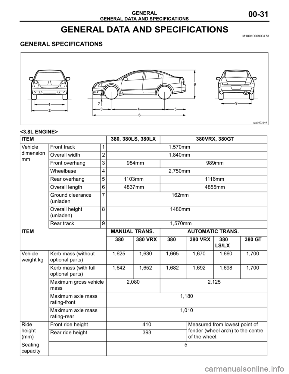
GENERAL DATA AND SPECIFICATIONSM1001000900473.
GENERAL SPECIFICATIONS
<3.8L ENGINE>
ITEM 380, 380LS, 380LX 380VRX, 380GT
Vehicle
dimension
mmFront track 1 1,570mm
Overall width 2 1,840mm
Front overhang 3 984mm 989mm
Wheelbase 4 2,750mm
Rear overhang 5 1103mm 1116mm
Overall length 6 4837mm 4855mm
Ground clearance
(unladen7 162mm
Overall height
(unladen)8 1480mm
Rear track 9 1,570mm
ITEM MANUAL TRANS. AUTOMATIC TRANS.
380 380 VRX 380 380 VRX 380
LS/LX 380 GT
Vehicle
weight kgKerb mass (without
optional parts) 1,625 1,630 1,665 1,670 1,660 1,700
Kerb mass (with full
optional parts) 1,642 1,652 1,682 1,692 1,698 1,700
Maximum gross vehicle
mass 2,080 2,125
Maximum axle mass
rating-front 1,180
Maximum axle mass
rating-rear 1,010
Ride
height
(mm)Front ride height 410 Measured from lowest point of
fender (wheel arch) to the centre
of the wheel. Rear ride height 393
Seating
capacity 5