2005 MERCEDES-BENZ SPRINTER relay
[x] Cancel search: relayPage 233 of 1232
POWER SYSTEMS
TABLE OF CONTENTS
page page
POWER LOCKS............................ 1
POWER MIRRORS......................... 3POWER WINDOWS......................... 5
POWER LOCKS
TABLE OF CONTENTS
page page
POWER LOCKS
DESCRIPTION..........................1
DOOR LOCK MOTOR
REMOVAL.............................1
INSTALLATION..........................1
REMOTE KEYLESS ENTRY TRANSMITTER
DESCRIPTION..........................2MASTER LOCK SWITCH
DESCRIPTION..........................2
DIAGNOSIS AND TESTING - MASTER LOCK
SWITCH.............................2
REMOVAL.............................2
INSTALLATION..........................2
POWER LOCKS
DESCRIPTION
CENTRAL LOCKING
The central locking system locks all vehicle doors if
any door is locked from the inside or mechanically
locked with the key from the outside. the master door
lock switch on the instrument panel enables the
operator to lock/unlock all doors.
REMOTE KEYLESS ENTRY
The SKREEM is a combination of the Remote Key-
less Entry (RKE) module and the Sentry Key Immo-
bilizer (SKIM) module. It is located behind the
instrument cluster and has an antenna that mounts
to the A-pillar.
AUTO DOOR LOCKS
Whenever the engine is started, the CTM receivers
a message to lock all doors except the drivers door.
This is accomplished through a relay. The relay is
controlled by the Instrument Cluster which receives
a command from the ECM.
ACCIDENT RESPONSE
The CTM is hardwired to the Airbag Control Mod-
ule through the Enhanced Accident Report Driver cir-
cuit. Anytime the vehicles airbags are deployed, the
CTM will unlock all doors and a ªcrashº DTC will be
stored in memory. The door locks will be inoperative
until that code is cleared.
DOOR LOCK MOTOR
REMOVAL
(1) Disconnect and isolate the battery negative
cable.
(2) Remove the door trim panel.
(3) Remove the door lock.
(4) Remove the door lock motor from the door lock.
INSTALLATION
(1) Install the door lock motor to the door lock.
(2) Install the door lock.
(3) Install the door trim panel.
(4) Connect the battery negative cable.
VAPOWER SYSTEMS 8N - 1
Page 283 of 1232
WIPERS/WASHERS
TABLE OF CONTENTS
page page
WIPERS/WASHERS
DESCRIPTION..........................1
OPERATION............................3
DIAGNOSIS AND TESTING - WIPER &
WASHER SYSTEM.....................5
CLEANING - WIPER & WASHER SYSTEM.....5
INSPECTION - WIPER & WASHER SYSTEM . . . 6
CHECK VALVE
DESCRIPTION..........................7
OPERATION............................7
REMOVAL.............................7
INSTALLATION..........................7
WASHER FLUID LEVEL SWITCH
DESCRIPTION..........................7
OPERATION............................8
WASHER HOSES/TUBES
DESCRIPTION..........................8
OPERATION............................9
WASHER NOZZLE
DESCRIPTION..........................9
OPERATION............................9
REMOVAL.............................9
INSTALLATION..........................9
WASHER PUMP/MOTOR
DESCRIPTION..........................9
OPERATION...........................10
REMOVAL.............................10
INSTALLATION.........................10
WASHER RESERVOIR
DESCRIPTION.........................11OPERATION...........................11
REMOVAL.............................11
INSTALLATION.........................12
WIPER ARM
DESCRIPTION.........................13
OPERATION...........................14
REMOVAL.............................14
INSTALLATION.........................14
WIPER BLADE
DESCRIPTION.........................15
OPERATION...........................15
REMOVAL.............................16
INSTALLATION.........................16
WIPER LINKAGE
DESCRIPTION.........................17
OPERATION...........................17
REMOVAL.............................17
INSTALLATION.........................18
WIPER MOTOR
DESCRIPTION.........................19
OPERATION...........................19
REMOVAL.............................19
INSTALLATION.........................19
WIPER RELAY
DESCRIPTION.........................20
OPERATION...........................21
REMOVAL.............................22
INSTALLATION.........................22
WIPERS/WASHERS
DESCRIPTION
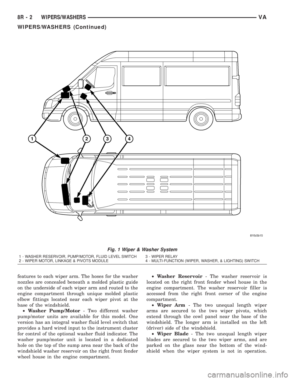
An electrically operated intermittent wiper and
washer system is standard factory-installed safety
equipment on this model (Fig. 1). The wiper and
washer system includes the following major compo-
nents, which are described in further detail else-
where in this service information:
²Check Valve- The washer system check valve
is integral to the plumbing fitting located in the
washer plumbing between the cowl plenum washer
hose and the two washer nozzle hoses, and is located
beneath the cowl top panel at the base of the wind-
shield in the engine compartment.
²Multi-Function Switch- The multi-function
switch is secured to the top of the steering column,just below the steering wheel. Only the left (lighting),
right (wiper) control stalks and the hazard warning
switch button for the multi-function switch are visi-
ble, the remainder of the switch is concealed beneath
the steering column shrouds. The multi-function
switch contains all of the switches for both the wiper
and washer systems.(Refer to 8 - ELECTRICAL/
LAMPS/LIGHTING - EXTERIOR/MULTI-FUNC-
TION SWITCH - DESCRIPTION)
²Washer Fluid Level Switch- The optional
washer fluid level switch is integral to a unique ver-
sion of the washer pump/motor unit, which is located
in a dedicated hole on the top of the sump area near
the back of the windshield washer reservoir on the
right front fender wheel house in the engine com-
partment.
²Washer Nozzle- A single washer nozzle with
three separate orifices is secured with integral snap
VAWIPERS/WASHERS 8R - 1
Page 284 of 1232
features to each wiper arm. The hoses for the washer
nozzles are concealed beneath a molded plastic guide
on the underside of each wiper arm and routed to the
engine compartment through unique molded plastic
elbow fittings located near each wiper pivot at the
base of the windshield.
²Washer Pump/Motor- Two different washer
pump/motor units are available for this model. One
version has an integral washer fluid level switch that
provides a hard wired input to the instrument cluster
for control of the optional washer fluid indicator. The
washer pump/motor unit is located in a dedicated
hole on the top of the sump area near the back of the
windshield washer reservoir on the right front fender
wheel house in the engine compartment.²Washer Reservoir- The washer reservoir is
located on the right front fender wheel house in the
engine compartment. The washer reservoir filler is
accessed from the right front corner of the engine
compartment.
²Wiper Arm- The two unequal length wiper
arms are secured to the two wiper pivots, which
extend through the cowl panel near the base of the
windshield. The longer arm is installed on the left
(driver) side of the windshield.
²Wiper Blade- The two unequal length wiper
blades are secured to the two wiper arms, and are
parked on the glass near the bottom of the wind-
shield when the wiper system is not in operation.
Fig. 1 Wiper & Washer System
1 - WASHER RESERVOIR, PUMP/MOTOR, FLUID LEVEL SWITCH 3 - WIPER RELAY
2 - WIPER MOTOR, LINKAGE & PIVOTS MODULE 4 - MULTI-FUNCTION (WIPER, WASHER, & LIGHTING) SWITCH
8R - 2 WIPERS/WASHERSVA
WIPERS/WASHERS (Continued)
Page 285 of 1232
The longer blade is installed on the left (driver) side
of the windshield.
²Wiper Linkage- The wiper pivots are the only
visible components of the wiper linkage. The remain-
der of the linkage is concealed within the engine
compartment just behind the hood opening. The
wiper linkage module includes the two wiper drive
links, the wiper motor crank arm, the two wiper piv-
ots, and the linkage and motor mounting bracket.
²Wiper Motor- The wiper motor is secured to
the wiper linkage module bracket on the underside of
the cowl panel within the engine compartment. The
wiper motor output shaft and crank arm extend
through a clearance hole in the mounting bracket,
where they are connected to a crank arm that drives
the wiper linkage.
²Wiper Relay- The wiper relay is located in a
dedicated receptacle on the lower left surface of the
fuse block underneath the steering column behind
the fuse access panel and the steering column open-
ing panel.
²Wiper, Turn Signals, Engine Start Control
Module- The wiper, turn signals and engine start
control module is integral to the fuse block located
underneath the steering column. The fuse block is
concealed behind the fuse access panel and the steer-
ing column opening panel, where it is secured with
screws to the steering column. The wiper, turn sig-
nals and engine start control module contains the
intermittent wipe logic circuitry, which includes
active electronic elements that allow it to provide the
intermittent wipe delay and the wipe-after-wash fea-
tures of the intermittent wipe system based upon
numerous hard wired inputs, then provides the
proper programmed hard wired control output to
operate the wiper motor through the wiper relay.
Hard wired circuitry connects the wiper and
washer system components to the electrical system of
the vehicle. These hard wired circuits are integral to
several wire harnesses, which are routed throughout
the vehicle and retained by many different methods.
These circuits may be connected to each other, to the
vehicle electrical system and to the wiper and washer
system components through the use of a combination
of soldered splices, splice block connectors, and many
different types of wire harness terminal connectors
and insulators. Refer to the appropriate wiring infor-
mation. The wiring information includes wiring dia-
grams, proper wire and connector repair procedures,
further details on wire harness routing and reten-
tion, as well as pin-out and location views for the
various wire harness connectors, splices and grounds.OPERATING MODES
The components of the wiper and washer system
are designed to provide the following operating
modes:
²Continuous Wipe Mode- The two-speed wiper
motor, the internal circuitry of the multi-function
switch, and the wiper relay work in concert to pro-
vide two continuous wipe cycles, low speed or high
speed.
²Intermittent Wipe Mode- The internal cir-
cuitry of the multi-function switch, the intermittent
wipe circuitry of the wiper, turn signals and engine
start control module in the fuse block, and the wiper
relay work in concert to provide an intermittent wipe
mode with a single, fixed delay interval.
²Pulse Wipe Mode- The internal circuitry of
the multi-function switch and the wiper relay work
in concert to provide a pulse wipe mode that will
allow the wiper motor to be operated for a single,
complete wipe cycle.
²Washer Mode- When the washer system is
activated with the multi-function switch while the
wiper system is operating, washer fluid will be dis-
pensed onto the windshield glass through the washer
nozzles for as long as the washer pump/motor is
energized.
²Wipe-After-Wash Mode- The intermittent
wipe circuitry of the wiper, turn signals and engine
start control module in the fuse block, and the wiper
relay provide a wipe-after-wash feature. If the wipers
are turned Off, this feature will operate the washer
pump/motor and the wipers for as long as the washer
system is activated, then provide several additional
wipe cycles after the washer system is deactivated
before parking the wiper blades near the base of the
windshield.
OPERATION
The wiper and washer system is designed to pro-
vide the vehicle operator with a convenient, safe, and
reliable means of maintaining visibility through the
windshield glass. The various components of this sys-
tem are designed to convert electrical energy pro-
duced by the vehicle electrical system into the
mechanical action of the wiper blades to wipe the
outside surface of the glass, as well as into the
hydraulic action of the washer system to apply
washer fluid stored in an on-board reservoir to the
area of the glass to be wiped. When combined, these
components provide the means to effectively main-
tain clear visibility for the vehicle operator by remov-
ing excess accumulations of rain, snow, bugs, mud, or
other minor debris from the outside windshield glass
surface that might be encountered while driving the
vehicle under numerous types of inclement operating
conditions.
VAWIPERS/WASHERS 8R - 3
WIPERS/WASHERS (Continued)
Page 286 of 1232
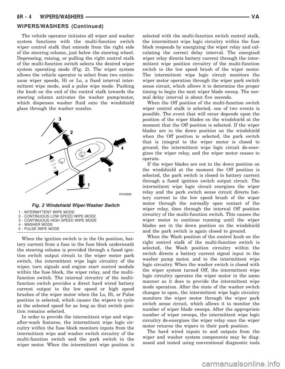
The vehicle operator initiates all wiper and washer
system functions with the multi-function switch
wiper control stalk that extends from the right side
of the steering column, just below the steering wheel.
Depressing, raising, or pulling the right control stalk
of the multi-function switch selects the desired wiper
system operating mode (Fig. 2). The wiper system
allows the vehicle operator to select from two contin-
uous wiper speeds, Hi or Lo, a fixed interval inter-
mittent wipe mode, and a pulse wipe mode. Pushing
the knob on the end of the control stalk towards the
steering column activates the washer pump/motor,
which dispenses washer fluid onto the windshield
glass through the washer nozzles.
When the ignition switch is in the On position, bat-
tery current from a fuse in the fuse block underneath
the steering column is provided through a fused igni-
tion switch output circuit to the wiper motor park
switch, the intermittent wipe logic circuitry of the
wiper, turn signals and engine start control module
within the fuse block, the wiper relay, and the multi-
function switch. The internal circuitry of the multi-
function switch provides a direct hard wired battery
current output to the low speed or high speed
brushes of the wiper motor when the Lo, Hi, or Pulse
position is selected, which causes the wipers to cycle
at the selected speed for as long as that switch posi-
tion remains selected.
In order to provide the intermittent wipe and wipe-
after-wash features, the intermittent wipe logic cir-
cuitry within the fuse block monitors inputs from the
intermittent wipe and washer switch circuitry of the
multi-function switch and the park switch in the
wiper motor. When the intermittent wipe position isselected with the multi-function switch control stalk,
the intermittent wipe logic circuitry within the fuse
block responds by energizing the wiper relay and cal-
culating the correct delay interval. The energized
wiper relay directs battery current through the inter-
mittent wipe position circuitry of the multi-function
switch to the low speed brush of the wiper motor.
The intermittent wipe logic circuit monitors the
wiper motor operation through the wiper park switch
sense circuit, which allows it to determine the proper
timing to begin the next wiper blade sweep. The nor-
mal delay interval is about five seconds.
When the Off position of the multi-function switch
wiper control stalk is selected, one of two events is
possible. The event that will occur depends upon the
position of the wiper blades on the windshield at the
moment that the Off position is selected. If the wiper
blades are in the down position on the windshield
when the Off position is selected, the park switch
that is integral to the wiper motor is closed to
ground, the intermittent wipe logic circuit de-ener-
gizes the wiper relay, and the wiper motor ceases to
operate.
If the wiper blades are not in the down position on
the windshield at the moment the Off position is
selected, the park switch is closed to battery current
through a fused ignition switch output circuit. The
intermittent wipe logic circuit energizes the wiper
relay and the park switch sense circuit directs bat-
tery current to the low speed brush of the wiper
motor through the normally open contact of the
wiper relay, then through the internal Off position
circuitry of the multi-function switch. This causes the
wiper motor to continue running until the wiper
blades are in the down position on the windshield
and the park switch is again closed to ground.
When the Wash position of the control knob on the
right control stalk of the multi-function switch is
selected, the Wash position circuitry within the
switch directs a battery current signal input to the
washer pump motor, and to the intermittent wipe
logic circuitry. When the washer switch is closed with
the wiper system turned Off, the intermittent wipe
logic circuitry operates the wiper motor in the same
manner as it does to provide the intermittent wipe
mode operation. After the state of the washer switch
changes to open, the intermittent wipe logic circuitry
monitors the wiper motor through the wiper park
switch sense circuit, which allows it to monitor the
number of wiper blade sweeps. After the appropriate
number of wiper sweeps, the intermittent wipe logic
circuitry de-energizes the wiper relay once the wiper
motor returns the wipers to their park position.
The hard wired inputs to and outputs from the
wiper and washer system components may be diag-
nosed and tested using conventional diagnostic tools
Fig. 2 Windshield Wiper/Washer Switch
1 - INTERMITTENT WIPE MODE
2 - CONTINUOUS LOW SPEED WIPE MODE
3 - CONTINUOUS HIGH SPEED WIPE MODE
4 - WASHER MODE
5 - PULSE WIPE MODE
8R - 4 WIPERS/WASHERSVA
WIPERS/WASHERS (Continued)
Page 301 of 1232
WASHERS/FRONT WIPER MOTOR -
INSTALLATION).
(2) Carefully position the wiper linkage module
and wiper motor to the underside of the cowl top
panel as a unit (Fig. 22).
(3) Install and tighten the two screws that secure
the wiper linkage module motor bracket to the flange
on the underside of the cowl top panel. Tighten the
screws to 6 N´m (50 in. lbs.).
(4) Install and tighten the nut and washer that
secures each wiper pivot housing to the outside of the
cowl top panel.
(5) Reconnect the wiper motor pigtail wire connec-
tor to the vehicle wire harness connector.
(6) Reinstall the ventilation housing onto the dash
panel and the underside of the cowl top panel (Fig.
21).
(7) Reinstall the wiper arms onto the wiper pivots.
(Refer to 8 - ELECTRICAL/WIPERS/WASHERS/
WIPER ARM - INSTALLATION).
(8) Reconnect the battery negative cable.
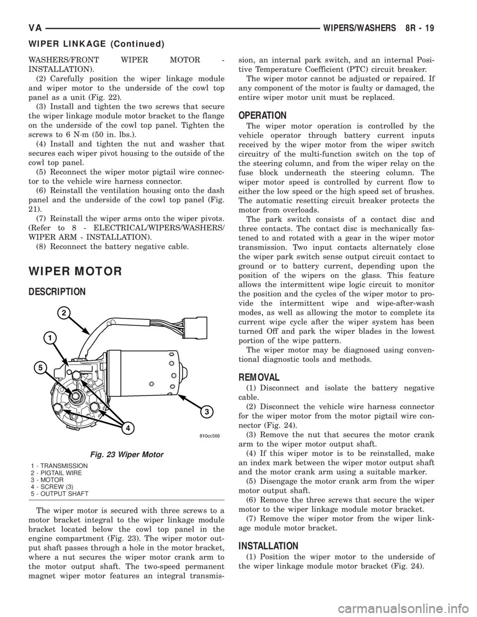
WIPER MOTOR
DESCRIPTION
The wiper motor is secured with three screws to a
motor bracket integral to the wiper linkage module
bracket located below the cowl top panel in the
engine compartment (Fig. 23). The wiper motor out-
put shaft passes through a hole in the motor bracket,
where a nut secures the wiper motor crank arm to
the motor output shaft. The two-speed permanent
magnet wiper motor features an integral transmis-sion, an internal park switch, and an internal Posi-
tive Temperature Coefficient (PTC) circuit breaker.
The wiper motor cannot be adjusted or repaired. If
any component of the motor is faulty or damaged, the
entire wiper motor unit must be replaced.
OPERATION
The wiper motor operation is controlled by the
vehicle operator through battery current inputs
received by the wiper motor from the wiper switch
circuitry of the multi-function switch on the top of
the steering column, and from the wiper relay on the
fuse block underneath the steering column. The
wiper motor speed is controlled by current flow to
either the low speed or the high speed set of brushes.
The automatic resetting circuit breaker protects the
motor from overloads.
The park switch consists of a contact disc and
three contacts. The contact disc is mechanically fas-
tened to and rotated with a gear in the wiper motor
transmission. Two input contacts alternately close
the wiper park switch sense output circuit contact to
ground or to battery current, depending upon the
position of the wipers on the glass. This feature
allows the intermittent wipe logic circuit to monitor
the position and the cycles of the wiper motor to pro-
vide the intermittent wipe and wipe-after-wash
modes, as well as allowing the motor to complete its
current wipe cycle after the wiper system has been
turned Off and park the wiper blades in the lowest
portion of the wipe pattern.
The wiper motor may be diagnosed using conven-
tional diagnostic tools and methods.
REMOVAL
(1) Disconnect and isolate the battery negative
cable.
(2) Disconnect the vehicle wire harness connector
for the wiper motor from the motor pigtail wire con-
nector (Fig. 24).
(3) Remove the nut that secures the motor crank
arm to the wiper motor output shaft.
(4) If this wiper motor is to be reinstalled, make
an index mark between the wiper motor output shaft
and the motor crank arm using a suitable marker.
(5) Disengage the motor crank arm from the wiper
motor output shaft.
(6) Remove the three screws that secure the wiper
motor to the wiper linkage module motor bracket.
(7) Remove the wiper motor from the wiper link-
age module motor bracket.
INSTALLATION
(1) Position the wiper motor to the underside of
the wiper linkage module motor bracket (Fig. 24).
Fig. 23 Wiper Motor
1 - TRANSMISSION
2 - PIGTAIL WIRE
3 - MOTOR
4 - SCREW (3)
5 - OUTPUT SHAFT
VAWIPERS/WASHERS 8R - 19
WIPER LINKAGE (Continued)
Page 302 of 1232
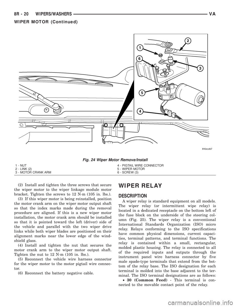
(2) Install and tighten the three screws that secure
the wiper motor to the wiper linkage module motor
bracket. Tighten the screws to 12 N´m (105 in. lbs.).
(3) If this wiper motor is being reinstalled, position
the motor crank arm on the wiper motor output shaft
so that the index marks made during the removal
procedure are aligned. If this is a new wiper motor
installation, the motor crank arm should be installed
so that it is pointed toward the left (driver) side of
the vehicle and parallel with the two wiper drive
links while both wiper blades are positioned on their
alignment marks near the lower edge of the wind-
shield glass.
(4) Install and tighten the nut that secures the
motor crank arm to the wiper motor output shaft.
Tighten the nut to 12 N´m (105 in. lbs.).
(5) Reconnect the vehicle wire harness connector
for the wiper motor to the motor pigtail wire connec-
tor.
(6) Reconnect the battery negative cable.WIPER RELAY
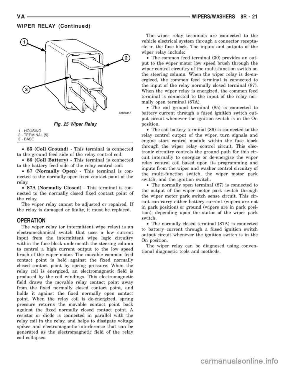
DESCRIPTION
A wiper relay is standard equipment on all models.
The wiper relay (or intermittent wipe relay) is
located in a dedicated receptacle on the bottom left of
the fuse block on the underside of the steering col-
umn (Fig. 25). The wiper relay is a conventional
International Standards Organization (ISO) micro
relay. Relays conforming to the ISO specifications
have common physical dimensions, current capaci-
ties, terminal patterns, and terminal functions. The
relay is contained within a small, rectangular,
molded plastic housing. The relay is connected to all
of the required inputs and outputs through the
instrument panel wire harness connector by five
male spade-type terminals that extend from the bot-
tom of the relay base. The ISO designation for each
terminal is molded into the base adjacent to the ter-
minal. The ISO terminal designations are as follows:
²30 (Common Feed)- This terminal is con-
nected to the movable contact point of the relay.
Fig. 24 Wiper Motor Remove/Install
1 - NUT 4 - PIGTAIL WIRE CONNECTOR
2 - LINK (2) 5 - WIPER MOTOR
3 - MOTOR CRANK ARM 6 - SCREW (3)
8R - 20 WIPERS/WASHERSVA
WIPER MOTOR (Continued)
Page 303 of 1232
²85 (Coil Ground)- This terminal is connected
to the ground feed side of the relay control coil.
²86 (Coil Battery)- This terminal is connected
to the battery feed side of the relay control coil.
²87 (Normally Open)- This terminal is con-
nected to the normally open fixed contact point of the
relay.
²87A (Normally Closed)- This terminal is con-
nected to the normally closed fixed contact point of
the relay.
The wiper relay cannot be adjusted or repaired. If
the relay is damaged or faulty, it must be replaced.
OPERATION
The wiper relay (or intermittent wipe relay) is an
electromechanical switch that uses a low current
input from the intermittent wipe logic circuitry
within the fuse block underneath the steering column
to control a high current output to the low speed
brush of the wiper motor. The movable common feed
contact point is held against the fixed normally
closed contact point by spring pressure. When the
relay coil is energized, an electromagnetic field is
produced by the coil windings. This electromagnetic
field draws the movable relay contact point away
from the fixed normally closed contact point, and
holds it against the fixed normally open contact
point. When the relay coil is de-energized, spring
pressure returns the movable contact point back
against the fixed normally closed contact point. A
resistor or diode is connected in parallel with the
relay coil in the relay, and helps to dissipate voltage
spikes and electromagnetic interference that can be
generated as the electromagnetic field of the relay
coil collapses.The wiper relay terminals are connected to the
vehicle electrical system through a connector recepta-
cle in the fuse block. The inputs and outputs of the
wiper relay include:
²The common feed terminal (30) provides an out-
put to the wiper motor low speed brush through the
wiper control circuitry of the multi-function switch on
the steering column. When the wiper relay is de-en-
ergized, the common feed terminal is connected to
the input of the relay normally closed terminal (87).
When the wiper relay is energized, the common feed
terminal is connected to the input of the relay nor-
mally open terminal (87A).
²The coil ground terminal (85) is connected to
battery current through a fused ignition switch out-
put circuit whenever the ignition switch is in the On
position.
²The coil battery terminal (86) is connected to the
relay control output of the wiper, turn signals and
engine start control module within the fuse block
through the wiper relay control circuit. This elec-
tronic circuitry controls the ground path for this cir-
cuit internally to energize or de-energize the wiper
relay control coil based upon its programming and
inputs from the wiper and washer control circuitry of
the multi-function switch, the wiper motor park
switch, and the ignition switch.
²The normally open terminal (87) is connected to
the output of the wiper motor park switch through
the wiper motor park switch sense circuit. This cir-
cuit can carry either battery current (wipers are not
in park position) or ground (wipers are in park posi-
tion), depending upon the status of the wiper park
switch.
²The normally closed terminal (87A) is connected
to battery current through a fused ignition switch
output circuit whenever the ignition switch is in the
On position.
The wiper relay can be diagnosed using conven-
tional diagnostic tools and methods.
Fig. 25 Wiper Relay
1 - HOUSING
2 - TERMINAL (5)
3 - BASE
VAWIPERS/WASHERS 8R - 21
WIPER RELAY (Continued)