2005 MERCEDES-BENZ SPRINTER brake
[x] Cancel search: brakePage 72 of 1232
BRAKE LINES
STANDARD PROCEDURE
STANDARD PROCEDURE - ISO FLARING
A preformed metal brake tube is recommended and
preferred for all repairs. However, double-wall steel
tube can be used for emergency repair when factory
replacement parts are not readily available.
To make a ISO flare use an ISO flaring tool kit.
(1) Cut off damaged tube with Tubing Cutter.
(2) Remove any burrs from the inside of the tube.
(3) Install tube nut on the tube.
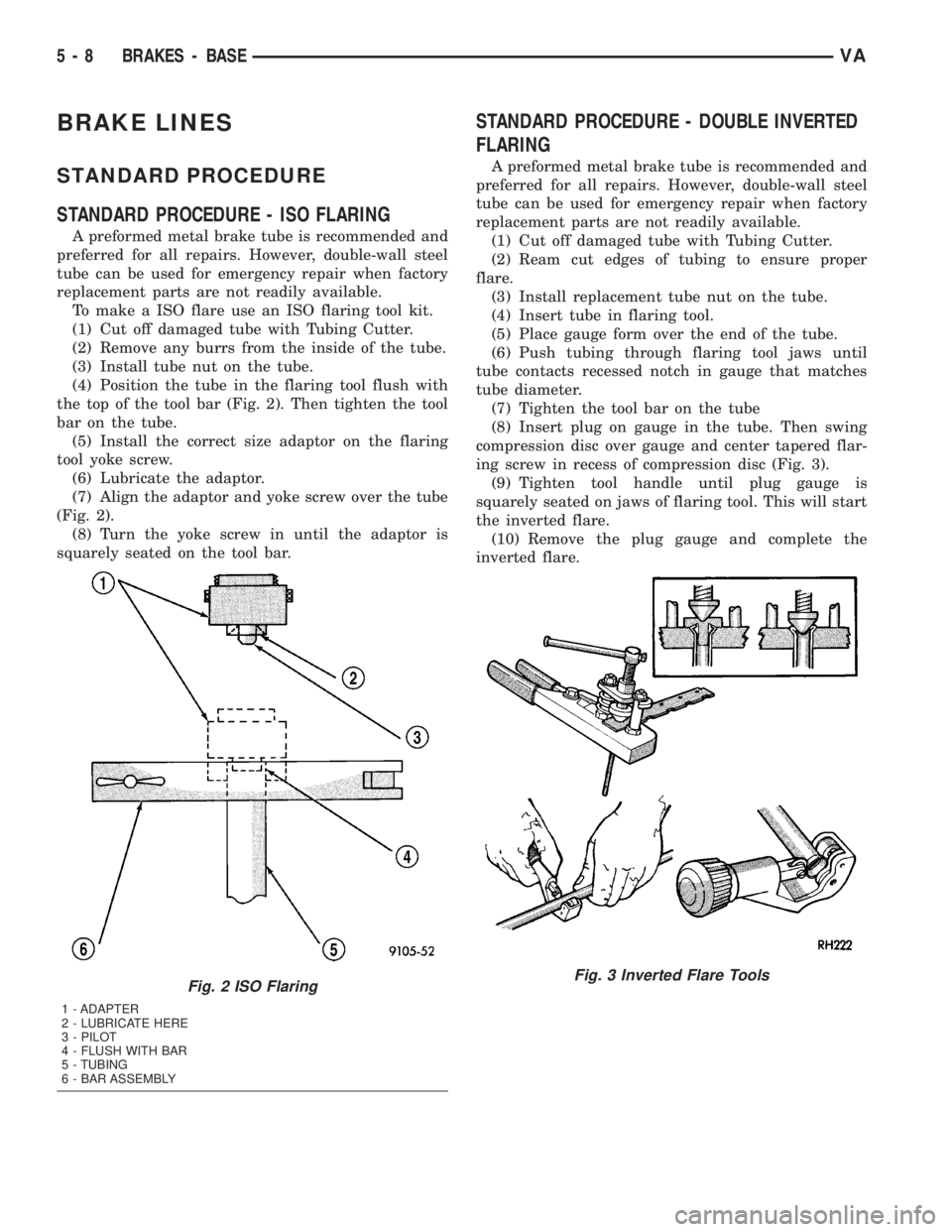
(4) Position the tube in the flaring tool flush with
the top of the tool bar (Fig. 2). Then tighten the tool
bar on the tube.
(5) Install the correct size adaptor on the flaring
tool yoke screw.
(6) Lubricate the adaptor.
(7) Align the adaptor and yoke screw over the tube
(Fig. 2).
(8) Turn the yoke screw in until the adaptor is
squarely seated on the tool bar.
STANDARD PROCEDURE - DOUBLE INVERTED
FLARING
A preformed metal brake tube is recommended and
preferred for all repairs. However, double-wall steel
tube can be used for emergency repair when factory
replacement parts are not readily available.
(1) Cut off damaged tube with Tubing Cutter.
(2) Ream cut edges of tubing to ensure proper
flare.
(3) Install replacement tube nut on the tube.
(4) Insert tube in flaring tool.
(5) Place gauge form over the end of the tube.
(6) Push tubing through flaring tool jaws until
tube contacts recessed notch in gauge that matches
tube diameter.
(7) Tighten the tool bar on the tube
(8) Insert plug on gauge in the tube. Then swing
compression disc over gauge and center tapered flar-
ing screw in recess of compression disc (Fig. 3).
(9) Tighten tool handle until plug gauge is
squarely seated on jaws of flaring tool. This will start
the inverted flare.
(10) Remove the plug gauge and complete the
inverted flare.
Fig. 2 ISO Flaring
1 - ADAPTER
2 - LUBRICATE HERE
3 - PILOT
4 - FLUSH WITH BAR
5 - TUBING
6 - BAR ASSEMBLY
Fig. 3 Inverted Flare Tools
5 - 8 BRAKES - BASEVA
Page 73 of 1232
BRAKE PADS/SHOES
REMOVAL
REMOVAL - FRONT (SRW)
(1) Unscrew the cap from the brake fluid reservoir.
(2) Raise and support the vehicle.
(3) Remove the front wheels (Refer to 22 - TIRES/
WHEELS/WHEELS - REMOVAL).
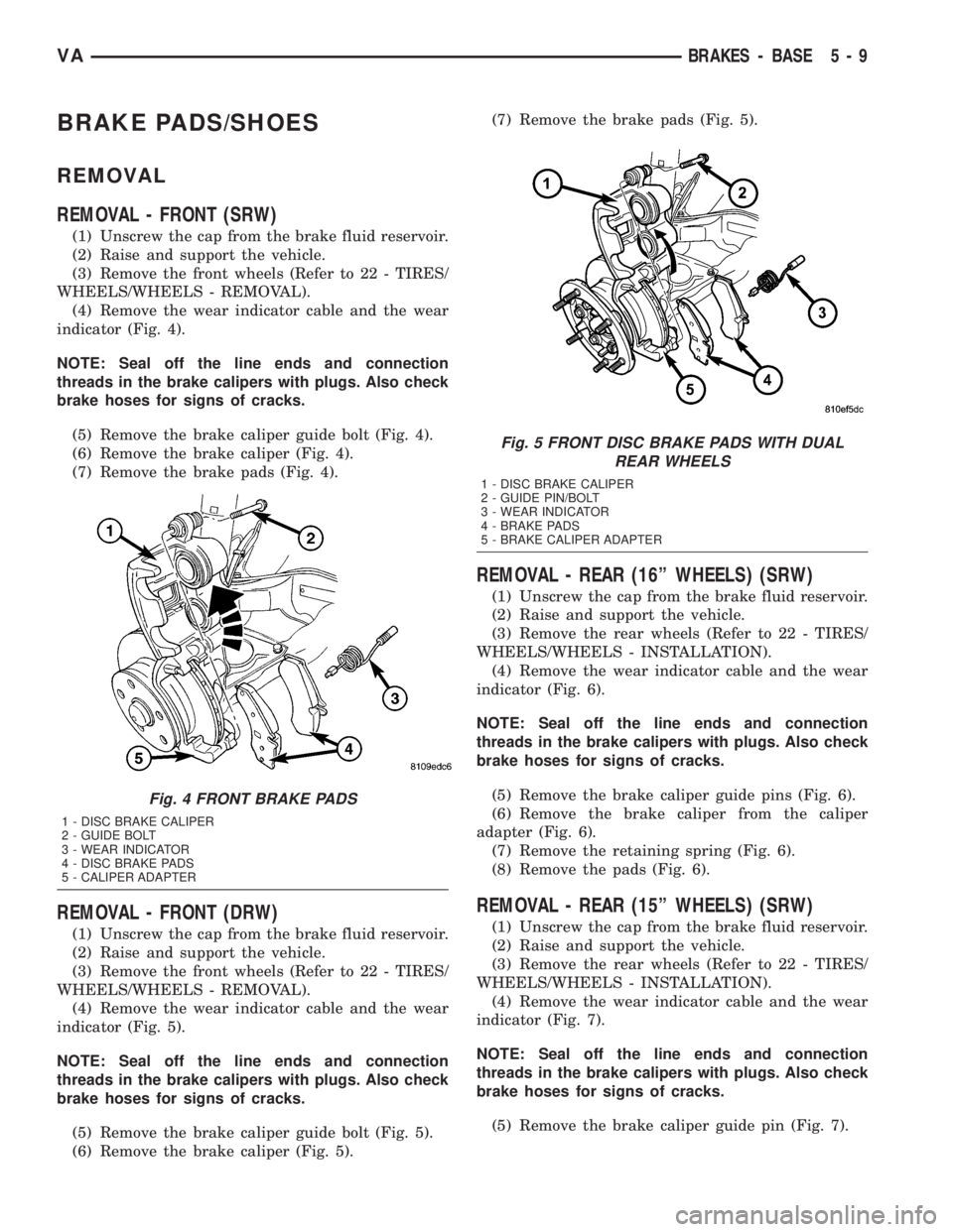
(4) Remove the wear indicator cable and the wear
indicator (Fig. 4).
NOTE: Seal off the line ends and connection
threads in the brake calipers with plugs. Also check
brake hoses for signs of cracks.
(5) Remove the brake caliper guide bolt (Fig. 4).
(6) Remove the brake caliper (Fig. 4).
(7) Remove the brake pads (Fig. 4).
REMOVAL - FRONT (DRW)
(1) Unscrew the cap from the brake fluid reservoir.
(2) Raise and support the vehicle.
(3) Remove the front wheels (Refer to 22 - TIRES/
WHEELS/WHEELS - REMOVAL).
(4) Remove the wear indicator cable and the wear
indicator (Fig. 5).
NOTE: Seal off the line ends and connection
threads in the brake calipers with plugs. Also check
brake hoses for signs of cracks.
(5) Remove the brake caliper guide bolt (Fig. 5).
(6) Remove the brake caliper (Fig. 5).(7) Remove the brake pads (Fig. 5).
REMOVAL - REAR (16º WHEELS) (SRW)
(1) Unscrew the cap from the brake fluid reservoir.
(2) Raise and support the vehicle.
(3) Remove the rear wheels (Refer to 22 - TIRES/
WHEELS/WHEELS - INSTALLATION).
(4) Remove the wear indicator cable and the wear
indicator (Fig. 6).
NOTE: Seal off the line ends and connection
threads in the brake calipers with plugs. Also check
brake hoses for signs of cracks.
(5) Remove the brake caliper guide pins (Fig. 6).
(6) Remove the brake caliper from the caliper
adapter (Fig. 6).
(7) Remove the retaining spring (Fig. 6).
(8) Remove the pads (Fig. 6).
REMOVAL - REAR (15º WHEELS) (SRW)
(1) Unscrew the cap from the brake fluid reservoir.
(2) Raise and support the vehicle.
(3) Remove the rear wheels (Refer to 22 - TIRES/
WHEELS/WHEELS - INSTALLATION).
(4) Remove the wear indicator cable and the wear
indicator (Fig. 7).
NOTE: Seal off the line ends and connection
threads in the brake calipers with plugs. Also check
brake hoses for signs of cracks.
(5) Remove the brake caliper guide pin (Fig. 7).
Fig. 4 FRONT BRAKE PADS
1 - DISC BRAKE CALIPER
2 - GUIDE BOLT
3 - WEAR INDICATOR
4 - DISC BRAKE PADS
5 - CALIPER ADAPTER
Fig. 5 FRONT DISC BRAKE PADS WITH DUAL
REAR WHEELS
1 - DISC BRAKE CALIPER
2 - GUIDE PIN/BOLT
3 - WEAR INDICATOR
4 - BRAKE PADS
5 - BRAKE CALIPER ADAPTER
VABRAKES - BASE 5 - 9
Page 74 of 1232
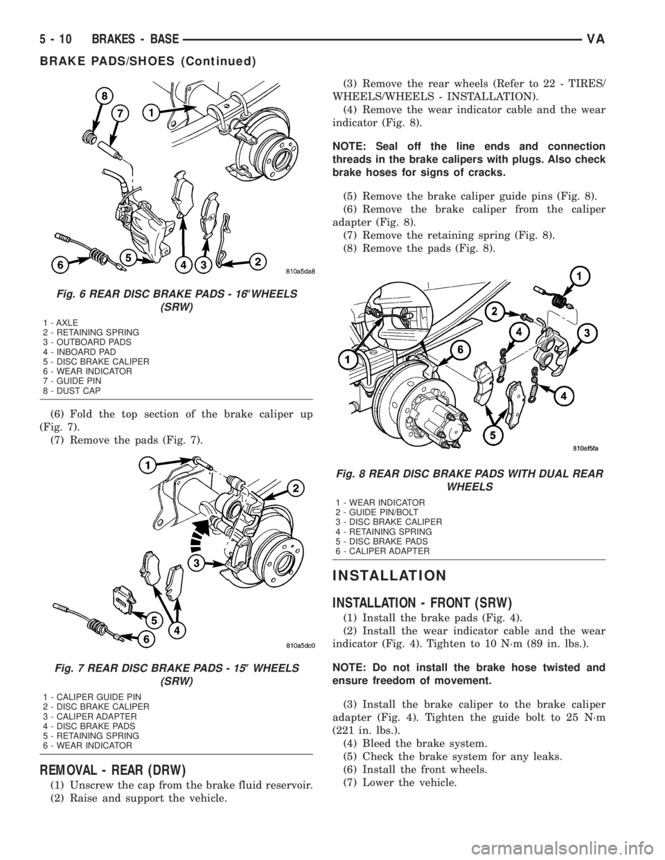
(6) Fold the top section of the brake caliper up
(Fig. 7).
(7) Remove the pads (Fig. 7).
REMOVAL - REAR (DRW)
(1) Unscrew the cap from the brake fluid reservoir.
(2) Raise and support the vehicle.(3) Remove the rear wheels (Refer to 22 - TIRES/
WHEELS/WHEELS - INSTALLATION).
(4) Remove the wear indicator cable and the wear
indicator (Fig. 8).
NOTE: Seal off the line ends and connection
threads in the brake calipers with plugs. Also check
brake hoses for signs of cracks.
(5) Remove the brake caliper guide pins (Fig. 8).
(6) Remove the brake caliper from the caliper
adapter (Fig. 8).
(7) Remove the retaining spring (Fig. 8).
(8) Remove the pads (Fig. 8).
INSTALLATION
INSTALLATION - FRONT (SRW)
(1) Install the brake pads (Fig. 4).
(2) Install the wear indicator cable and the wear
indicator (Fig. 4). Tighten to 10 N´m (89 in. lbs.).
NOTE: Do not install the brake hose twisted and
ensure freedom of movement.
(3) Install the brake caliper to the brake caliper
adapter (Fig. 4). Tighten the guide bolt to 25 N´m
(221 in. lbs.).
(4) Bleed the brake system.
(5) Check the brake system for any leaks.
(6) Install the front wheels.
(7) Lower the vehicle.
Fig. 6 REAR DISC BRAKE PADS - 16(WHEELS
(SRW)
1 - AXLE
2 - RETAINING SPRING
3 - OUTBOARD PADS
4 - INBOARD PAD
5 - DISC BRAKE CALIPER
6 - WEAR INDICATOR
7 - GUIDE PIN
8 - DUST CAP
Fig. 7 REAR DISC BRAKE PADS - 15(WHEELS
(SRW)
1 - CALIPER GUIDE PIN
2 - DISC BRAKE CALIPER
3 - CALIPER ADAPTER
4 - DISC BRAKE PADS
5 - RETAINING SPRING
6 - WEAR INDICATOR
Fig. 8 REAR DISC BRAKE PADS WITH DUAL REAR
WHEELS
1 - WEAR INDICATOR
2 - GUIDE PIN/BOLT
3 - DISC BRAKE CALIPER
4 - RETAINING SPRING
5 - DISC BRAKE PADS
6 - CALIPER ADAPTER
5 - 10 BRAKES - BASEVA
BRAKE PADS/SHOES (Continued)
Page 75 of 1232
INSTALLATION - FRONT (DRW)
(1) Install the brake pads (Fig. 5).
(2) Install the wear indicator cable and the wear
indicator (Fig. 5). Tighten to 10 N´m (89 in. lbs.).
NOTE: Do not install the brake hose twisted and
ensure freedom of movement.
(3) Install the brake caliper to the brake caliper
adapter (Fig. 5). Tighten the guide bolt to 25 N´m
(221 in. lbs.)(M8 bolt) or Tighten the guide bolt to 30
N´m (265 in. lbs.)(M10 10.9 bolt).
(4) Bleed the brake system.
(5) Check the brake system for any leaks.
(6) Install the front wheels.
(7) Lower the vehicle.
INSTALLATION - REAR (16º WHEELS) (SRW)
(1) Install the brake pads (Fig. 6).
(2) Install the wear indicator cable and the wear
indicator (Fig. 6). Tighten to 10 N´m (89 in. lbs.).
NOTE: Do not install the brake hose twisted and
ensure freedom of movement.
(3) Install the brake caliper to brake caliper
adapter (Fig. 6). Tighten the guide pins to 25 N´m
(221 in. lbs.) for M8 bolt or 30 N´m (266 in. lbs.) for
M10 bolt.
(4) Install the retaining spring (Fig. 6).
(5) Install the rear wheels (Refer to 22 - TIRES/
WHEELS/WHEELS - INSTALLATION).
(6) Lower the vehicle.
INSTALLATION - REAR (16º WHEELS) (SRW)
(1) Install the brake pads (Fig. 7).
(2) Install the wear indicator cable and the wear
indicator (Fig. 7). Tighten to 10 N´m (89 in. lbs.).
NOTE: Do not install the brake hose twisted and
ensure freedom of movement.
(3) Install the brake caliper to brake caliper
adapter (Fig. 7). Tighten the guide pin to 30 N´m
(266 in. lbs.) for M10 bolt.
(4) Install the rear wheels (Refer to 22 - TIRES/
WHEELS/WHEELS - INSTALLATION).
(5) Lower the vehicle.
INSTALLATION - REAR (DRW)
(1) Install the brake pads (Fig. 8).
(2) Install the wear indicator cable and the wear
indicator (Fig. 8). Tighten to 10 N´m (89 in. lbs.).
NOTE: Do not install the brake hose twisted and
ensure freedom of movement.(3) Install the brake caliper to brake caliper
adapter (Fig. 8). Tighten the guide pins to 25 N´m
(221 in. lbs.) for M8 bolt or 30 N´m (266 in. lbs.) for
M10 10.9 bolt.
(4) Install the retaining spring (Fig. 8).
(5) Install the rear wheels (Refer to 22 - TIRES/
WHEELS/WHEELS - INSTALLATION).
(6) Lower the vehicle.
DISC BRAKE CALIPERS
REMOVAL
REMOVAL - FRONT (SRW)
(1) Unscrew the cap from the brake fluid reservoir.
(2) Raise and support the vehicle.
(3) Remove the front wheels (Refer to 22 - TIRES/
WHEELS/WHEELS - REMOVAL).
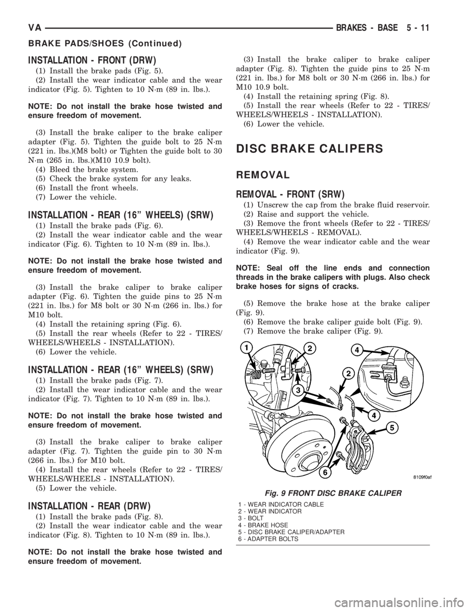
(4) Remove the wear indicator cable and the wear
indicator (Fig. 9).
NOTE: Seal off the line ends and connection
threads in the brake calipers with plugs. Also check
brake hoses for signs of cracks.
(5) Remove the brake hose at the brake caliper
(Fig. 9).
(6) Remove the brake caliper guide bolt (Fig. 9).
(7) Remove the brake caliper (Fig. 9).
Fig. 9 FRONT DISC BRAKE CALIPER
1 - WEAR INDICATOR CABLE
2 - WEAR INDICATOR
3 - BOLT
4 - BRAKE HOSE
5 - DISC BRAKE CALIPER/ADAPTER
6 - ADAPTER BOLTS
VABRAKES - BASE 5 - 11
BRAKE PADS/SHOES (Continued)
Page 76 of 1232
REMOVAL - FRONT (DRW)
(1) Unscrew the cap from the brake fluid reservoir.
(2) Raise and support the vehicle.
(3) Remove the front wheels (Refer to 22 - TIRES/
WHEELS/WHEELS - REMOVAL).
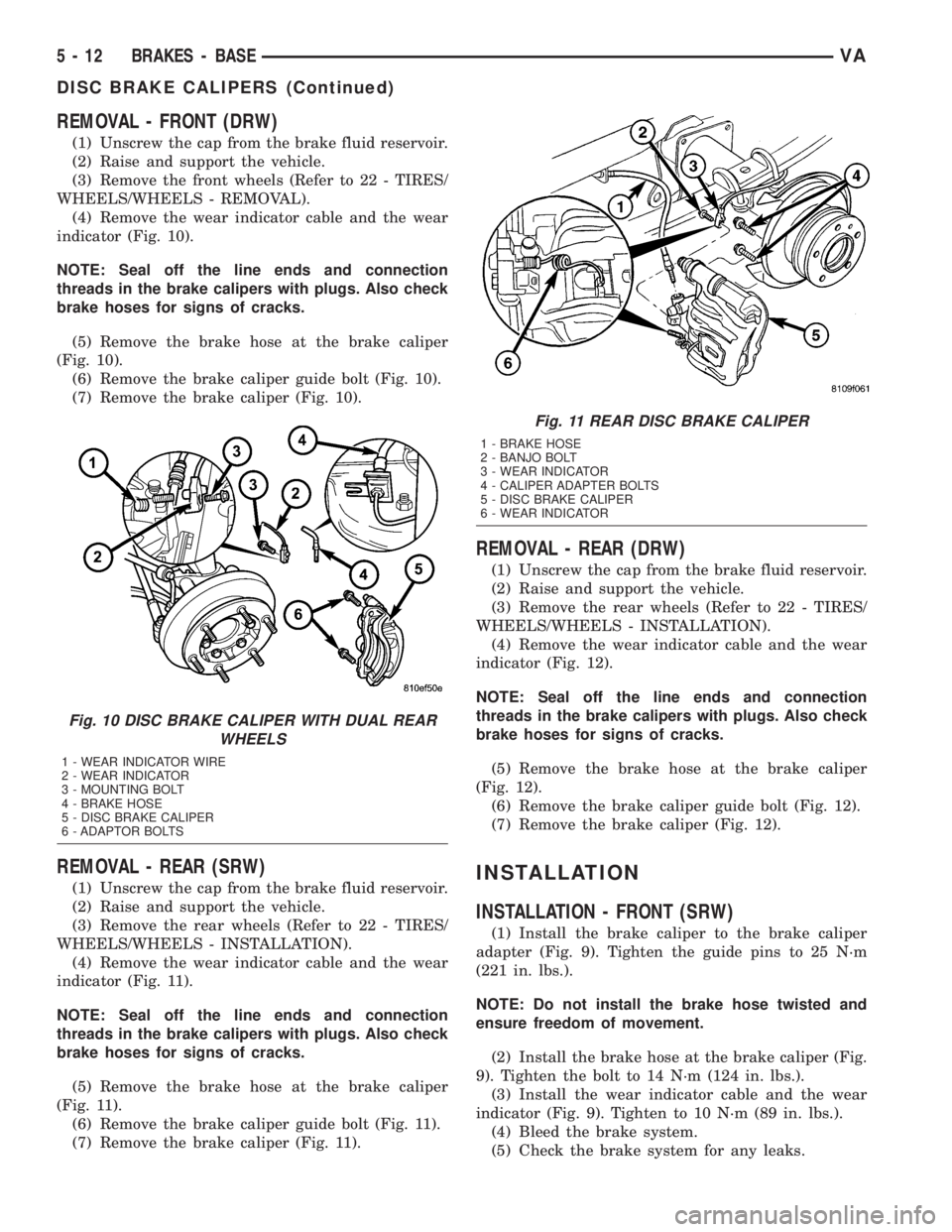
(4) Remove the wear indicator cable and the wear
indicator (Fig. 10).
NOTE: Seal off the line ends and connection
threads in the brake calipers with plugs. Also check
brake hoses for signs of cracks.
(5) Remove the brake hose at the brake caliper
(Fig. 10).
(6) Remove the brake caliper guide bolt (Fig. 10).
(7) Remove the brake caliper (Fig. 10).
REMOVAL - REAR (SRW)
(1) Unscrew the cap from the brake fluid reservoir.
(2) Raise and support the vehicle.
(3) Remove the rear wheels (Refer to 22 - TIRES/
WHEELS/WHEELS - INSTALLATION).
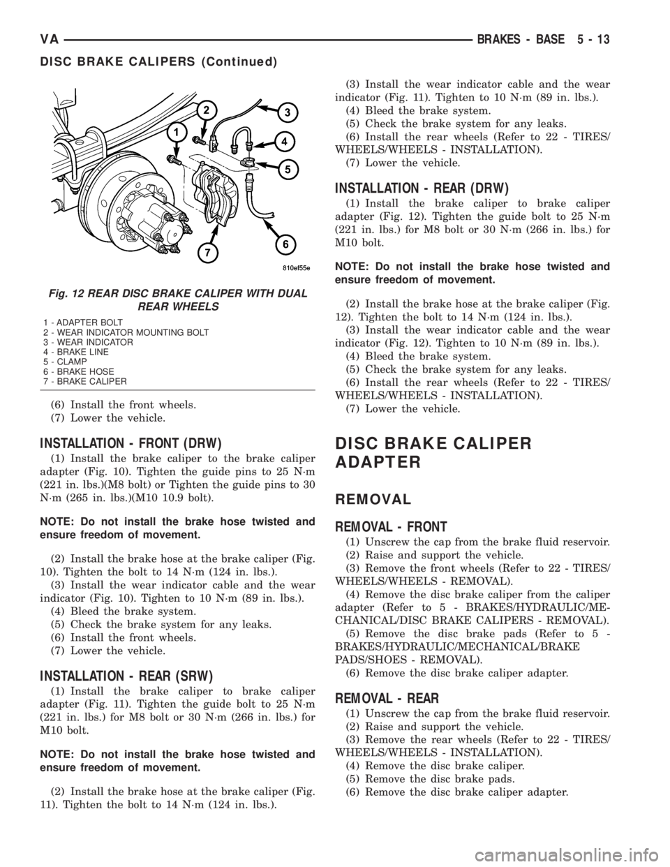
(4) Remove the wear indicator cable and the wear
indicator (Fig. 11).
NOTE: Seal off the line ends and connection
threads in the brake calipers with plugs. Also check
brake hoses for signs of cracks.
(5) Remove the brake hose at the brake caliper
(Fig. 11).
(6) Remove the brake caliper guide bolt (Fig. 11).
(7) Remove the brake caliper (Fig. 11).
REMOVAL - REAR (DRW)
(1) Unscrew the cap from the brake fluid reservoir.
(2) Raise and support the vehicle.
(3) Remove the rear wheels (Refer to 22 - TIRES/
WHEELS/WHEELS - INSTALLATION).
(4) Remove the wear indicator cable and the wear
indicator (Fig. 12).
NOTE: Seal off the line ends and connection
threads in the brake calipers with plugs. Also check
brake hoses for signs of cracks.
(5) Remove the brake hose at the brake caliper
(Fig. 12).
(6) Remove the brake caliper guide bolt (Fig. 12).
(7) Remove the brake caliper (Fig. 12).
INSTALLATION
INSTALLATION - FRONT (SRW)
(1) Install the brake caliper to the brake caliper
adapter (Fig. 9). Tighten the guide pins to 25 N´m
(221 in. lbs.).
NOTE: Do not install the brake hose twisted and
ensure freedom of movement.
(2) Install the brake hose at the brake caliper (Fig.
9). Tighten the bolt to 14 N´m (124 in. lbs.).
(3) Install the wear indicator cable and the wear
indicator (Fig. 9). Tighten to 10 N´m (89 in. lbs.).
(4) Bleed the brake system.
(5) Check the brake system for any leaks.
Fig. 10 DISC BRAKE CALIPER WITH DUAL REAR
WHEELS
1 - WEAR INDICATOR WIRE
2 - WEAR INDICATOR
3 - MOUNTING BOLT
4 - BRAKE HOSE
5 - DISC BRAKE CALIPER
6 - ADAPTOR BOLTS
Fig. 11 REAR DISC BRAKE CALIPER
1 - BRAKE HOSE
2 - BANJO BOLT
3 - WEAR INDICATOR
4 - CALIPER ADAPTER BOLTS
5 - DISC BRAKE CALIPER
6 - WEAR INDICATOR
5 - 12 BRAKES - BASEVA
DISC BRAKE CALIPERS (Continued)
Page 77 of 1232
(6) Install the front wheels.
(7) Lower the vehicle.
INSTALLATION - FRONT (DRW)
(1) Install the brake caliper to the brake caliper
adapter (Fig. 10). Tighten the guide pins to 25 N´m
(221 in. lbs.)(M8 bolt) or Tighten the guide pins to 30
N´m (265 in. lbs.)(M10 10.9 bolt).
NOTE: Do not install the brake hose twisted and
ensure freedom of movement.
(2) Install the brake hose at the brake caliper (Fig.
10). Tighten the bolt to 14 N´m (124 in. lbs.).
(3) Install the wear indicator cable and the wear
indicator (Fig. 10). Tighten to 10 N´m (89 in. lbs.).
(4) Bleed the brake system.
(5) Check the brake system for any leaks.
(6) Install the front wheels.
(7) Lower the vehicle.
INSTALLATION - REAR (SRW)
(1) Install the brake caliper to brake caliper
adapter (Fig. 11). Tighten the guide bolt to 25 N´m
(221 in. lbs.) for M8 bolt or 30 N´m (266 in. lbs.) for
M10 bolt.
NOTE: Do not install the brake hose twisted and
ensure freedom of movement.
(2) Install the brake hose at the brake caliper (Fig.
11). Tighten the bolt to 14 N´m (124 in. lbs.).(3) Install the wear indicator cable and the wear
indicator (Fig. 11). Tighten to 10 N´m (89 in. lbs.).
(4) Bleed the brake system.
(5) Check the brake system for any leaks.
(6) Install the rear wheels (Refer to 22 - TIRES/
WHEELS/WHEELS - INSTALLATION).
(7) Lower the vehicle.
INSTALLATION - REAR (DRW)
(1) Install the brake caliper to brake caliper
adapter (Fig. 12). Tighten the guide bolt to 25 N´m
(221 in. lbs.) for M8 bolt or 30 N´m (266 in. lbs.) for
M10 bolt.
NOTE: Do not install the brake hose twisted and
ensure freedom of movement.
(2) Install the brake hose at the brake caliper (Fig.
12). Tighten the bolt to 14 N´m (124 in. lbs.).
(3) Install the wear indicator cable and the wear
indicator (Fig. 12). Tighten to 10 N´m (89 in. lbs.).
(4) Bleed the brake system.
(5) Check the brake system for any leaks.
(6) Install the rear wheels (Refer to 22 - TIRES/
WHEELS/WHEELS - INSTALLATION).
(7) Lower the vehicle.
DISC BRAKE CALIPER
ADAPTER
REMOVAL
REMOVAL - FRONT
(1) Unscrew the cap from the brake fluid reservoir.
(2) Raise and support the vehicle.
(3) Remove the front wheels (Refer to 22 - TIRES/
WHEELS/WHEELS - REMOVAL).
(4) Remove the disc brake caliper from the caliper
adapter (Refer to 5 - BRAKES/HYDRAULIC/ME-
CHANICAL/DISC BRAKE CALIPERS - REMOVAL).
(5) Remove the disc brake pads (Refer to 5 -
BRAKES/HYDRAULIC/MECHANICAL/BRAKE
PADS/SHOES - REMOVAL).
(6) Remove the disc brake caliper adapter.
REMOVAL - REAR
(1) Unscrew the cap from the brake fluid reservoir.
(2) Raise and support the vehicle.
(3) Remove the rear wheels (Refer to 22 - TIRES/
WHEELS/WHEELS - INSTALLATION).
(4) Remove the disc brake caliper.
(5) Remove the disc brake pads.
(6) Remove the disc brake caliper adapter.
Fig. 12 REAR DISC BRAKE CALIPER WITH DUAL
REAR WHEELS
1 - ADAPTER BOLT
2 - WEAR INDICATOR MOUNTING BOLT
3 - WEAR INDICATOR
4 - BRAKE LINE
5 - CLAMP
6 - BRAKE HOSE
7 - BRAKE CALIPER
VABRAKES - BASE 5 - 13
DISC BRAKE CALIPERS (Continued)
Page 78 of 1232
INSTALLATION
INSTALLATION - FRONT
(1) Install the brake caliper adapter to the steering
knuckle. Tighten to 170 N´m (125 ft. lbs.).
(2) Install the disc brake shoes (Refer to 5 -
BRAKES/HYDRAULIC/MECHANICAL/BRAKE
PADS/SHOES - INSTALLATION).
NOTE: Do not install the brake hose twisted and
ensure freedom of movement.
(3) Install the disc brake caliper. Tighten the bolt
to 14 N´m (124 in. lbs.) (Refer to 5 - BRAKES/HY-
DRAULIC/MECHANICAL/DISC BRAKE CALIPERS
- INSTALLATION).
(4) Install the front wheels (Refer to 22 - TIRES/
WHEELS/WHEELS - INSTALLATION).
(5) Lower the vehicle.
INSTALLATION - REAR
(1) Install the brake caliper adapter to the axle
mount. Tighten to 90 N´m (66 ft. lbs.) for M12X1.5
bolt or 170 N´m (125 ft. lbs.) for M14X1.5 bolt.
(2) Install the disc brake pads (Refer to 5 -
BRAKES/HYDRAULIC/MECHANICAL/BRAKE
PADS/SHOES - INSTALLATION).
NOTE: Do not install the brake hose twisted and
ensure freedom of movement.
(3) Install the disc brake caliper (Refer to 5 -
BRAKES/HYDRAULIC/MECHANICAL/DISC
BRAKE CALIPERS - INSTALLATION).
(4) Install the rear wheels (Refer to 22 - TIRES/
WHEELS/WHEELS - INSTALLATION).
(5) Lower the vehicle.
FLUID
DIAGNOSIS AND TESTING - BRAKE FLUID
CONTAMINATION
Indications of fluid contamination are swollen or
deteriorated rubber parts.
Swollen rubber parts indicate the presence of
petroleum in the brake fluid.
To test for contamination, put a small amount of
drained brake fluid in clear glass jar. If fluid sepa-
rates into layers, there is mineral oil or other fluid
contamination of the brake fluid.
If brake fluid is contaminated, drain and thor-
oughly flush system. Replace master cylinder, ALB
Controller, caliper seals, Antilock Brakes hydraulic
unit and all hydraulic fluid hoses.
STANDARD PROCEDURE - BRAKE FLUID
LEVEL
Always clean the master cylinder reservoir and
caps before checking fluid level. If not cleaned, dirt
could enter the fluid.
The fluid fill level is indicated on the side of the
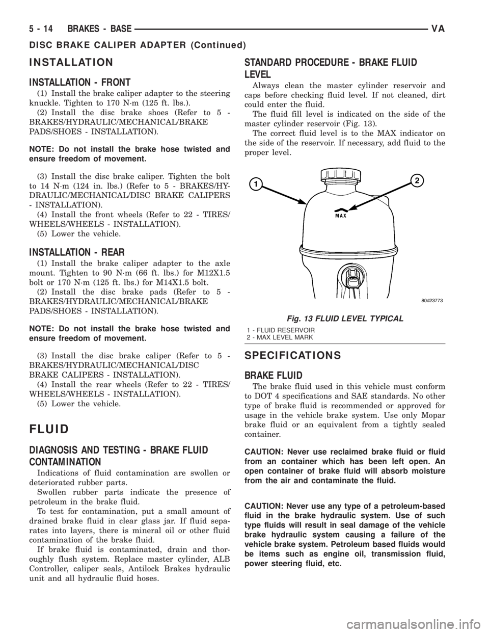
master cylinder reservoir (Fig. 13).
The correct fluid level is to the MAX indicator on
the side of the reservoir. If necessary, add fluid to the
proper level.
SPECIFICATIONS
BRAKE FLUID
The brake fluid used in this vehicle must conform
to DOT 4 specifications and SAE standards. No other
type of brake fluid is recommended or approved for
usage in the vehicle brake system. Use only Mopar
brake fluid or an equivalent from a tightly sealed
container.
CAUTION: Never use reclaimed brake fluid or fluid
from an container which has been left open. An
open container of brake fluid will absorb moisture
from the air and contaminate the fluid.
CAUTION: Never use any type of a petroleum-based
fluid in the brake hydraulic system. Use of such
type fluids will result in seal damage of the vehicle
brake hydraulic system causing a failure of the
vehicle brake system. Petroleum based fluids would
be items such as engine oil, transmission fluid,
power steering fluid, etc.
Fig. 13 FLUID LEVEL TYPICAL
1 - FLUID RESERVOIR
2 - MAX LEVEL MARK
5 - 14 BRAKES - BASEVA
DISC BRAKE CALIPER ADAPTER (Continued)
Page 79 of 1232
FLUID RESERVOIR
REMOVAL
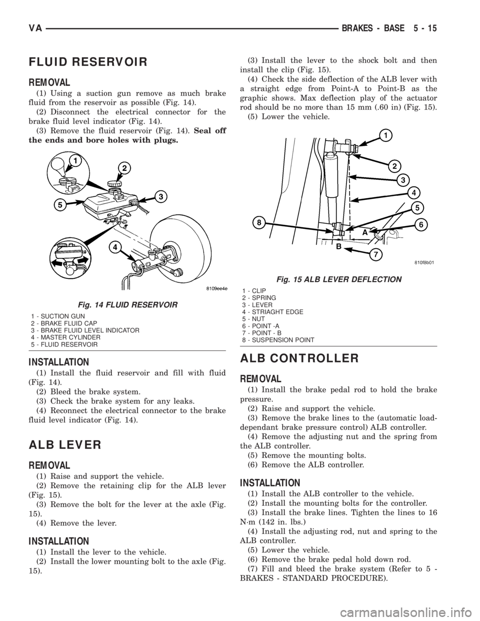
(1) Using a suction gun remove as much brake
fluid from the reservoir as possible (Fig. 14).
(2) Disconnect the electrical connector for the
brake fluid level indicator (Fig. 14).
(3) Remove the fluid reservoir (Fig. 14).Seal off
the ends and bore holes with plugs.
INSTALLATION
(1) Install the fluid reservoir and fill with fluid
(Fig. 14).
(2) Bleed the brake system.
(3) Check the brake system for any leaks.
(4) Reconnect the electrical connector to the brake
fluid level indicator (Fig. 14).
ALB LEVER
REMOVAL
(1) Raise and support the vehicle.
(2) Remove the retaining clip for the ALB lever
(Fig. 15).
(3) Remove the bolt for the lever at the axle (Fig.
15).
(4) Remove the lever.
INSTALLATION
(1) Install the lever to the vehicle.
(2) Install the lower mounting bolt to the axle (Fig.
15).(3) Install the lever to the shock bolt and then
install the clip (Fig. 15).
(4) Check the side deflection of the ALB lever with
a straight edge from Point-A to Point-B as the
graphic shows. Max deflection play of the actuator
rod should be no more than 15 mm (.60 in) (Fig. 15).
(5) Lower the vehicle.
ALB CONTROLLER
REMOVAL
(1) Install the brake pedal rod to hold the brake
pressure.
(2) Raise and support the vehicle.
(3) Remove the brake lines to the (automatic load-
dependant brake pressure control) ALB controller.
(4) Remove the adjusting nut and the spring from
the ALB controller.
(5) Remove the mounting bolts.
(6) Remove the ALB controller.
INSTALLATION
(1) Install the ALB controller to the vehicle.
(2) Install the mounting bolts for the controller.
(3) Install the brake lines. Tighten the lines to 16
N´m (142 in. lbs.)
(4) Install the adjusting rod, nut and spring to the
ALB controller.
(5) Lower the vehicle.
(6) Remove the brake pedal hold down rod.
(7) Fill and bleed the brake system (Refer to 5 -
BRAKES - STANDARD PROCEDURE).
Fig. 14 FLUID RESERVOIR
1 - SUCTION GUN
2 - BRAKE FLUID CAP
3 - BRAKE FLUID LEVEL INDICATOR
4 - MASTER CYLINDER
5 - FLUID RESERVOIR
Fig. 15 ALB LEVER DEFLECTION
1 - CLIP
2 - SPRING
3 - LEVER
4 - STRIAGHT EDGE
5 - NUT
6 - POINT -A
7 - POINT - B
8 - SUSPENSION POINT
VABRAKES - BASE 5 - 15