2005 MERCEDES-BENZ SPRINTER manual transmission
[x] Cancel search: manual transmissionPage 312 of 1232
²Grounds and ground connectors are identified
with a ªGº and follow the same series numbering as
the in-line connectors.
²Splices are identified with an ªSº and follow the
same series numbering as the in-line connectors.
²Component connectors are identified by the com-
ponent name instead of a number. Multiple connec-
tors on a component use a C1, C2, etc. identifier.
LOCATIONS
Section 8W-91 contains connector/ground/splice
location illustrations. The illustrations contain the
connector name (or number)/ground number/splice
number and component identification. Connector/
ground/splice location charts in section 8W-91 refer-
ence the figure numbers of the illustrations.
The abbreviation T/O is used in the component
location section to indicate a point in which the wir-
ing harness branches out to a component. The abbre-
viation N/S means Not Shown in the illustrations
WARNING
WARNINGS - GENERAL
WARNINGSprovide information to prevent per-
sonal injury and vehicle damage. Below is a list of
general warnings that should be followed any time a
vehicle is being serviced.
WARNING: ALWAYS WEAR SAFETY GLASSES FOR
EYE PROTECTION.
WARNING: USE SAFETY STANDS ANYTIME A PRO-
CEDURE REQUIRES BEING UNDER A VEHICLE.
WARNING: BE SURE THAT THE IGNITION SWITCH
ALWAYS IS IN THE OFF POSITION, UNLESS THE
PROCEDURE REQUIRES IT TO BE ON.
WARNING: SET THE PARKING BRAKE WHEN
WORKING ON ANY VEHICLE. AN AUTOMATIC
TRANSMISSION SHOULD BE IN PARK. A MANUAL
TRANSMISSION SHOULD BE IN NEUTRAL.
WARNING: OPERATE THE ENGINE ONLY IN A
WELL-VENTILATED AREA.
WARNING: KEEP AWAY FROM MOVING PARTS
WHEN THE ENGINE IS RUNNING, ESPECIALLY THE
FAN AND BELTS.WARNING: TO PREVENT SERIOUS BURNS, AVOID
CONTACT WITH HOT PARTS SUCH AS THE RADIA-
TOR, EXHAUST MANIFOLD(S), TAIL PIPE, CATA-
LYTIC CONVERTER AND MUFFLER.
WARNING: DO NOT ALLOW FLAME OR SPARKS
NEAR THE BATTERY. GASES ARE ALWAYS
PRESENT IN AND AROUND THE BATTERY.
WARNING: ALWAYS REMOVE RINGS, WATCHES,
LOOSE HANGING JEWELRY AND AVOID LOOSE
CLOTHING.
DIAGNOSIS AND TESTING - WIRING HARNESS
TROUBLESHOOTING TOOLS
When diagnosing a problem in an electrical circuit
there are several common tools necessary. These tools
are listed and explained below.
²Jumper Wire - This is a test wire used to con-
nect two points of a circuit. It can be used to bypass
an open in a circuit.
WARNING: NEVER USE A JUMPER WIRE ACROSS
A LOAD, SUCH AS A MOTOR, CONNECTED
BETWEEN A BATTERY FEED AND GROUND.
²Voltmeter - Used to check for voltage on a cir-
cuit. Always connect the black lead to a known good
ground and the red lead to the positive side of the
circuit.
CAUTION: Most of the electrical components used
in today's vehicles are Solid State. When checking
voltages in these circuits, use a meter with a 10 -
megohm or greater impedance rating.
²Ohmmeter - Used to check the resistance
between two points of a circuit. Low or no resistance
in a circuit means good continuity.
CAUTION: Most of the electrical components used
in today's vehicles are Solid State. When checking
resistance in these circuits use a meter with a 10 -
megohm or greater impedance rating. In addition,
make sure the power is disconnected from the cir-
cuit. Circuits that are powered up by the vehicle's
electrical system can cause damage to the equip-
ment and provide false readings.
8W - 01 - 6 8W-01 WIRING DIAGRAM INFORMATIONVA
WIRING DIAGRAM INFORMATION (Continued)
Page 791 of 1232
(3) Tighten the bolt of the transmission bell hous-
ing to oil pan to 40N´m (30 lbs. ft.).(4) Install the wiring harness duct (Fig. 51).
(5) Install the transmission lines (Fig. 51).
(6) Connect the oil level sensor (Fig. 51).
(7) Lower the vehicle.
(8) Lower the engine until the engine mount and
engine supports make contact.
(9) Start and hand tighten the engine mount bolts.
(10) Lower the engine the rest of the way and
remove the engine support fixture.
(11) Tighten the engine mount bolts to 83 N´m (61
lbs. ft.).
(12) Install the sway bar and tighten bolts to 30
N´m (22 lbs. ft.).
(13) Refill crankcase with the proper engine oil to
the proper level. Refer to owners manual for specifi-
cation.
(14) Reconnect negative battery cable.
WARNING: USE EXTREME CAUTION WHEN THE
ENGINE IS OPERATING. DO NOT PUT YOUR
HANDS NEAR THE PULLEYS, BELTS OR FAN. DO
NOT WEAR LOOSE CLOTHES.
(15) Start the engine and inspect for leaks.
OIL PUMP
REMOVAL
REMOVAL
(1) Remove the oil pan (Refer to 9 - ENGINE/LU-
BRICATION/OIL PAN - REMOVAL).
(2) Remove the oil pump bolts (Fig. 51).
(3) Press the chain tensioner off of the oil pump
chain, and remove pump from chain.
(4) Remove the oil pump, pick-up tube and O-ring
(Fig. 51).
REMOVAL- OIL PUMP CHAIN
(1) Disconnect negative battery cable.
(2) Remove oil pan (Refer to 9 - ENGINE/LUBRI-
CATION/OIL PAN - REMOVAL).
(3) Remove oil pump (Refer to 9 - ENGINE/LU-
BRICATION/OIL PUMP - REMOVAL).
NOTE: Make sure the pin of the thrust spindle is
backed out into the thrust spindle before seating
the thrust spindle to the oil pump chain.
(4) Using special tool #8948 and thrust pin #9311,
position and fit chain seperating tool and thrust spin-
dle onto a link of the oil pump chain (Fig. 54).
(5) Screw the thrust pin in and seperate the oil
pump chain link.
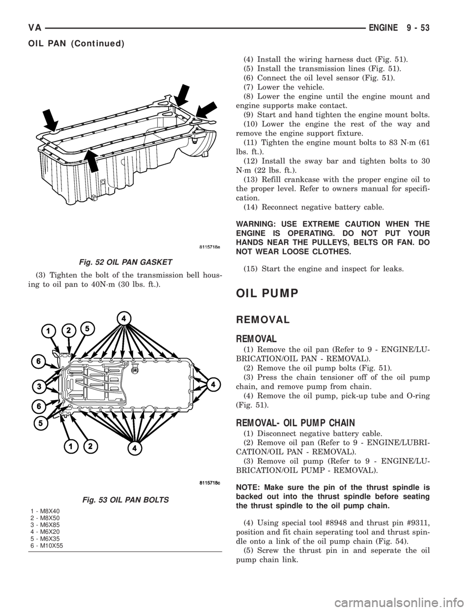
Fig. 52 OIL PAN GASKET
Fig. 53 OIL PAN BOLTS
1 - M8X40
2 - M8X50
3 - M6X85
4 - M6X20
5 - M6X35
6 - M10X55
VAENGINE 9 - 53
OIL PAN (Continued)
Page 1009 of 1232
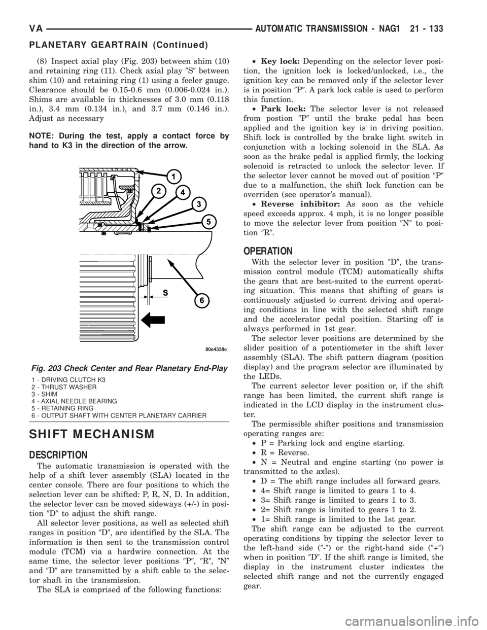
(8) Inspect axial play (Fig. 203) between shim (10)
and retaining ring (11). Check axial play9S9between
shim (10) and retaining ring (1) using a feeler gauge.
Clearance should be 0.15-0.6 mm (0.006-0.024 in.).
Shims are available in thicknesses of 3.0 mm (0.118
in.), 3.4 mm (0.134 in.), and 3.7 mm (0.146 in.).
Adjust as necessary
NOTE: During the test, apply a contact force by
hand to K3 in the direction of the arrow.
SHIFT MECHANISM
DESCRIPTION
The automatic transmission is operated with the
help of a shift lever assembly (SLA) located in the
center console. There are four positions to which the
selection lever can be shifted: P, R, N, D. In addition,
the selector lever can be moved sideways (+/-) in posi-
tion9D9to adjust the shift range.
All selector lever positions, as well as selected shift
ranges in position9D9, are identified by the SLA. The
information is then sent to the transmission control
module (TCM) via a hardwire connection. At the
same time, the selector lever positions9P9,9R9,9N9
and9D9are transmitted by a shift cable to the selec-
tor shaft in the transmission.
The SLA is comprised of the following functions:²Key lock:Depending on the selector lever posi-
tion, the ignition lock is locked/unlocked, i.e., the
ignition key can be removed only if the selector lever
is in position9P9. A park lock cable is used to perform
this function.
²Park lock:The selector lever is not released
from postion9P9until the brake pedal has been
applied and the ignition key is in driving position.
Shift lock is controlled by the brake light switch in
conjunction with a locking solenoid in the SLA. As
soon as the brake pedal is applied firmly, the locking
solenoid is retracted to unlock the selector lever. If
the selector lever cannot be moved out of position9P9
due to a malfunction, the shift lock function can be
overriden (see operator's manual).
²Reverse inhibitor:As soon as the vehicle
speed exceeds approx. 4 mph, it is no longer possible
to move the selector lever from position9N9to posi-
tion9R9.
OPERATION
With the selector lever in position9D9, the trans-
mission control module (TCM) automatically shifts
the gears that are best-suited to the current operat-
ing situation. This means that shifting of gears is
continuously adjusted to current driving and operat-
ing conditions in line with the selected shift range
and the accelerator pedal position. Starting off is
always performed in 1st gear.
The selector lever positions are determined by the
slider position of a potentiometer in the shift lever
assembly (SLA). The shift pattern diagram (position
display) and the program selector are illuminated by
the LEDs.
The current selector lever position or, if the shift
range has been limited, the current shift range is
indicated in the LCD display in the instrument clus-
ter.
The permissible shifter positions and transmission
operating ranges are:
²P = Parking lock and engine starting.
²R = Reverse.
²N = Neutral and engine starting (no power is
transmitted to the axles).
²D = The shift range includes all forward gears.
²4= Shift range is limited to gears 1 to 4.
²3= Shift range is limited to gears 1 to 3.
²2= Shift range is limited to gears 1 to 2.
²1= Shift range is limited to the 1st gear.
The shift range can be adjusted to the current
operating conditions by tipping the selector lever to
the left-hand side (9-9) or the right-hand side (9+9)
when in position9D9. If the shift range is limited, the
display in the instrument cluster indicates the
selected shift range and not the currently engaged
gear.
Fig. 203 Check Center and Rear Planetary End-Play
1 - DRIVING CLUTCH K3
2 - THRUST WASHER
3 - SHIM
4 - AXIAL NEEDLE BEARING
5 - RETAINING RING
6 - OUTPUT SHAFT WITH CENTER PLANETARY CARRIER
VAAUTOMATIC TRANSMISSION - NAG1 21 - 133
PLANETARY GEARTRAIN (Continued)
Page 1010 of 1232
Tipping the shift lever will have the following
results:
²Tipping the selector lever toward(-(one
time after another:The shift range is reduced in
descending sequence by one gear each time, i.e., from
D-4-3-2-1.Iftheselected limitation of the shift
range would result in a downshift causing excessive
engine speed, the shifting is not executed and the
engaged gear as well as the shift range remain
unchanged. This is to prevent the engine from over-
speeding. Engine retardation is low with the selector
lever in position9D9. To make use of the full braking
power of the engine,9manual9downshifting by tip-
ping the lever towards the left-hand side is recom-
mended. If this has been done, subsequent upshifting
must be carried out manually as well.
²Tipping the selector lever toward(-(and
holding it in this position:The currently engaged
gear in range9D9is indicated in the instrument clus-
ter display and the shift range is limited to this gear.
²Tipping the selector lever toward(+(one
time after another:The shift range is increased by
one gear each time and the increased shift range is
displayed in the instrument cluster; possibly, the
transmission upshifts to a faster gear.
²Tipping the selector lever toward(+(sev-
eral times:The shift range is increased by one gear
each time the lever is tipped until the shift range
ends up in9D9.
²Tipping the selector lever toward(+(and
holding it in this position:The shift range is
extended immediately to9D9, shift ranges are indi-
cated in ascending sequence; possibly, the transmis-
sion upshifts to a faster gear due to the extension of
the shift range.
REMOVAL
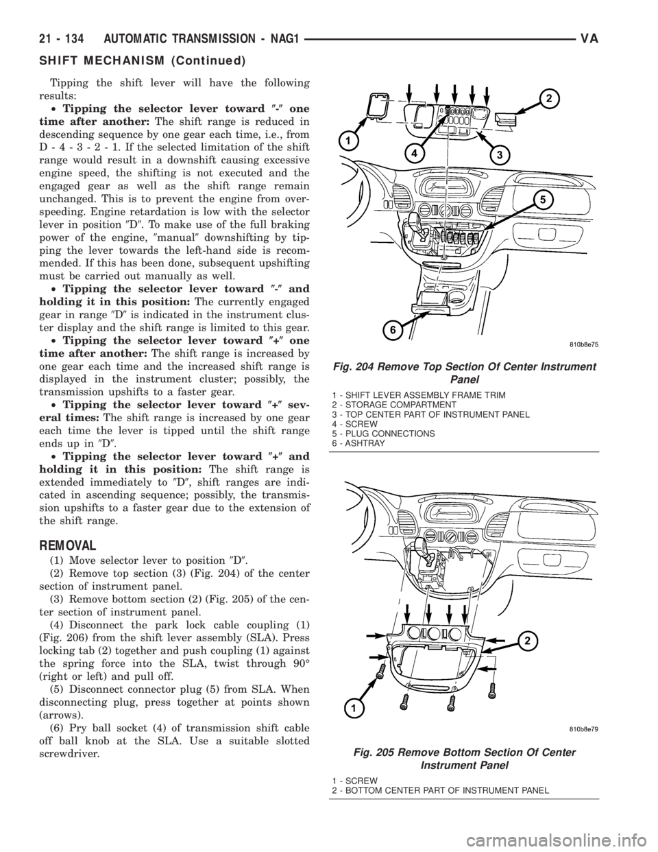
(1) Move selector lever to position9D9.
(2) Remove top section (3) (Fig. 204) of the center
section of instrument panel.
(3) Remove bottom section (2) (Fig. 205) of the cen-
ter section of instrument panel.
(4) Disconnect the park lock cable coupling (1)
(Fig. 206) from the shift lever assembly (SLA). Press
locking tab (2) together and push coupling (1) against
the spring force into the SLA, twist through 90É
(right or left) and pull off.
(5) Disconnect connector plug (5) from SLA. When
disconnecting plug, press together at points shown
(arrows).
(6) Pry ball socket (4) of transmission shift cable
off ball knob at the SLA. Use a suitable slotted
screwdriver.
Fig. 204 Remove Top Section Of Center Instrument
Panel
1 - SHIFT LEVER ASSEMBLY FRAME TRIM
2 - STORAGE COMPARTMENT
3 - TOP CENTER PART OF INSTRUMENT PANEL
4 - SCREW
5 - PLUG CONNECTIONS
6 - ASHTRAY
Fig. 205 Remove Bottom Section Of Center
Instrument Panel
1 - SCREW
2 - BOTTOM CENTER PART OF INSTRUMENT PANEL
21 - 134 AUTOMATIC TRANSMISSION - NAG1VA
SHIFT MECHANISM (Continued)
Page 1223 of 1232
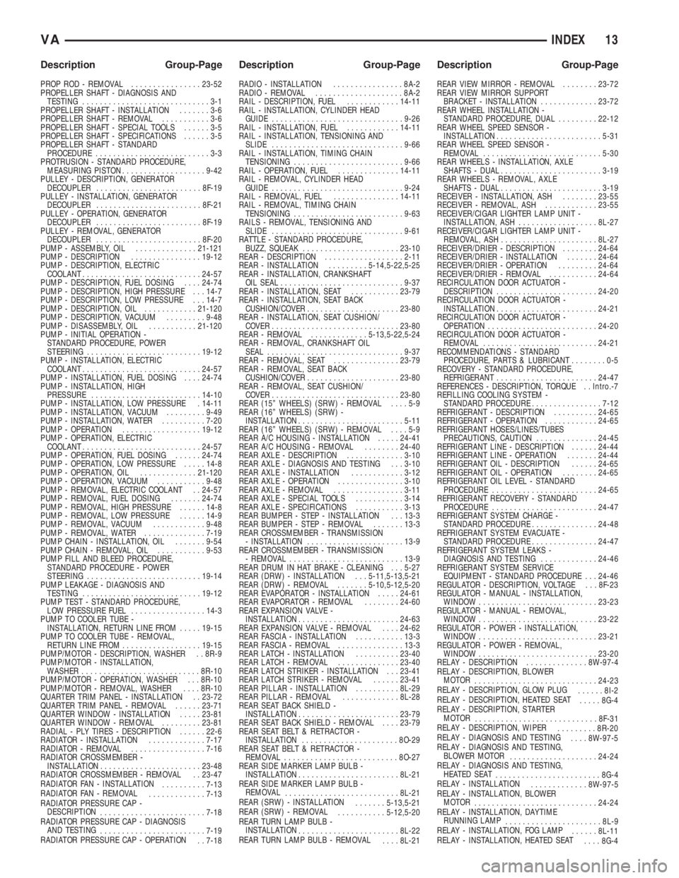
PROP ROD - REMOVAL................23-52
PROPELLER SHAFT - DIAGNOSIS AND
TESTING.............................3-1
PROPELLER SHAFT - INSTALLATION.......3-6
PROPELLER SHAFT - REMOVAL...........3-6
PROPELLER SHAFT - SPECIAL TOOLS......3-5
PROPELLER SHAFT - SPECIFICATIONS......3-5
PROPELLER SHAFT - STANDARD
PROCEDURE..........................3-3
PROTRUSION - STANDARD PROCEDURE,
MEASURING PISTON...................9-42
PULLEY - DESCRIPTION, GENERATOR
DECOUPLER........................8F-19
PULLEY - INSTALLATION, GENERATOR
DECOUPLER........................8F-21
PULLEY - OPERATION, GENERATOR
DECOUPLER........................8F-19
PULLEY - REMOVAL, GENERATOR
DECOUPLER........................8F-20
PUMP - ASSEMBLY, OIL..............21-121
PUMP - DESCRIPTION................19-12
PUMP - DESCRIPTION, ELECTRIC
COOLANT...........................24-57
PUMP - DESCRIPTION, FUEL DOSING....24-74
PUMP - DESCRIPTION, HIGH PRESSURE . . . 14-7
PUMP - DESCRIPTION, LOW PRESSURE . . . 14-7
PUMP - DESCRIPTION, OIL............21-120
PUMP - DESCRIPTION, VACUUM.........9-48
PUMP - DISASSEMBLY, OIL...........21-120
PUMP - INITIAL OPERATION -
STANDARD PROCEDURE, POWER
STEERING..........................19-12
PUMP - INSTALLATION, ELECTRIC
COOLANT...........................24-57
PUMP - INSTALLATION, FUEL DOSING....24-74
PUMP - INSTALLATION, HIGH
PRESSURE.........................14-10
PUMP - INSTALLATION, LOW PRESSURE . 14-11
PUMP - INSTALLATION, VACUUM.........9-49
PUMP - INSTALLATION, WATER..........7-20
PUMP - OPERATION..................19-12
PUMP - OPERATION, ELECTRIC
COOLANT...........................24-57
PUMP - OPERATION, FUEL DOSING......24-74
PUMP - OPERATION, LOW PRESSURE.....14-8
PUMP - OPERATION, OIL.............21-120
PUMP - OPERATION, VACUUM...........9-48
PUMP - REMOVAL, ELECTRIC COOLANT . . 24-57
PUMP - REMOVAL, FUEL DOSING.......24-74
PUMP - REMOVAL, HIGH PRESSURE......14-8
PUMP - REMOVAL, LOW PRESSURE......14-9
PUMP - REMOVAL, VACUUM............9-48
PUMP - REMOVAL, WATER..............7-19
PUMP CHAIN - INSTALLATION, OIL.......9-54
PUMP CHAIN - REMOVAL, OIL...........9-53
PUMP FILL AND BLEED PROCEDURE,
STANDARD PROCEDURE - POWER
STEERING..........................19-14
PUMP LEAKAGE - DIAGNOSIS AND
TESTING...........................19-12
PUMP TEST - STANDARD PROCEDURE,
LOW PRESSURE FUEL.................14-3
PUMP TO COOLER TUBE -
INSTALLATION, RETURN LINE FROM.....19-15
PUMP TO COOLER TUBE - REMOVAL,
RETURN LINE FROM..................19-15
PUMP/MOTOR - DESCRIPTION, WASHER . . 8R-9
PUMP/MOTOR - INSTALLATION,
WASHER...........................8R-10
PUMP/MOTOR - OPERATION, WASHER . . . 8R-10
PUMP/MOTOR - REMOVAL, WASHER....8R-10
QUARTER TRIM PANEL - INSTALLATION . . 23-72
QUARTER TRIM PANEL - REMOVAL......23-71
QUARTER WINDOW - INSTALLATION.....23-81
QUARTER WINDOW - REMOVAL.........23-81
RADIAL - PLY TIRES - DESCRIPTION......22-6
RADIATOR - INSTALLATION.............7-17
RADIATOR - REMOVAL.................7-16
RADIATOR CROSSMEMBER -
INSTALLATION.......................23-48
RADIATOR CROSSMEMBER - REMOVAL . . 23-47
RADIATOR FAN - INSTALLATION
..........7-13
RADIATOR FAN - REMOVAL
.............7-13
RADIATOR PRESSURE CAP -
DESCRIPTION
........................7-18
RADIATOR PRESSURE CAP - DIAGNOSIS
AND TESTING
........................7-19
RADIATOR PRESSURE CAP - OPERATION
. . 7-18RADIO - INSTALLATION................8A-2
RADIO - REMOVAL....................8A-2
RAIL - DESCRIPTION, FUEL............14-11
RAIL - INSTALLATION, CYLINDER HEAD
GUIDE..............................9-26
RAIL - INSTALLATION, FUEL............14-11
RAIL - INSTALLATION, TENSIONING AND
SLIDE..............................9-66
RAIL - INSTALLATION, TIMING CHAIN
TENSIONING.........................9-66
RAIL - OPERATION, FUEL..............14-11
RAIL - REMOVAL, CYLINDER HEAD
GUIDE..............................9-24
RAIL - REMOVAL, FUEL...............14-11
RAIL - REMOVAL, TIMING CHAIN
TENSIONING.........................9-63
RAILS - REMOVAL, TENSIONING AND
SLIDE..............................9-61
RATTLE - STANDARD PROCEDURE,
BUZZ, SQUEAK......................23-10
REAR - DESCRIPTION..................2-11
REAR - INSTALLATION.........5-14,5-22,5-25
REAR - INSTALLATION, CRANKSHAFT
OIL SEAL............................9-37
REAR - INSTALLATION, SEAT...........23-79
REAR - INSTALLATION, SEAT BACK
CUSHION/COVER.....................23-80
REAR - INSTALLATION, SEAT CUSHION/
COVER.............................23-80
REAR - REMOVAL.............5-13,5-22,5-24
REAR - REMOVAL, CRANKSHAFT OIL
SEAL...............................9-37
REAR - REMOVAL, SEAT...............23-79
REAR - REMOVAL, SEAT BACK
CUSHION/COVER.....................23-80
REAR - REMOVAL, SEAT CUSHION/
COVER.............................23-80
REAR (15º WHEELS) (SRW) - REMOVAL....5-9
REAR (16º WHEELS) (SRW) -
INSTALLATION........................5-11
REAR (16º WHEELS) (SRW) - REMOVAL....5-9
REAR A/C HOUSING - INSTALLATION.....24-41
REAR A/C HOUSING - REMOVAL........24-40
REAR AXLE - DESCRIPTION.............3-10
REAR AXLE - DIAGNOSIS AND TESTING . . . 3-10
REAR AXLE - INSTALLATION............3-12
REAR AXLE - OPERATION...............3-10
REAR AXLE - REMOVAL................3-11
REAR AXLE - SPECIAL TOOLS...........3-14
REAR AXLE - SPECIFICATIONS...........3-13
REAR BUMPER - STEP - INSTALLATION . . . 13-3
REAR BUMPER - STEP - REMOVAL.......13-3
REAR CROSSMEMBER - TRANSMISSION
- INSTALLATION......................13-9
REAR CROSSMEMBER - TRANSMISSION
- REMOVAL..........................13-9
REAR DRUM IN HAT BRAKE - CLEANING . . . 5-27
REAR (DRW) - INSTALLATION . . . 5-11,5-13,5-21
REAR (DRW) - REMOVAL.......5-10,5-12,5-20
REAR EVAPORATOR - INSTALLATION.....24-61
REAR EVAPORATOR - REMOVAL........24-60
REAR EXPANSION VALVE -
INSTALLATION.......................24-63
REAR EXPANSION VALVE - REMOVAL....24-62
REAR FASCIA - INSTALLATION...........13-3
REAR FASCIA - REMOVAL...............13-3
REAR LATCH - INSTALLATION..........23-40
REAR LATCH - REMOVAL..............23-40
REAR LATCH STRIKER - INSTALLATION . . . 23-41
REAR LATCH STRIKER - REMOVAL......23-41
REAR PILLAR - INSTALLATION..........8L-29
REAR PILLAR - REMOVAL.............8L-28
REAR SEAT BACK SHIELD -
INSTALLATION.......................23-79
REAR SEAT BACK SHIELD - REMOVAL....23-79
REAR SEAT BELT & RETRACTOR -
INSTALLATION......................8O-29
REAR SEAT BELT & RETRACTOR -
REMOVAL..........................8O-27
REAR SIDE MARKER LAMP BULB -
INSTALLATION.......................8L-21
REAR SIDE MARKER LAMP BULB -
REMOVAL
..........................8L-21
REAR (SRW) - INSTALLATION
.......5-13,5-21
REAR (SRW) - REMOVAL
...........5-12,5-20
REAR TURN LAMP BULB -
INSTALLATION
.......................8L-22
REAR TURN LAMP BULB - REMOVAL
....8L-21REAR VIEW MIRROR - REMOVAL........23-72
REAR VIEW MIRROR SUPPORT
BRACKET - INSTALLATION.............23-72
REAR WHEEL INSTALLATION -
STANDARD PROCEDURE, DUAL.........22-12
REAR WHEEL SPEED SENSOR -
INSTALLATION........................5-31
REAR WHEEL SPEED SENSOR -
REMOVAL...........................5-30
REAR WHEELS - INSTALLATION, AXLE
SHAFTS - DUAL.......................3-19
REAR WHEELS - REMOVAL, AXLE
SHAFTS - DUAL.......................3-19
RECEIVER - INSTALLATION, ASH........23-55
RECEIVER - REMOVAL, ASH............23-55
RECEIVER/CIGAR LIGHTER LAMP UNIT -
INSTALLATION, ASH..................8L-27
RECEIVER/CIGAR LIGHTER LAMP UNIT -
REMOVAL, ASH......................8L-27
RECEIVER/DRIER - DESCRIPTION........24-64
RECEIVER/DRIER - INSTALLATION.......24-64
RECEIVER/DRIER - OPERATION.........24-64
RECEIVER/DRIER - REMOVAL...........24-64
RECIRCULATION DOOR ACTUATOR -
DESCRIPTION.......................24-20
RECIRCULATION DOOR ACTUATOR -
INSTALLATION.......................24-21
RECIRCULATION DOOR ACTUATOR -
OPERATION.........................24-20
RECIRCULATION DOOR ACTUATOR -
REMOVAL..........................24-21
RECOMMENDATIONS - STANDARD
PROCEDURE, PARTS & LUBRICANT........0-5
RECOVERY - STANDARD PROCEDURE,
REFRIGERANT.......................24-47
REFERENCES - DESCRIPTION, TORQUE . . Intro.-7
REFILLING COOLING SYSTEM -
STANDARD PROCEDURE................7-12
REFRIGERANT - DESCRIPTION..........24-65
REFRIGERANT - OPERATION............24-65
REFRIGERANT HOSES/LINES/TUBES
PRECAUTIONS, CAUTION..............24-45
REFRIGERANT LINE - DESCRIPTION......24-44
REFRIGERANT LINE - OPERATION.......24-44
REFRIGERANT OIL - DESCRIPTION......24-65
REFRIGERANT OIL - OPERATION........24-65
REFRIGERANT OIL LEVEL - STANDARD
PROCEDURE........................24-65
REFRIGERANT RECOVERY - STANDARD
PROCEDURE........................24-47
REFRIGERANT SYSTEM CHARGE -
STANDARD PROCEDURE...............24-48
REFRIGERANT SYSTEM EVACUATE -
STANDARD PROCEDURE...............24-47
REFRIGERANT SYSTEM LEAKS -
DIAGNOSIS AND TESTING.............24-46
REFRIGERANT SYSTEM SERVICE
EQUIPMENT - STANDARD PROCEDURE . . . 24-46
REGULATOR - DESCRIPTION, VOLTAGE . . . 8F-23
REGULATOR - MANUAL - INSTALLATION,
WINDOW...........................23-23
REGULATOR - MANUAL - REMOVAL,
WINDOW...........................23-22
REGULATOR - POWER - INSTALLATION,
WINDOW...........................23-21
REGULATOR - POWER - REMOVAL,
WINDOW...........................23-20
RELAY - DESCRIPTION..............8W-97-4
RELAY - DESCRIPTION, BLOWER
MOTOR
............................24-23
RELAY - DESCRIPTION, GLOW PLUG
......8I-2
RELAY - DESCRIPTION, HEATED SEAT
.....8G-4
RELAY - DESCRIPTION, STARTER
MOTOR
............................8F-31
RELAY - DESCRIPTION, WIPER
.........8R-20
RELAY - DIAGNOSIS AND TESTING
....8W-97-5
RELAY - DIAGNOSIS AND TESTING,
BLOWER MOTOR
....................24-24
RELAY - DIAGNOSIS AND TESTING,
HEATED SEAT
........................8G-4
RELAY - INSTALLATION
.............8W-97-5
RELAY - INSTALLATION, BLOWER
MOTOR
............................24-24
RELAY - INSTALLATION, DAYTIME
RUNNING LAMP
......................8L-9
RELAY - INSTALLATION, FOG LAMP
......8L-11
RELAY - INSTALLATION, HEATED SEAT
....8G-4
VAINDEX 13
Description Group-Page Description Group-Page Description Group-Page