2005 MERCEDES-BENZ SPRINTER length
[x] Cancel search: lengthPage 290 of 1232
voir on the right front fender wheel house in the
engine compartment. Only a molded plastic nipple
with a clear vent tube are visible near the top of the
washer pump/motor unit that is equipped with the
optional fluid level switch when it is installed in the
reservoir. The vent tube is routed to and retained in
an integral clip located behind the reservoir filler cap
near the top of the reservoir. This version of the
washer pump/motor unit also has a third terminal
pin in its integral connector receptacle. The washer
fluid level switch cannot be adjusted or repaired. If
faulty or damaged, the entire washer pump/motor
unit must be replaced.
OPERATION
The washer fluid level switch monitors the level of
the washer fluid in the washer reservoir. When the
fluid level in the washer reservoir is at or above the
predetermined minimum, the switch contacts are
open. When the fluid level in the washer reservoir
falls below the predetermined minimum, the switch
contacts of the normally open switch close. The
washer fluid level switch is connected to the vehicle
electrical system through the washer pump/motor
unit take out and connector of the vehicle wire har-
ness. The switch receives a path to ground at all
times through another take out of the vehicle wire
harness with a single eyelet terminal connector that
is secured under a ground screw located near the
right headlamp in the engine compartment.The switch is connected in series between ground
and the washer fluid switch sense input to the Elec-
troMechanical Instrument Cluster (EMIC). When the
switch closes, the EMIC senses the ground on the
washer fluid switch sense circuit. The EMIC is pro-
grammed to respond to this input by illuminating the
washer fluid indicator. The washer fluid level switch
input to the EMIC may be diagnosed using conven-
tional diagnostic tools and methods.
WASHER HOSES/TUBES
DESCRIPTION
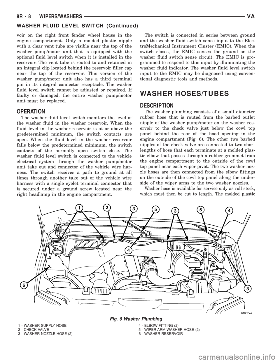
The washer plumbing consists of a small diameter
rubber hose that is routed from the barbed outlet
nipple of the washer pump/motor on the washer res-
ervoir to the check valve just below the cowl top
panel behind the rear of the hood opening in the
engine compartment (Fig. 6). The other two barbed
nipples of the check valve are connected to two short
lengths of hose that each terminate at a molded plas-
tic elbow that passes through a rubber grommet from
the engine compartment to the outside of the cowl
top panel near each wiper pivot. The two washer noz-
zle hoses are then connected from the elbow fittings
on the outside of the cowl top panel along the under-
side of the wiper arms to the two washer nozzles.
Washer hose is available for service only as roll stock,
which must then be cut to length. The molded plastic
Fig. 6 Washer Plumbing
1 - WASHER SUPPLY HOSE 4 - ELBOW FITTING (2)
2 - CHECK VALVE 5 - WIPER ARM WASHER HOSE (2)
3 - WASHER NOZZLE HOSE (2) 6 - WASHER RESERVOIR
8R - 8 WIPERS/WASHERSVA
WASHER FLUID LEVEL SWITCH (Continued)
Page 295 of 1232
WIPER ARM
DESCRIPTION
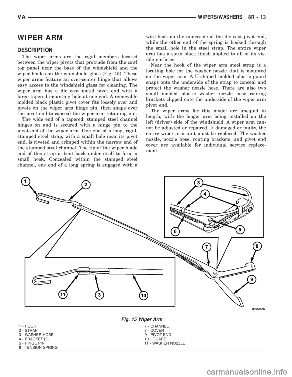
The wiper arms are the rigid members located
between the wiper pivots that protrude from the cowl
top panel near the base of the windshield and the
wiper blades on the windshield glass (Fig. 15). These
wiper arms feature an over-center hinge that allows
easy access to the windshield glass for cleaning. The
wiper arm has a die cast metal pivot end with a
large tapered mounting hole at one end. A removable
molded black plastic pivot cover fits loosely over and
pivots on the wiper arm hinge pin, then snaps over
the pivot end to conceal the wiper arm retaining nut.
The wide end of a tapered, stamped steel channel
hinges on and is secured with a hinge pin to the
pivot end of the wiper arm. One end of a long, rigid,
stamped steel strap, with a small hole near its pivot
end, is riveted and crimped within the narrow end of
the stamped steel channel. The tip of the wiper blade
end of this strap is bent back under itself to form a
small hook. Concealed within the stamped steel
channel, one end of a long spring is engaged with awire hook on the underside of the die cast pivot end,
while the other end of the spring is hooked through
the small hole in the steel strap. The entire wiper
arm has a satin black finish applied to all of its vis-
ible surfaces.
Near the hook of the wiper arm steel strap is a
locating hole for the washer nozzle that is mounted
on the wiper arm. A U-shaped molded plastic guard
snaps onto the underside of the strap to conceal and
protect the washer nozzle hose. There are also two
small molded plastic washer nozzle hose routing
brackets clipped onto the underside of the wiper arm
pivot end.
The wiper arms for this model are unequal in
length, with the longer arm being installed on the
left (driver) side of the windshield. A wiper arm can-
not be adjusted or repaired. If damaged or faulty, the
entire wiper arm unit must be replaced. The washer
nozzle, nozzle hose, routing brackets, and pivot end
cover are available for individual service replace-
ment.
Fig. 15 Wiper Arm
1 - HOOK 7 - CHANNEL
2 - STRAP 8 - COVER
3 - WASHER HOSE 9 - PIVOT END
4 - BRACKET (2) 10 - GUARD
5 - HINGE PIN 11 - WASHER NOZZLE
6 - TENSION SPRING
VAWIPERS/WASHERS 8R - 13
Page 296 of 1232
OPERATION
The wiper arms are designed to mechanically
transmit the motion from the wiper pivots to the
wiper blades. The wiper arm must be properly
indexed to the wiper pivot in order to maintain the
proper wiper blade travel on the glass. The tapered
mounting hole in the wiper arm pivot end interlocks
with the serrations on the outer circumference of the
wiper pivot shaft, allowing positive engagement and
finite adjustment of this connection. The mounting
nut locks the wiper arm to the threaded end of the
wiper pivot shaft. The spring-loaded wiper arm hinge
controls the down-force applied through the tip of the
wiper arm to the wiper blade on the glass. The hook
formation on the tip of the wiper arm provides a cra-
dle for securing and latching the wiper blade pivot
block to the wiper arm.
REMOVAL
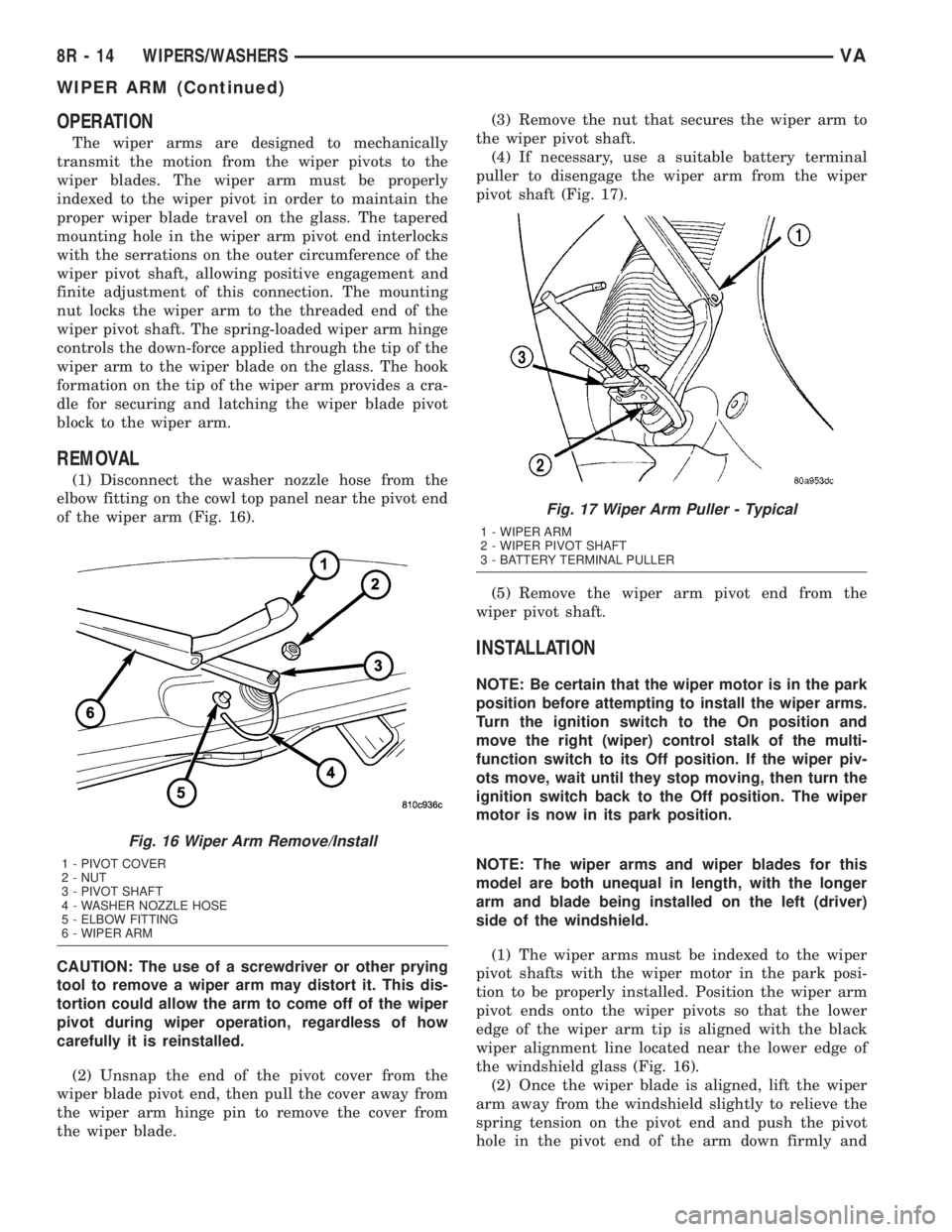
(1) Disconnect the washer nozzle hose from the
elbow fitting on the cowl top panel near the pivot end
of the wiper arm (Fig. 16).
CAUTION: The use of a screwdriver or other prying
tool to remove a wiper arm may distort it. This dis-
tortion could allow the arm to come off of the wiper
pivot during wiper operation, regardless of how
carefully it is reinstalled.
(2) Unsnap the end of the pivot cover from the
wiper blade pivot end, then pull the cover away from
the wiper arm hinge pin to remove the cover from
the wiper blade.(3) Remove the nut that secures the wiper arm to
the wiper pivot shaft.
(4) If necessary, use a suitable battery terminal
puller to disengage the wiper arm from the wiper
pivot shaft (Fig. 17).
(5) Remove the wiper arm pivot end from the
wiper pivot shaft.
INSTALLATION
NOTE: Be certain that the wiper motor is in the park
position before attempting to install the wiper arms.
Turn the ignition switch to the On position and
move the right (wiper) control stalk of the multi-
function switch to its Off position. If the wiper piv-
ots move, wait until they stop moving, then turn the
ignition switch back to the Off position. The wiper
motor is now in its park position.
NOTE: The wiper arms and wiper blades for this
model are both unequal in length, with the longer
arm and blade being installed on the left (driver)
side of the windshield.
(1) The wiper arms must be indexed to the wiper
pivot shafts with the wiper motor in the park posi-
tion to be properly installed. Position the wiper arm
pivot ends onto the wiper pivots so that the lower
edge of the wiper arm tip is aligned with the black
wiper alignment line located near the lower edge of
the windshield glass (Fig. 16).
(2) Once the wiper blade is aligned, lift the wiper
arm away from the windshield slightly to relieve the
spring tension on the pivot end and push the pivot
hole in the pivot end of the arm down firmly and
Fig. 16 Wiper Arm Remove/Install
1 - PIVOT COVER
2 - NUT
3 - PIVOT SHAFT
4 - WASHER NOZZLE HOSE
5 - ELBOW FITTING
6 - WIPER ARM
Fig. 17 Wiper Arm Puller - Typical
1 - WIPER ARM
2 - WIPER PIVOT SHAFT
3 - BATTERY TERMINAL PULLER
8R - 14 WIPERS/WASHERSVA
WIPER ARM (Continued)
Page 297 of 1232
evenly over the wiper pivot shaft. Gently lower the
wiper arm until the wiper blade rests on the glass.
(3) Install and tighten the nut that secures the
wiper arm to the wiper pivot shaft. Tighten the nut
to 24 N´m (18 ft. lbs.).
(4) Wet the windshield glass, then operate the wip-
ers. Move the right (wiper) control stalk of the multi-
function switch to the Off position, then check for the
correct wiper arm position and readjust as required.
(5) Engage the pivot cover with the wiper arm
hinge pin, then push the pivot end of the cover down
firmly and evenly until it snaps over the wiper blade
pivot end.
(6) Reconnect the washer nozzle hose to the elbow
fitting on the cowl top panel near the pivot end of the
wiper arm.
WIPER BLADE
DESCRIPTION
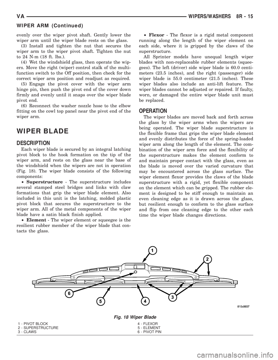
Each wiper blade is secured by an integral latching
pivot block to the hook formation on the tip of the
wiper arm, and rests on the glass near the base of
the windshield when the wipers are not in operation
(Fig. 18). The wiper blade consists of the following
components:
²Superstructure- The superstructure includes
several stamped steel bridges and links with claw
formations that grip the wiper blade element. Also
included in this unit is the latching, molded plastic
pivot block that secures the superstructure to the
wiper arm. All of the metal components of the wiper
blade have a satin black finish applied.
²Element- The wiper element or squeegee is the
resilient rubber member of the wiper blade that con-
tacts the glass.²Flexor- The flexor is a rigid metal component
running along the length of the wiper element on
each side, where it is gripped by the claws of the
superstructure.
All Sprinter models have unequal length wiper
blades with non-replaceable rubber elements (squee-
gees). The left (driver) side wiper blade is 60.0 centi-
meters (23.5 inches), and the right (passenger) side
wiper blade is 55.0 centimeter (21.5 inches). These
wiper blades also include an anti-lift feature. The
wiper blades cannot be adjusted or repaired. If faulty,
worn, or damaged the entire wiper blade unit must
be replaced.
OPERATION
The wiper blades are moved back and forth across
the glass by the wiper arms when the wipers are
being operated. The wiper blade superstructure is
the flexible frame that grips the wiper blade element
and evenly distributes the force of the spring-loaded
wiper arm along the length of the element. The com-
bination of the wiper arm force and the flexibility of
the superstructure makes the element conform to
and maintain proper contact with the glass, even as
the blade is moved over the varied curvature that
may be encountered across the glass surface. The
wiper element flexor provides the claws of the blade
superstructure with a rigid, yet flexible component
on the element which can be gripped. The rubber ele-
ment is designed to be stiff enough to maintain an
even cleaning edge as it is drawn across the glass,
but resilient enough to conform to the glass surface
and flip from one cleaning edge to the other each
time the wiper blade changes directions.
Fig. 18 Wiper Blade
1 - PIVOT BLOCK 4 - FLEXOR
2 - SUPERSTRUCTURE 5 - ELEMENT
3 - CLAWS 6 - PIVOT PIN
VAWIPERS/WASHERS 8R - 15
WIPER ARM (Continued)
Page 298 of 1232
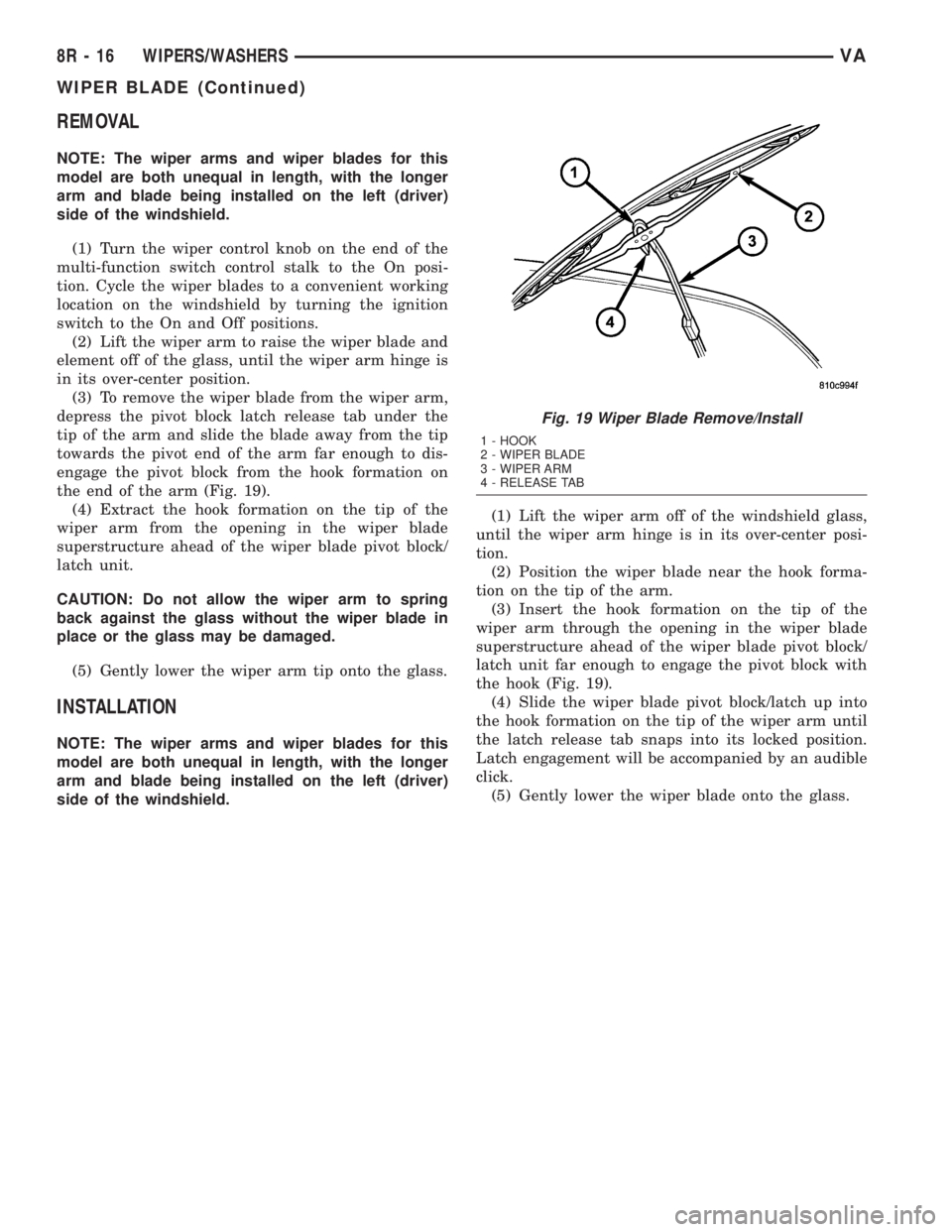
REMOVAL
NOTE: The wiper arms and wiper blades for this
model are both unequal in length, with the longer
arm and blade being installed on the left (driver)
side of the windshield.
(1) Turn the wiper control knob on the end of the
multi-function switch control stalk to the On posi-
tion. Cycle the wiper blades to a convenient working
location on the windshield by turning the ignition
switch to the On and Off positions.
(2) Lift the wiper arm to raise the wiper blade and
element off of the glass, until the wiper arm hinge is
in its over-center position.
(3) To remove the wiper blade from the wiper arm,
depress the pivot block latch release tab under the
tip of the arm and slide the blade away from the tip
towards the pivot end of the arm far enough to dis-
engage the pivot block from the hook formation on
the end of the arm (Fig. 19).
(4) Extract the hook formation on the tip of the
wiper arm from the opening in the wiper blade
superstructure ahead of the wiper blade pivot block/
latch unit.
CAUTION: Do not allow the wiper arm to spring
back against the glass without the wiper blade in
place or the glass may be damaged.
(5) Gently lower the wiper arm tip onto the glass.
INSTALLATION
NOTE: The wiper arms and wiper blades for this
model are both unequal in length, with the longer
arm and blade being installed on the left (driver)
side of the windshield.(1) Lift the wiper arm off of the windshield glass,
until the wiper arm hinge is in its over-center posi-
tion.
(2) Position the wiper blade near the hook forma-
tion on the tip of the arm.
(3) Insert the hook formation on the tip of the
wiper arm through the opening in the wiper blade
superstructure ahead of the wiper blade pivot block/
latch unit far enough to engage the pivot block with
the hook (Fig. 19).
(4) Slide the wiper blade pivot block/latch up into
the hook formation on the tip of the wiper arm until
the latch release tab snaps into its locked position.
Latch engagement will be accompanied by an audible
click.
(5) Gently lower the wiper blade onto the glass.
Fig. 19 Wiper Blade Remove/Install
1 - HOOK
2 - WIPER BLADE
3 - WIPER ARM
4 - RELEASE TAB
8R - 16 WIPERS/WASHERSVA
WIPER BLADE (Continued)
Page 316 of 1232
INSTALLATION
(1) Select a wire from the terminal repair kit that
best matches the color and gage of the wire being
repaired.
(2) Cut the repair wire to the proper length and
remove one±half (1/2) inch of insulation.
(3) Splice the repair wire to the wire harness (see
wire splicing procedure).
(4) Insert the repaired wire into the connector.
(5) Install the connector locking wedge, if required,
and reconnect the connector to its mating half/compo-
nent.
(6) Re-tape the wire harness starting at 1±1/2
inches behind the connector and 2 inches past the
repair.
(7) Connect battery and test all affected systems.
WIRE
STANDARD PROCEDURE - WIRE SPLICING
When splicing a wire, it is important that the cor-
rect gage be used as shown in the wiring diagrams.
(1) Remove one-half (1/2) inch of insulation from
each wire that needs to be spliced.
(2) Place a piece of adhesive lined heat shrink tub-
ing on one side of the wire. Make sure the tubing will
be long enough to cover and seal the entire repair
area.
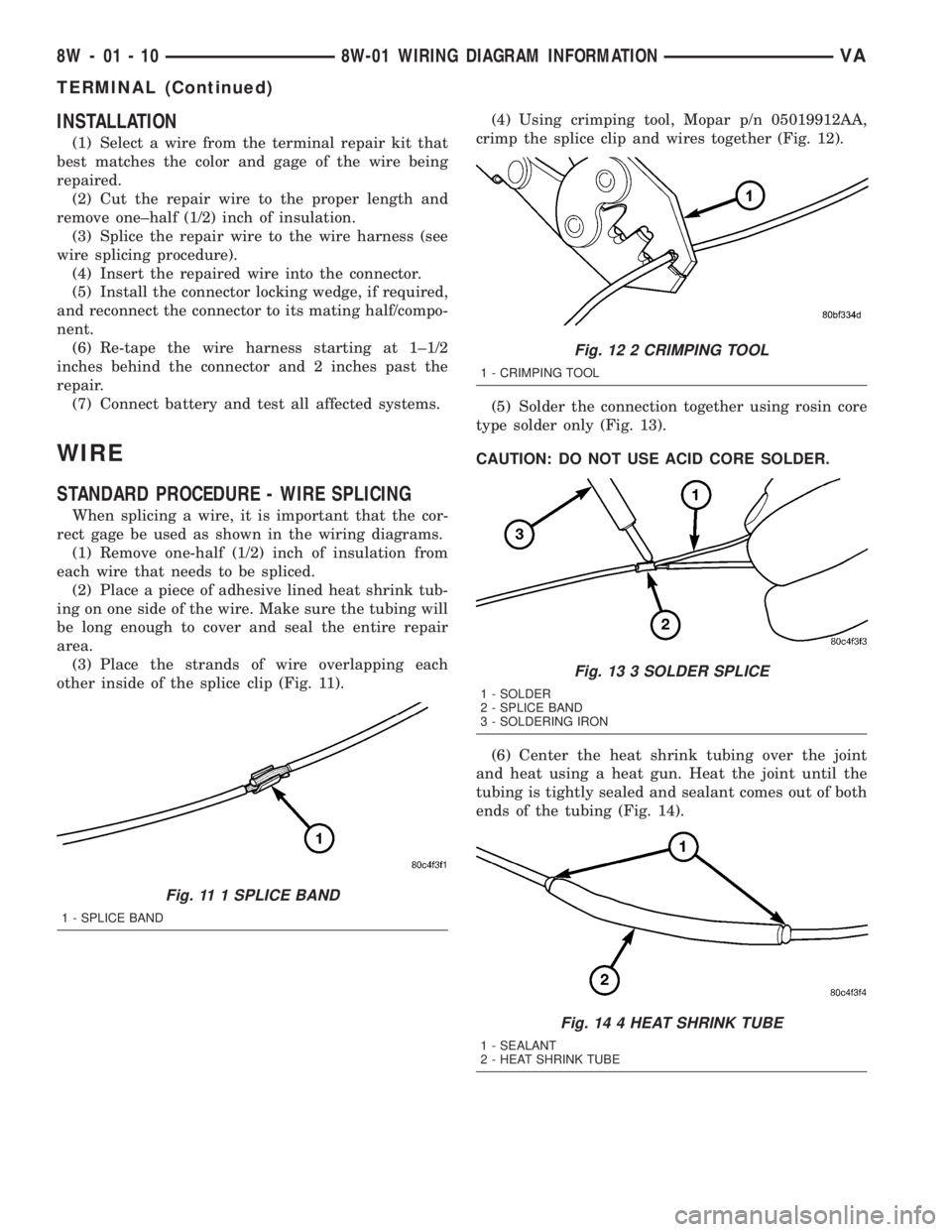
(3) Place the strands of wire overlapping each
other inside of the splice clip (Fig. 11).(4) Using crimping tool, Mopar p/n 05019912AA,
crimp the splice clip and wires together (Fig. 12).
(5) Solder the connection together using rosin core
type solder only (Fig. 13).
CAUTION: DO NOT USE ACID CORE SOLDER.
(6) Center the heat shrink tubing over the joint
and heat using a heat gun. Heat the joint until the
tubing is tightly sealed and sealant comes out of both
ends of the tubing (Fig. 14).
Fig. 11 1 SPLICE BAND
1 - SPLICE BAND
Fig. 12 2 CRIMPING TOOL
1 - CRIMPING TOOL
Fig. 13 3 SOLDER SPLICE
1 - SOLDER
2 - SPLICE BAND
3 - SOLDERING IRON
Fig. 14 4 HEAT SHRINK TUBE
1 - SEALANT
2 - HEAT SHRINK TUBE
8W - 01 - 10 8W-01 WIRING DIAGRAM INFORMATIONVA
TERMINAL (Continued)
Page 759 of 1232
(7) Connect negative battery cable.
CYLINDER HEAD
STANDARD PROCEDURE
STANDARD PROCEDURE - CYLINDER HEAD
BOLT INSPECTION
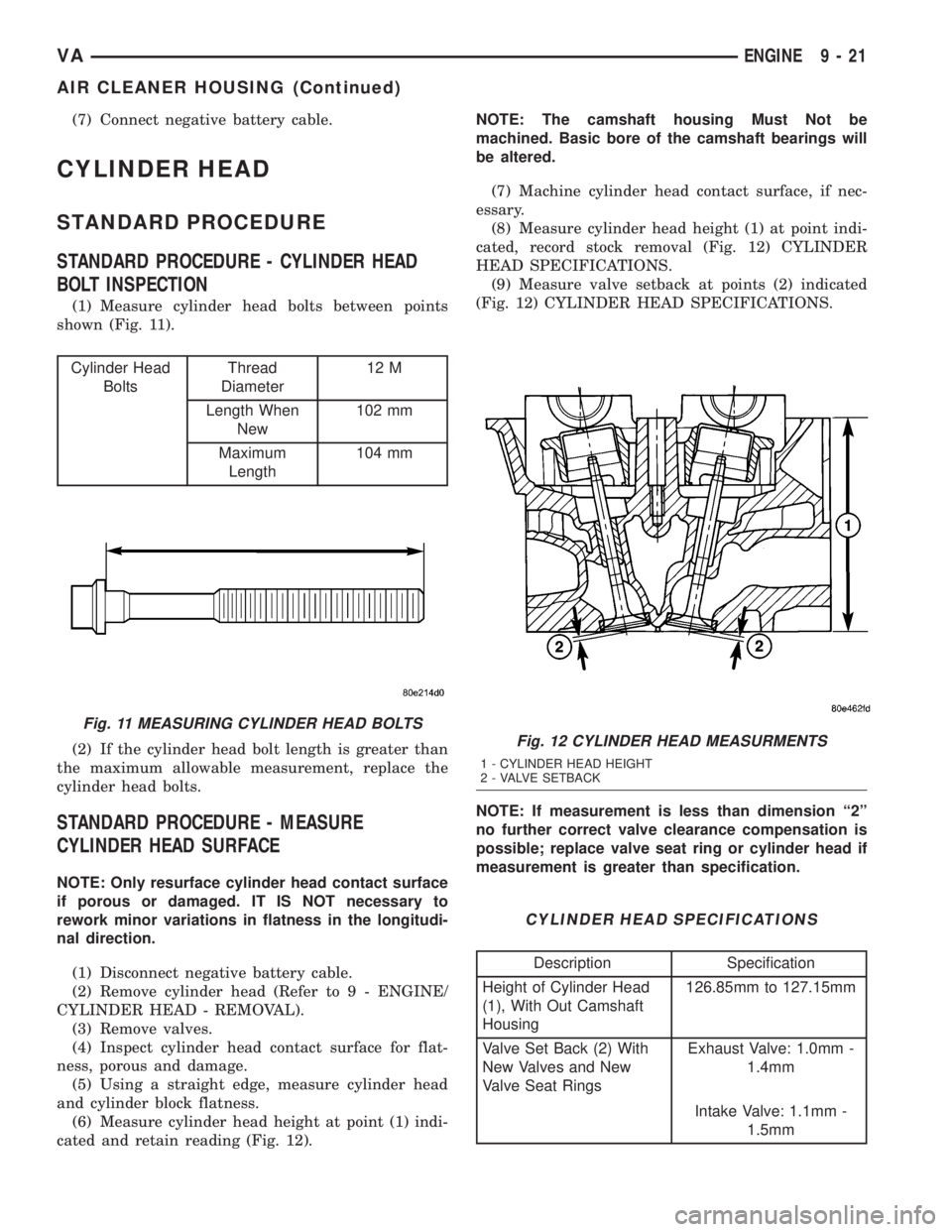
(1) Measure cylinder head bolts between points
shown (Fig. 11).
Cylinder Head
BoltsThread
Diameter12 M
Length When
New102 mm
Maximum
Length104 mm
(2) If the cylinder head bolt length is greater than
the maximum allowable measurement, replace the
cylinder head bolts.
STANDARD PROCEDURE - MEASURE
CYLINDER HEAD SURFACE
NOTE: Only resurface cylinder head contact surface
if porous or damaged. IT IS NOT necessary to
rework minor variations in flatness in the longitudi-
nal direction.
(1) Disconnect negative battery cable.
(2) Remove cylinder head (Refer to 9 - ENGINE/
CYLINDER HEAD - REMOVAL).
(3) Remove valves.
(4) Inspect cylinder head contact surface for flat-
ness, porous and damage.
(5) Using a straight edge, measure cylinder head
and cylinder block flatness.
(6) Measure cylinder head height at point (1) indi-
cated and retain reading (Fig. 12).NOTE: The camshaft housing Must Not be
machined. Basic bore of the camshaft bearings will
be altered.
(7) Machine cylinder head contact surface, if nec-
essary.
(8) Measure cylinder head height (1) at point indi-
cated, record stock removal (Fig. 12) CYLINDER
HEAD SPECIFICATIONS.
(9) Measure valve setback at points (2) indicated
(Fig. 12) CYLINDER HEAD SPECIFICATIONS.
NOTE: If measurement is less than dimension ª2º
no further correct valve clearance compensation is
possible; replace valve seat ring or cylinder head if
measurement is greater than specification.
CYLINDER HEAD SPECIFICATIONS
Description Specification
Height of Cylinder Head
(1), With Out Camshaft
Housing126.85mm to 127.15mm
Valve Set Back (2) With
New Valves and New
Valve Seat RingsExhaust Valve: 1.0mm -
1.4mm
Intake Valve: 1.1mm -
1.5mm
Fig. 11 MEASURING CYLINDER HEAD BOLTS
Fig. 12 CYLINDER HEAD MEASURMENTS
1 - CYLINDER HEAD HEIGHT
2 - VALVE SETBACK
VAENGINE 9 - 21
AIR CLEANER HOUSING (Continued)
Page 780 of 1232
CONNECTING ROD SPECIFICATIONS
Distance between middle
connecting rod bore to
connecting rod bushing
bore148.970 mm to 149.030
mm
Width of connecting rod
bearing bore at
connecting rod bushing
bore21.940 mm to 22 mm
Connecting rod bearing
shell basic bore51.600 mm to 51.614
mm
Allowable out-of-
roundness and taper of
basic bore.020 mm
Allowable twist of
connecting rod bearing
bore to connecting rod
bushing bore over a
length of 100 mm.100 mm
Allowable variation of
axial parallelism of
connecting rod bearing
bore to connecting rod
bushing bore over a
length of 100 mm.045 mm
Allowable difference in
weight of complete
connecting rod of an
engine2g
Connecting rod inner
bushing30.018 to 30.024 mm
Connecting rod outer
bushing32.575 mm to 32.600
mm
Connecting rod basic
bore32.500 mm to 32.525
mm
Piston pin play in
connecting rod.018 mm to .024 mm
Peak-to-Valley height
(Rz) of connecting rod
bushing on inside5
Connecting rod bolt
threadM8x1
STANDARD PROCEDURE - MEASURING
PISTON PROTRUSION
After replacing the pistons/connecting rods or
machining the engine block contact surface, it is then
necessary to measure the piston protrusion.
Measure protrusion between piston crown and cyl-
inder head contact surface without the head gasket
installed. The measurment must be carried out inthe direction of the piston pin in order to eliminate
piston rock.
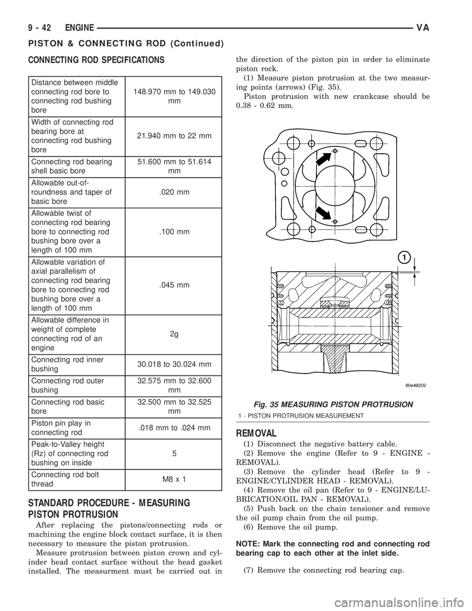
(1) Measure piston protrusion at the two measur-
ing points (arrows) (Fig. 35).
Piston protrusion with new crankcase should be
0.38 - 0.62 mm.
REMOVAL
(1) Disconnect the negative battery cable.
(2) Remove the engine (Refer to 9 - ENGINE -
REMOVAL).
(3) Remove the cylinder head (Refer to 9 -
ENGINE/CYLINDER HEAD - REMOVAL).
(4) Remove the oil pan (Refer to 9 - ENGINE/LU-
BRICATION/OIL PAN - REMOVAL).
(5) Push back on the chain tensioner and remove
the oil pump chain from the oil pump.
(6) Remove the oil pump.
NOTE: Mark the connecting rod and connecting rod
bearing cap to each other at the inlet side.
(7) Remove the connecting rod bearing cap.
Fig. 35 MEASURING PISTON PROTRUSION
1 - PISTON PROTRUSION MEASUREMENT
9 - 42 ENGINEVA
PISTON & CONNECTING ROD (Continued)