Page 44 of 969
550DH-02
I31635
Radiator Support Upper
O-ring �
Cooler Condenser Assy
Cooler Dryer
Filter
Cap
9.8 (100, 85 in.Vlbf)
Non-reusable parts Compressor oil ND-OIL 8 or equivalent
9.8 (100, 85 in.Vlbf)
O-ring �5.4 (55, 47 in.Vlbf)
O-ring �
12 (125, 9)
�
Air Cleaner Inlet No. 1
Air Cleaner Inlet Assy
NVm (kgfVcm, ftVlbf): Specified torque
Radiator Lower Air Deflector
Hood Lock Release Lever
Protector
55-44
- HEATER & AIR CONDITIONERCOOLER CONDENSER ASSY
2659 Author�: Date�:
2005 LEXUS ES330 REPAIR MANUAL (RM1124U)
COMPONENTS
Page 46 of 969
I30086
10 mm
(0.39 in.)
Hexagon
Wrench
Modulator
E50132
E57114
E50386
E50132
I30086
10 mm
(0.39 in.)
Hexagon
Wrench
Modulator
55-46
- HEATER & AIR CONDITIONERCOOLER CONDENSER ASSY
2661 Author�: Date�:
2005 LEXUS ES330 REPAIR MANUAL (RM1124U)
7. REMOVE COOLER DRYER
(a) Using hexagon wrench 10 mm (0.39 in.), remove the cap
and filter from the modulator.
(b) Remove the 2 O-rings from the cap.
(c) Using a needle nose pliers, remove the cooler dryer.
8. INSTALL COOLER DRYER
(a) Using a needle nose pliers, install the cooler dryer.
(b) Install 2 new O-rings to the cap.
(c) Sufficiently apply compressor oil to the fit surfaces of the
O-ring and the cap.
Compressor oil: ND-OIL 8 or equivalent
(d) Using hexagon wrench 10 mm (0.39 in.), install the cap
to the condenser assy.
Torque: 12 NVm (125 kgfVcm, 9 ftVlbf)
Page 377 of 969

14-1
2093 Author�: Date�:
2005 LEXUS ES330 REPAIR MANUAL")
141C0-02
A82940
Vane Pump
CrankshaftGenerator Measuring Points for Belt Deflection
or Tension
Compressor
- ENGINE MECHANICALENGINE (3MZ-FE)
14-1
2093 Author�: Date�:
2005 LEXUS ES330 REPAIR MANUAL (RM1124U)
ENGINE (3MZ-FE)
INSPECTION
1. INSPECT ENGINE COOLANT (See page 16-1)
2. INSPECT ENGINE OIL
3. INSPECT BATTERY
Standard specific gravity: 1.25 to 1.29 at 20�C (68�F)
4. INSPECT AIR CLEANER FILTER ELEMENT SUB-ASSY
5. INSPECT SPARK PLUG (See page 18-3)
6. INSPECT V-RIBBED BELT
(a) Belt deflection:
Pressing force: 98 N (10 kgf, 22 lbf)
New Belt
mm (in.)Used Belt
mm (in.)
V-ribbed Belt
(For fan and generator)9.1 to 10.5
(0.358 to 0.413)11 to 13.5
(0.433 to 0.531)
V-ribbed Belt
(For vane pump)8 to 10
(0.315 to 0.394)11 to 14
(0.433 to 0.551)
(b) Belt tension:
New Belt
N (kg , lb)Used Belt
N (kg , lb)
V-ribbed Belt
(For fan and generator)637 to 735
(65 to 75 , 143 to 165)392 to 588
(40 to 60 , 88 to 132)
V-ribbed Belt
(For vane pump)588 to 686
(60 to 70 , 132 to 154)245 to 392
(25 to 40 , 55 to 88)
NOTICE:
�Check the drive belt deflection at the specified point.
�When installing a new belt, set its tension value as
specified.
�When inspecting a belt which is used for over 5 min-
utes, apply the specification of ºUsed beltº.
�When reinstalling a belt which is used for over 5 min-
utes, adjust its belt deflection and tension to the inter-
mediate value of each specification in ºUsed beltº.
�The V- ribbed belt tension and deflection value
should be checked after 2 revolutions of engine
cranking.
�When using a belt tension gauge, confirm the accura-
cy first by using a master gauge.
7. INSPECT IGNITION TIMING
(a) Warm up engine.
(b) When using the hand-held tester or OBD II scan tool:
(1) Connect the hand-held tester or OBD II scan tool
to the DLC3.
(2) Enter DATA LIST MODE on the hand-held tester or
OBD II scan tool.
Ignition timing: 8 to 12� BTDC
HINT:
Refer to the hand-held tester or OBD II scan tool operator's
manual if you need help to select DATA LIST.
Page 402 of 969
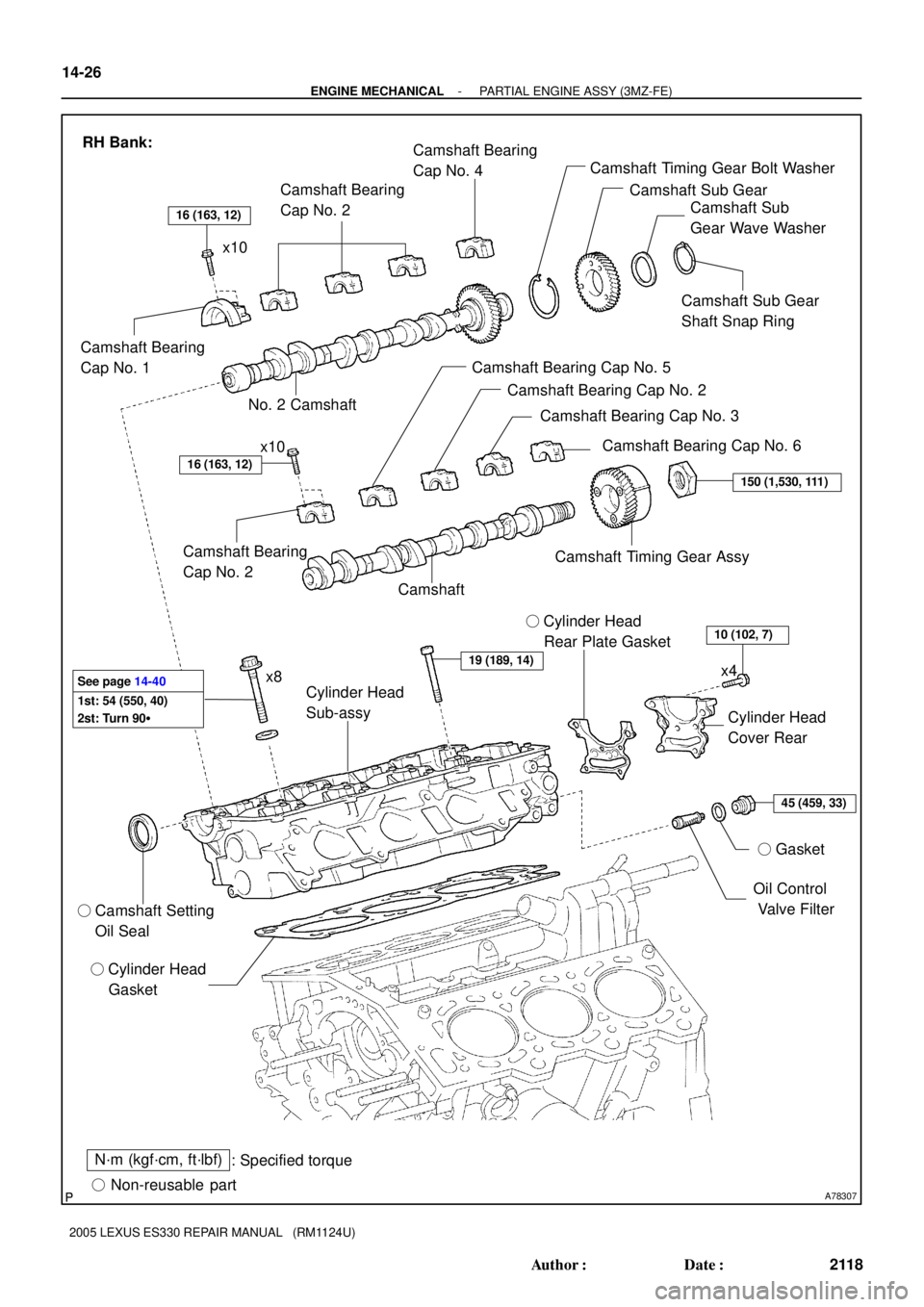
A78307
N´m (kgf´cm, ft´lbf)
: Specified torque
� Non-reusable part � Camshaft Setting
Oil Seal� Gasket
45 (459, 33)
10 (102, 7)
19 (189, 14)
150 (1,530, 111)
16 (163, 12)
� Cylinder Head
GasketOil Control
Valve Filter Cylinder Head
Cover Rear Cylinder Head
Sub-assy� Cylinder Head
Rear Plate Gasket Camshaft Bearing
Cap No. 2
CamshaftCamshaft Timing Gear Assy RH Bank:
Camshaft Bearing
Cap No. 1Camshaft Bearing
Cap No. 2Camshaft Bearing
Cap No. 4
No. 2 CamshaftCamshaft Bearing Cap No. 5
Camshaft Bearing Cap No. 2
Camshaft Bearing Cap No. 3
Camshaft Bearing Cap No. 6 Camshaft Timing Gear Bolt Washer
Camshaft Sub Gear
Camshaft Sub
Gear Wave Washer
Camshaft Sub Gear
Shaft Snap Ring x10
x4
x10
16 (163, 12)
1st: 54 (550, 40)
2st: Turn 90� See page 14-40
x8 14-26
- ENGINE MECHANICALPARTIAL ENGINE ASSY (3MZ-FE)
2118 Author�: Date�:
2005 LEXUS ES330 REPAIR MANUAL (RM1124U)
Page 403 of 969
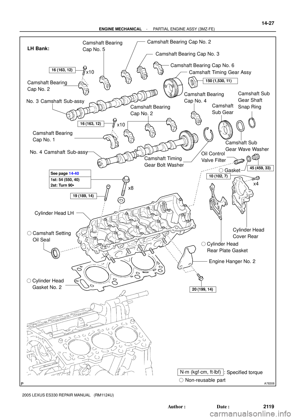
A78308
� Camshaft Setting
Oil Seal
� Cylinder Head
Gasket No. 2Cylinder Head
Cover Rear
� Cylinder Head
Rear Plate Gasket Camshaft Bearing
Cap No. 2
Camshaft Bearing
Cap No. 1Camshaft Bearing Cap No. 2
Camshaft Bearing
Cap No. 4 Camshaft Bearing
Cap No. 5
Camshaft Bearing
Cap No. 2Camshaft Bearing Cap No. 3
Camshaft Bearing Cap No. 6
Camshaft Timing
Gear Bolt WasherCamshaft
Sub Gear
Camshaft Sub
Gear Wave WasherCamshaft Sub
Gear Shaft
Snap Ring
16 (163, 12)
N´m (kgf´cm, ft´lbf)
: Specified torque
� Non-reusable part
LH Bank:
Camshaft Timing Gear Assy
� Gasket
No. 4 Camshaft Sub-assy
No. 3 Camshaft Sub-assy
Oil Control
Valve Filter
x4
150 (1,530, 11)
45 (459, 33)
16 (163, 12)
19 (189, 14)
Engine Hanger No. 2
Cylinder Head LH
20 (199, 14)
1st: 54 (550, 40)
2st: Turn 90� See page 14-4010 (102, 7)
x8 x10 x10
- ENGINE MECHANICALPARTIAL ENGINE ASSY (3MZ-FE)
14-27
2119 Author�: Date�:
2005 LEXUS ES330 REPAIR MANUAL (RM1124U)
Page 404 of 969
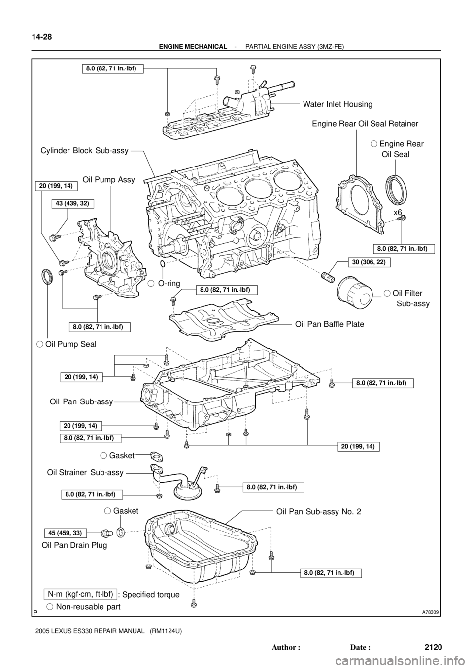
A78309
N´m (kgf´cm, ft´lbf)
: Specified torque
� Non-reusable part� O-ring
� Gasket
8.0 (82, 71 in.Vlbf)
8.0 (82, 71 in.Vlbf)
45 (459, 33)
8.0 (82, 71 in.Vlbf)
8.0 (82, 71 in.Vlbf)
8.0 (82, 71 in.Vlbf)
8.0 (82, 71 in.Vlbf)
30 (306, 22)
43 (439, 32)
20 (199, 14)
8.0 (82, 71 in.Vlbf)
20 (199, 14)
8.0 (82, 71 in.Vlbf)
8.0 (82, 71 in.Vlbf)
20 (199, 14)
Oil Pan Sub-assy No. 2 � Gasket Oil Strainer Sub-assy
Oil Pan Drain PlugOil Pan Sub-assy � Oil Pump SealOil Pan Baffle Plate� Oil Filter
Sub-assyx6 Water Inlet Housing
Engine Rear Oil Seal Retainer
� Engine Rear
Oil Seal Cylinder Block Sub-assy
20 (199, 14)
Oil Pump Assy
14-28
- ENGINE MECHANICALPARTIAL ENGINE ASSY (3MZ-FE)
2120 Author�: Date�:
2005 LEXUS ES330 REPAIR MANUAL (RM1124U)
Page 423 of 969
A78715
SST
A52353
A05275
A78716
Front
- ENGINE MECHANICALPARTIAL ENGINE ASSY (3MZ-FE)
14-47
2139 Author�: Date�:
2005 LEXUS ES330 REPAIR MANUAL (RM1124U)
(b) Using SST, turn the sub gear counterclockwise, then re-
move the service bolt.
SST 09960-10010 (09962-01000, 09963-00500)
(c) Using snap ring pliers, remove the snap ring.
(d) Remove the wave washer, camshaft sub gear and cam-
shaft gear bolt washer.
HINT:
Arrange the camshaft sub gears and gear bolt washers (RH and
LH sides) so that they can be returned to the original locations
when reassembling.
34. REMOVE ENGINE HANGER NO.2
35. REMOVE CYLINDER HEAD COVER REAR
36. REMOVE OIL CONTROL VALVE FILTER
(a) Remove the plug, gasket and valve filter.
37. REMOVE CYLINDER HEAD SUB-ASSY
(a) Using a socket hexagon wrench 8, remove the hexagon
bolt.
Page 425 of 969
A78720
SST
A36750
A00019
SST
SST
B04136
- ENGINE MECHANICALPARTIAL ENGINE ASSY (3MZ-FE)
14-49
2141 Author�: Date�:
2005 LEXUS ES330 REPAIR MANUAL (RM1124U)
42. REMOVE OIL FILTER SUB-ASSY
(a) Using SST, remove the oil filter.
SST 09228-07501
(b) Using a socket hexagon wrench 12, remove the oil filter
union.
43. REMOVE OIL PAN DRAIN PLUG
44. REMOVE OIL PAN SUB-ASSY NO.2
(a) Remove the 10 bolts and 2 nuts.
(b) Insert the blade of SST between the oil pan No. 1 and oil
pan No. 2, then cut off the sealer and remove the oil pan
No. 2.
SST 09032-00100
NOTICE:
�Be careful not to damage the contact surface of the oil
pan No. 1 where the oil pan No. 2 is mounted.
�Do not damage the flange portion of the oil pan No. 2
when removing.
45. REMOVE OIL STRAINER SUB-ASSY
(a) Remove the bolt and 2 nuts, then remove the oil strainer and gasket.
46. REMOVE OIL PAN SUB-ASSY
(a) Loosen and remove the 15 bolts and 2 nuts uniformly.