Page 726 of 969

or less 51-4
- POWER STEERINGPOWER STEERING SYSTEM
2579 Author�: Date�:
(c) Start the engine and run it at idle.
(d) Turn the st")
F40897
NormalAbnormal
R11786Engine Idling Engine Stopped5 mm (0.20 in.)
or less 51-4
- POWER STEERINGPOWER STEERING SYSTEM
2579 Author�: Date�:
(c) Start the engine and run it at idle.
(d) Turn the steering wheel from lock to lock several times to
raise fluid temperature.
Fluid temperature: 75 - 80°C (167 - 176°F)
(e) Check for foaming or emulsification.
If foaming or emulsification is identified, bleed the power steer-
ing system.
(f) With the engine idling, measure the fluid level in the oil
reservoir.
(g) Stop the engine.
(h) Wait a few minutes and remeasure the fluid level in the oil
reservoir.
Maximum fluid level rise: 5 mm (0.20 in.)
If a problem is found, bleed the power steering system.
(i) Check the fluid level.
4. CHECK STEERING FLUID PRESSURE
(a) Disconnect the pressure feed tube assy from the rack &
pinion power steering gear assy (See page 51-21).
(b) Connect SST, as shown in the illustration.
SST 09640-10010 (09641-01010, 09641-01020,
09641-01030)
NOTICE:
Check that the valve of the SST is in the open position.
(c) Bleed the power steering system.
(d) Start the engine and run it at idle.
(e) Turn the steering wheel from lock to lock several times to
raise fluid temperature.
Fluid temperature: 75 - 80 °C (167 - 176 °F)
Page 727 of 969

F41520
SST
OUT Attachment
Pressure Feed
Tube AssyAttachment
IN
Z15498
Oil
Reservoir
PS Vane
Pump PS Gear
SST Closed
Z15499
Oil
Reservoir
PS Vane
Pump PS Gear
SST Open
Z15500
Oil
Reservoir
PS Vane
Pump PS Gear
SST Open Lock Position
- POWER STEERINGPOWER STEERING SYSTEM
51-5
2580 Author�: Date�:
(f) With the engine idling, close the valve of the SST and ob-
serve the reading on the SST.
Fluid pressure:
7,800 - 8,300 kPa (80 - 85 kgf/cm
2, 1,138 - 1,209 psi)
NOTICE:
�Do not keep the valve closed for more than 10 se-
conds.
�Do not let the fluid temperature become too high.
(g) With the engine idling, open the valve fully.
(h) Measure the fluid pressure at engine speeds of 1,000 rpm
and 3,000 rpm.
Fluid pressure difference:
490 kPa (5 kgf/cm
2, 71 psi) or less
NOTICE:
Do not turn the steering wheel.
(i) With the engine idling and valve fully opened, turn the
steering wheel to full lock position.
Fluid pressure:
7,800 - 8,300 kPa (80 - 85 kgf/cm
2, 1,138 - 1,209 psi)
NOTICE:
�Do not maintain lock position for more than 10 se-
conds.
�Do not let the fluid temperature become too high.
Page 728 of 969
F41590
51-6
- POWER STEERINGPOWER STEERING SYSTEM
2581 Author�: Date�:
(j) Disconnect the SST.
SST 09640- 10010 (09641- 01010, 09641- 01020,
09641-01030)
(k) Connect the pressure feed tube assy to the rack & pinion
power steering gear assy (See page 51-21).
(l) Bleed the power steering system.
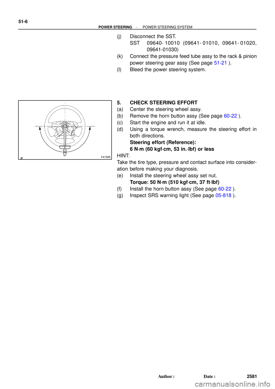
5. CHECK STEERING EFFORT
(a) Center the steering wheel assy.
(b) Remove the horn button assy (See page 60-22).
(c) Start the engine and run it at idle.
(d) Using a torque wrench, measure the steering effort in
both directions.
Steering effort (Reference):
6 N´m (60 kgf´cm, 53 in.´lbf) or less
HINT:
Take the tire type, pressure and contact surface into consider-
ation before making your diagnosis.
(e) Install the steering wheel assy set nut.
Torque: 50 N´m (510 kgf´cm, 37 ft´lbf)
(f) Install the horn button assy (See page 60-22).
(g) Inspect SRS warning light (See page 05-818).
Page 729 of 969
51068-01
F41597
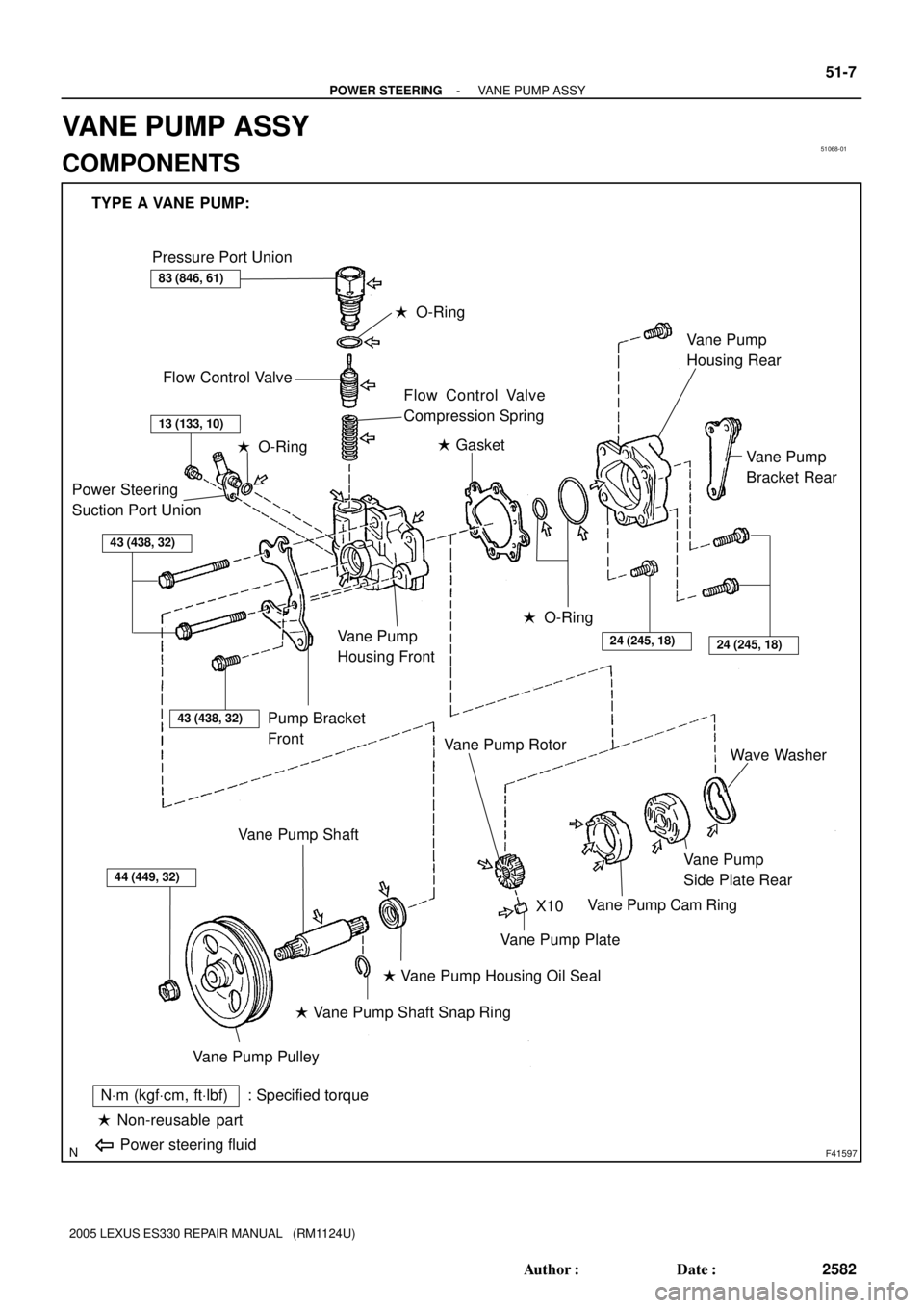
TYPE A VANE PUMP:
Pressure Port Union
Flow Control Valve
� O-Ring
Flow Control Valve
Compression Spring
Power Steering
Suction Port Union
43 (438, 32)
Pump Bracket
Front
Vane Pump
Housing Front
� O-Ring� Gasket
� O-Ring
24 (245, 18)24 (245, 18)
Vane Pump
Bracket Rear Vane Pump
Housing Rear
44 (449, 32)
Vane Pump Pulley
Vane Pump Shaft
� Vane Pump Shaft Snap Ring
� Vane Pump Housing Oil Seal
Vane Pump Plate
Vane Pump Rotor
Vane Pump Cam Ring
Vane Pump
Side Plate RearWave Washer
� Non-reusable part
NVm (kgfVcm, ftVlbf) : Specified torque
Power steering fluid
X10
83 (846, 61)
13 (133, 10)
43 (438, 32)
- POWER STEERINGVANE PUMP ASSY
51-7
2582 Author�: Date�:
2005 LEXUS ES330 REPAIR MANUAL (RM1124U)
VANE PUMP ASSY
COMPONENTS
Page 730 of 969
F41589
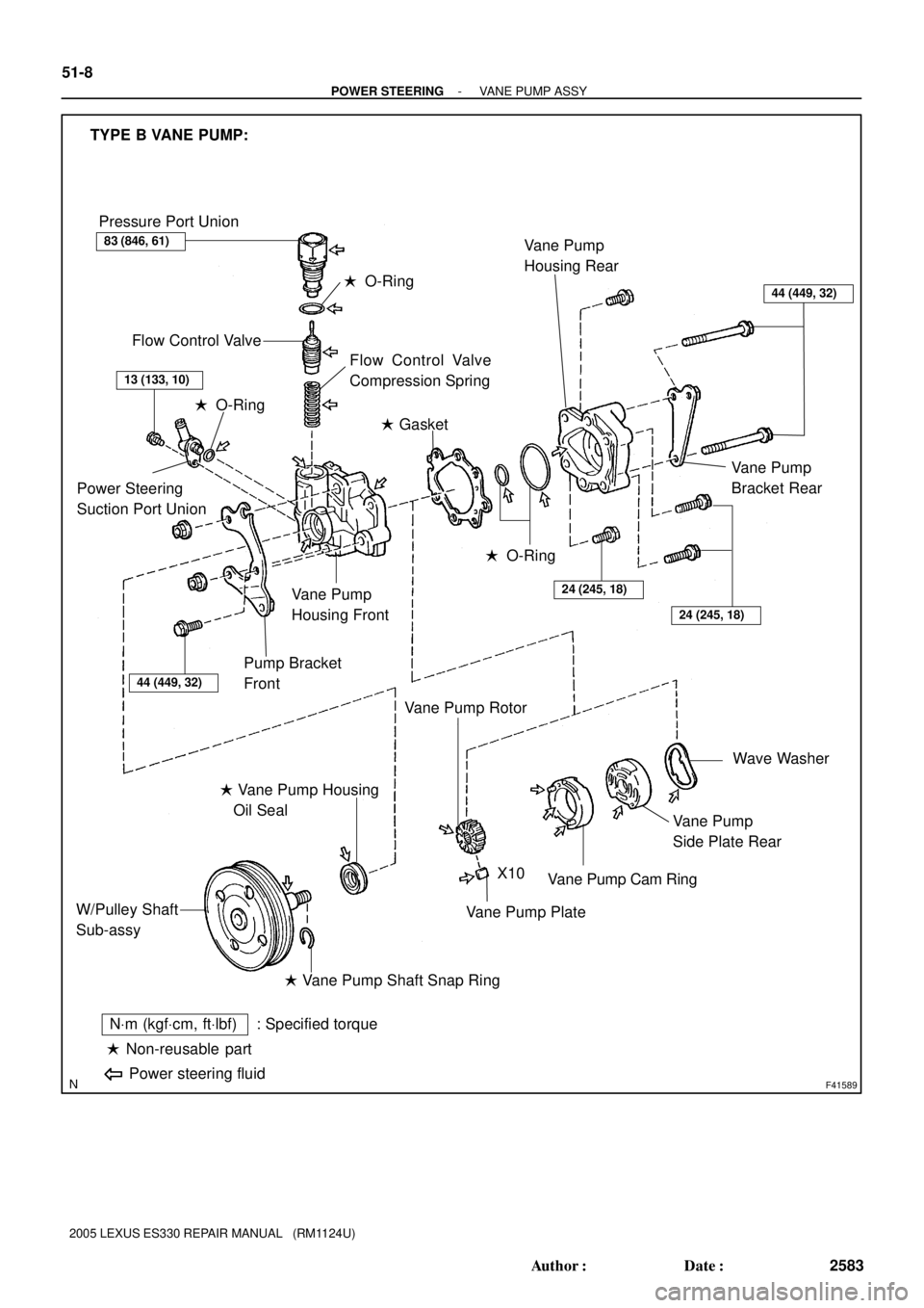
TYPE B VANE PUMP:
Pressure Port Union
� O-Ring
Flow Control Valve
Flow Control Valve
Compression Spring
� Gasket
Power Steering
Suction Port Union
� O-Ring
Pump Bracket
Front
Vane Pump
Housing Front
� O-Ring
24 (245, 18)
24 (245, 18)
Vane Pump
Housing Rear
Wave Washer
Vane Pump
Side Plate Rear
Vane Pump Cam Ring
Vane Pump Plate
� Vane Pump Shaft Snap Ring W/Pulley Shaft
Sub-assy� Vane Pump Housing
Oil Seal
� Non-reusable part
NVm (kgfVcm, ftVlbf) : Specified torque
Power steering fluid
Vane Pump
Bracket Rear
X10
Vane Pump Rotor
83 (846, 61)
13 (133, 10)
44 (449, 32)
44 (449, 32)
51-8
- POWER STEERINGVANE PUMP ASSY
2583 Author�: Date�:
2005 LEXUS ES330 REPAIR MANUAL (RM1124U)
Page 731 of 969

OVERHAUL
NOTICE:
�When using a vise, do not over tighten.
�When installing, c")
51069-02
F41598
F41599
- POWER STEERINGVANE PUMP ASSY
51-9
2584 Author�: Date�:
2005 LEXUS ES330 REPAIR MANUAL (RM1124U)
OVERHAUL
NOTICE:
�When using a vise, do not over tighten.
�When installing, coat the parts indicated by the arrows with power steering fluid
(See page 51-7).
1. REMOVE FRONT WHEEL RH
2. DRAIN POWER STEERING FLUID
3. REMOVE FRONT FENDER LINER RH
4. REMOVE FRONT FENDER APRON SEAL RH
5. DISCONNECT OIL RESERVOIR TO PUMP HOSE NO.1
(a) Remove the clip and disconnect the oil reservoir to pump hose No.1.
NOTICE:
Take care not to spill fluid on the V belt.
6. REMOVE POWER STEERING OIL PRESSURE SWITCH
(a) Disconnect the connector.
(b) Remove the oil power steering pressure switch from the union bolt.
NOTICE:
Be careful not to drop the oil power steering pressure switch.
If the oil power steering pressure switch is dropped or strongly damaged, replace it with a new one.
7. DISCONNECT PRESSURE FEED HOSE
(a) Using a spanner (22 mm) to hold the pressure port union,
remove the union bolt and gasket.
8. REMOVE VANE PUMP V BELT
(a) Loosen the 2 bolts and remove the vane pump V belt.
9. REMOVE VANE PUMP ASSY
(a) Remove the 2 bolts and vane pump assy.
Page 732 of 969

10. REMOVE VANE PUMP PULLEY(TYPE A VANE PUMP)
(a) Using SST, stop the vane pump p")
F41600
SST
C65312
51-10
- POWER STEERINGVANE PUMP ASSY
2585 Author�: Date�:
2005 LEXUS ES330 REPAIR MANUAL (RM1124U)
10. REMOVE VANE PUMP PULLEY(TYPE A VANE PUMP)
(a) Using SST, stop the vane pump pulley rotation and loosen
the nut.
SST 09960-10010 (09962-01000, 09963-01000)
(b) Remove the nut and vane pump pulley from the vane
pump shaft.
11. REMOVE POWER STEERING SUCTION PORT UNION
(a) Remove the bolt and power steering suction port union.
(b) Remove the O-ring from the power steering suction port union.
12. REMOVE PRESSURE PORT UNION
(a) Remove the pressure port union.
(b) Remove the O-ring from the pressure port union.
13. REMOVE FLOW CONTROL VALVE
14. REMOVE FLOW CONTROL VALVE COMPRESSION SPRING
15. REMOVE VANE PUMP BRACKET REAR(TYPE A VANE PUMP)
(a) Remove the 2 bolts and vane pump bracket rear from the vane pump assy.
16. REMOVE VANE PUMP BRACKET REAR(TYPE B VANE PUMP)
(a) Remove the 2 bolts, 2 nuts and vane pump bracket rear from the vane pump assy.
17. REMOVE VANE PUMP HOUSING REAR
(a) Remove the 4 bolts and vane pump housing rear from the vane pump housing front.
(b) Remove the gasket.
(c) Remove the 2 O-rings from the vane pump housing rear.
18. REMOVE VANE PUMP SIDE PLATE REAR
(a) Remove the wave washer from the vane pump side plate rear.
(b) Remove the vane pump side plate rear.
19. REMOVE VANE PUMP CAM RING
20. REMOVE VANE PUMP ROTOR
(a) Remove the 10 vane pump plates from the vane pump ro-
tor.
(b) Using a screwdriver, remove the vane pump shaft snap
ring.
(c) Remove the vane pump rotor.
21. REMOVE VANE PUMP SHAFT(TYPE A VANE PUMP)
22. REMOVE W/PULLEY SHAFT SUB-ASSY(TYPE B VANE PUMP)
Page 733 of 969
F41486
SST
F41618
Caliper Gauge
Micrometer
Vane Pump
Shaft
Bushing
Vane Pump Housing Front
Vane Pump
Housing FrontBushing
TYPE A VANE PUMP
TYPE B VANE PUMP
W/Pulley Shaft
Sub-assy
- POWER STEERINGVANE PUMP ASSY
51-1 1
2586 Author�: Date�:
2005 LEXUS ES330 REPAIR MANUAL (RM1124U)
23. REMOVE PUMP BRACKET FRONT
(a) Remove the bolt and pump bracket front from the vane pump housing front.
24. REMOVE VANE PUMP HOUSING OIL SEAL
(a) Using SST and a hammer, tap out the vane pump housing
oil seal from the vane pump housing front.
SST 09631-10030
NOTICE:
Be careful not to damage the bushing of the vane pump
housing front.
25. INSPECT OIL CLEARANCE
(a) Using a micrometer and a caliper gauge, measure the oil
clearance.
Standard clearance:
0.027 - 0.054 mm (0.00106 - 0.00213 in.)
Maximum clearance: 0.07 mm (0.0028 in.)
If it is more than the maximum, replace the vane pump assy.