Page 734 of 969

N00372
HeightThickness
Length
R10282
Feeler Gauge
F41490
F41491F41622
Compressed Air
R08702
Vernier Calipers
51-12
- POWER STEERINGVANE PUMP ASSY
2587 Author�: Date�:
2005 LEXUS ES330 REPAIR MANUAL (RM1124U)
26. INSPECT VANE PUMP ROTOR AND VANE PUMP
PLATES
(a) Using a micrometer, measure the height, thickness and
length of the vane pump plates.
Minimum height: 8.6 mm (0.339 in.)
Minimum thickness: 1.397 mm (0.05500 in.)
Minimum length: 14.991 mm (0.59020 in.)
(b) Using a feeler gauge, measure the clearance between
the vane pump rotor groove and vane pump plate.
Maximum clearance: 0.03 mm (0.0012 in.)
If it is more than the maximum, replace the vane pump assy.
27. INSPECT FLOW CONTROL VALVE
(a) Coat the flow control valve with power steering fluid and
check that it falls smoothly into the flow control valve hole
by its own weight.
(b) Check the flow control valve for leakage. Close one of the
holes and apply compressed air of 392 - 490 kPa (4 - 5
kgf/cm
2, 57 - 71 psi) into the opposite side hole, and con-
firm that air does not come out from the end holes.
If necessary, replace the vane pump assy.
28. INSPECT FLOW CONTROL VALVE COMPRESSION
SPRING
(a) Using vernier calipers, measure the free length of the flow
control valve compression spring.
Minimum free length: 32.24 mm (1.2693 in.)
If it is not within the specification, replace the vane pump assy.
Page 735 of 969

29. INSPECT")
W03541F41624
Press
SST
Oil Seal
F40339
Power Steering Fluid
F40339
Power Steering Fluid
- POWER STEERINGVANE PUMP ASSY
51-13
2588 Author�: Date�:
2005 LEXUS ES330 REPAIR MANUAL (RM1124U)
29. INSPECT PRESSURE PORT UNION
If the union seat in the pressure port union is remarkably damaged and it may cause fluid leakage, replace
the vane pump assy.
30. INSTALL VANE PUMP HOUSING OIL SEAL
(a) Coat a new vane pump housing oil seal lip with power
steering fluid.
(b) Using SST and a press, install the new vane pump hous-
ing oil seal.
SST 09950-60010 (09951-00330),
09950-70010 (09951-07100)
NOTICE:
Make sure that the vane pump housing oil seal is installed
facing the correct direction.
31. INSTALL PUMP BRACKET FRONT
(a) Install the pump bracket front with the bolt.
Torque:
Type A Vane Pump: 43 NVm (438 kgfVcm, 32 ftVlbf)
Type B Vane Pump: 44 NVm (449 kgfVcm, 32 ftVlbf)
32. INSTALL VANE PUMP SHAFT(TYPE A VANE PUMP)
(a) Coat inside bushing surface of the vane pump housing
front with power steering fluid.
(b) Gradually insert the vane pump shaft from the pulley side.
NOTICE:
Do not damage the vane pump housing oil seal lip in the
vane pump housing front.
33. INSTALL W/PULLEY SHAFT SUB- ASSY(TYPE B
VANE PUMP)
(a) Coat inside bushing surface of the vane pump housing
front with power steering fluid.
(b) Gradually insert the w/pulley shaft sub-assy from the
pulley side.
NOTICE:
Do not damage the vane pump housing oil seal lip in the
vane pump housing front.
Page 736 of 969

34. INSTALL VANE PUMP ROTOR")
F40340
F40341
Inscribed
Mark
F04644
Round End
Gasket
F41480
Set
R11292
51-14
- POWER STEERINGVANE PUMP ASSY
2589 Author�: Date�:
2005 LEXUS ES330 REPAIR MANUAL (RM1124U)
34. INSTALL VANE PUMP ROTOR
(a) Install the vane pump rotor.
(b) Using a snap ring expander, install a new vane pump
shaft snap ring.
35. INSTALL VANE PUMP CAM RING
(a) Align the holes of the vane pump cam ring with 2 straight
pins, and install the vane pump cam ring with inscribed
mark facing outward.
(b) Coat 10 vane pump plates with power steering fluid.
(c) Install the vane pump plates with the round end facing
outward.
(d) Install a new gasket.
36. INSTALL VANE PUMP SIDE PLATE REAR
(a) Coat a new O-ring with power steering fluid and install it
to the vane pump side plate rear.
(b) Align the groove of the vane pump cam ring with that of
the vane pump side plate rear, install the vane pump side
plate rear.
(c) Install the wave washer so that its protrusions fit into the
slots in the vane pump side plate rear.
Page 737 of 969

37. INSTALL VANE PUMP HOUSING REAR
(a) Coat a new O-ring with power steering fluid an")
F41573
F41492
- POWER STEERINGVANE PUMP ASSY
51-15
2590 Author�: Date�:
2005 LEXUS ES330 REPAIR MANUAL (RM1124U)
37. INSTALL VANE PUMP HOUSING REAR
(a) Coat a new O-ring with power steering fluid and install it to the vane pump housing rear.
(b) Install the vane pump housing rear with the 4 bolts.
Torque: 24 NVm (245 kgfVcm, 18 ftVlbf)
38. MEASURE VANE PUMP ROTATION TORQUE(TYPE A
VANE PUMP)
(a) Check that the vane pump rotates smoothly without ab-
normal noise.
(b) Temporarily install the pulley set nut.
(c) Using a torque wrench, check the vane pump rotating
torque.
Rotating torque:
0.27 NVm (2.8 kgfVcm, 2.4 in.Vlbf) or less
39. MEASURE VANE PUMP ROTATION TORQUE(TYPE B
VANE PUMP)
(a) Check that the vane pump rotates smoothly without ab-
normal noise.
(b) Temporarily install the service bolt.
Recommended service bolt:
Thread diameter: 10 mm (0.39 in.)
Thread pitch: 1.25 mm (0.0492 in.)
Bolt length: 50 mm (1.97 in.)
(c) Using a torque wrench, check the vane pump rotating
torque.
Rotating torque:
0.27 NVm (2.8 kgfVcm, 2.4 in.Vlbf) or less
40. INSTALL VANE PUMP BRACKET REAR(TYPE A VANE PUMP)
(a) Install the vane pump bracket rear with the 2 bolts.
Torque: 43 NVm (438 kgfVcm, 32 ftVlbf)
41. INSTALL VANE PUMP BRACKET REAR(TYPE B VANE PUMP)
(a) Install the vane pump bracket rear with the 2 bolts and 2 nuts.
Torque: 44 NVm (449 kgfVcm, 32 ftVlbf)
42. INSTALL FLOW CONTROL VALVE COMPRESSION SPRING
(a) Coat the flow control valve compression spring with power steering fluid and install it.
(b) Install the flow control valve compression spring.
43. INSTALL FLOW CONTROL VALVE
(a) Coat the flow control valve with power steering fluid.
(b) Install the flow control valve.
44. INSTALL PRESSURE PORT UNION
(a) Coat a new O-ring with power steering fluid and install it to the pressure port union.
(b) Install the pressure port union.
Torque: 83 NVm (846 kgfVcm, 61 ftVlbf)
Page 738 of 969

45. INSTALL POWER STEERING SUCTION PORT UNI")
F41600
SST
F41599
A
B
W03441
Pressure
Feed
Hose
Stopper 51-16
- POWER STEERINGVANE PUMP ASSY
2591 Author�: Date�:
2005 LEXUS ES330 REPAIR MANUAL (RM1124U)
45. INSTALL POWER STEERING SUCTION PORT UNION
(a) Coat a new O-ring with power steering fluid and install it to the power steering suction port union.
(b) Install the power steering suction port union with the bolt.
Torque: 13 NVm (133 kgfVcm, 10 ftVlbf)
46. INSTALL VANE PUMP PULLEY(TYPE A VANE PUMP)
(a) Install the vane pump pulley to the vane pump shaft.
(b) Using SST, stop the vane pump pulley rotation and install
the nut.
SST 09960-10010 (09962-01000, 09963-01000)
Torque: 44 NVm (449 kgfVcm, 32 ftVlbf)
47. INSTALL VANE PUMP ASSY
(a) Temporarily install the vane pump assy with the 2 (A and
B) bolts.
48. INSTALL VANE PUMP V BELT
(a) Install the vane pump V belt and adjust the V belt tension
(See page 14-1).
(b) Torque the bolt A.
Torque: 43 NVm (438 kgfVcm, 32 ftVlbf)
(c) Torque the bolt B.
Torque: 43 NVm (438 kgfVcm, 32 ftVlbf)
49. CONNECT PRESSURE FEED HOSE
(a) Using a spanner (22 mm) to hold the pressure port union,
connect the pressure feed hose with the union bolt and
a new gasket.
Torque: 51.5 NVm (525 kgfVcm, 38 ftVlbf)
HINT:
Make sure the stopper of the pressure feed hose touches the
pump bracket front as shown in the illustration, then install the
union bolt.
50. INSTALL POWER STEERING OIL PRESSURE SWITCH
(a) Install the power steering oil pressure switch to the union bolt.
Torque: 21 NVm (214 kgfVcm, 15 ftVlbf)
NOTICE:
Be careful not to allow oil from being attached to the connector.
(b) Connect the connector.
Page 739 of 969
- POWER STEERINGVANE PUMP ASSY
51-17
2592 Author�: Date�:
2005 LEXUS ES330 REPAIR MANUAL (RM1124U)
51. CONNECT OIL RESERVOIR TO PUMP HOSE NO.1
(a) Connect the oil reservoir to pump hose No.1.
(b) Install the clip.
52. INSTALL FRONT FENDER APRON SEAL RH
53. INSTALL FRONT FENDER LINER RH
54. INSTALL FRONT WHEEL RH
Torque: 103 NVm (1,050 kgfVcm, 76 ftVlbf)
55. BLEED POWER STEERING FLUID (See page 51-3)
56. INSPECT FLUID LEAK
Page 740 of 969
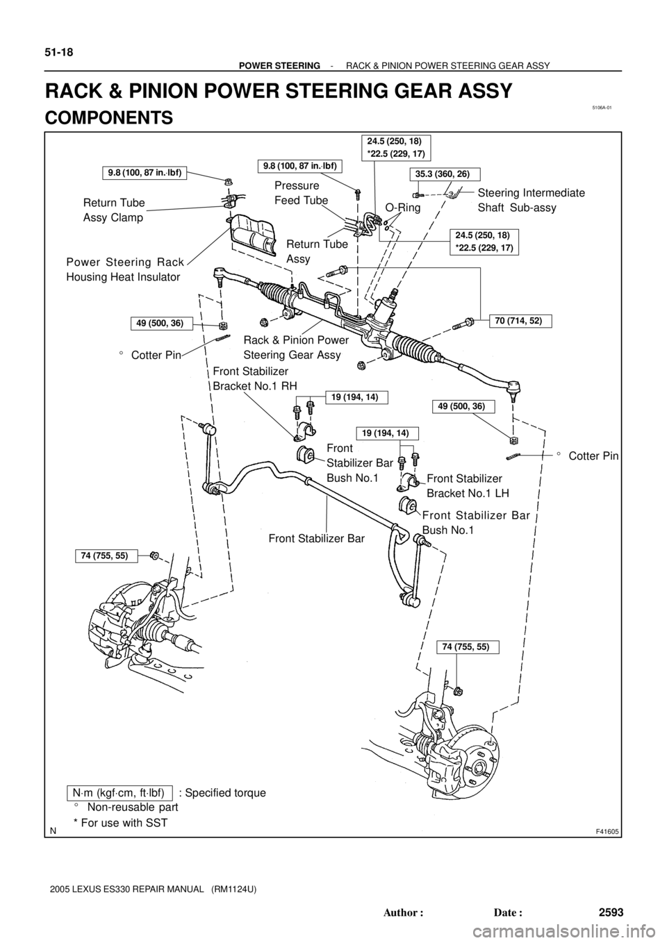
5106A-01
F41605
Rack & Pinion Power
Steering Gear Assy
� Cotter Pin Return Tube
Assy Clamp
Power Steering Rack
Housing Heat InsulatorPressure
Feed Tube
Return Tube
Assy
Front Stabilizer
Bracket No.1 LH Front Stabilizer
Bracket No.1 RH
Front Stabilizer Bar
Front
Stabilizer Bar
Bush No.1
Front Stabilizer Bar
Bush No.1
* For use with SST
NVm (kgfVcm, ftVlbf) : Specified torque
� Non-reusable part
24.5 (250, 18)
*22.5 (229, 17)
19 (194, 14)
� Cotter Pin
O-Ring
9.8 (100, 87 in.Vlbf)9.8 (100, 87 in.Vlbf)
24.5 (250, 18)
*22.5 (229, 17)
35.3 (360, 26)
70 (714, 52)
49 (500, 36)
19 (194, 14)
74 (755, 55)
74 (755, 55)
49 (500, 36)
Steering Intermediate
Shaft Sub-assy
51-18
- POWER STEERINGRACK & PINION POWER STEERING GEAR ASSY
2593 Author�: Date�:
2005 LEXUS ES330 REPAIR MANUAL (RM1124U)
RACK & PINION POWER STEERING GEAR ASSY
COMPONENTS
Page 741 of 969
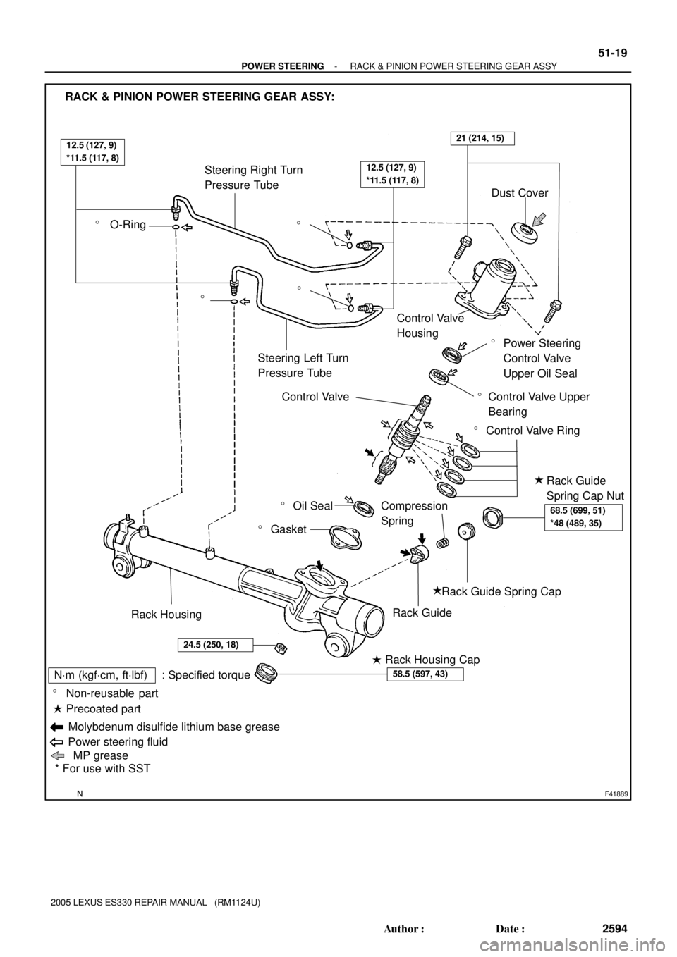
F41889
Rack Housing
� Rack Housing Cap
� Gasket
Control Valve
Steering Right Turn
Pressure Tube
Steering Left Turn
Pressure Tube
�
� O-Ring
�
�
Dust Cover
Control Valve
Housing
� Power Steering
Control Valve
Upper Oil Seal
Control Valve Upper
Bearing�
� Control Valve Ring
Rack Guide
Spring Cap Nut�
Rack Guide Spring Cap
Rack Guide
Compression
Spring
RACK & PINION POWER STEERING GEAR ASSY:
�
* For use with SST � Non-reusable part
NVm (kgfVcm, ftVlbf) : Specified torque
Molybdenum disulfide lithium base grease
� Precoated part
Power steering fluid
MP grease
� Oil Seal
12.5 (127, 9)
*11.5 (117, 8)
12.5 (127, 9)
*11.5 (117, 8)
21 (214, 15)
68.5 (699, 51)
*48 (489, 35)
58.5 (597, 43)
24.5 (250, 18)
- POWER STEERINGRACK & PINION POWER STEERING GEAR ASSY
51-19
2594 Author�: Date�:
2005 LEXUS ES330 REPAIR MANUAL (RM1124U)