Page 364 of 969

30-19
2422 Author�: Date�:
2005 LEXUS ES330 REPAIR MANUAL (RM1124U)
FRONT AXLE HUB SUB-A")
300M6-02
C91612
C83023
F40153
SST
- DRIVE SHAFT / PROPELLER SHAFTFRONT AXLE HUB SUB-ASSY LH (From July, 2003)
30-19
2422 Author�: Date�:
2005 LEXUS ES330 REPAIR MANUAL (RM1124U)
FRONT AXLE HUB SUB-ASSY LH (From July, 2003)
REPLACEMENT
HINT:
�Replace the RH side using the same procedures as for the LH side.
1. REMOVE FRONT WHEEL
2. REMOVE FRONT AXLE HUB LH NUT (SEE PAGE 30-8)
SST 09930-00010
3. DISCONNECT SPEED SENSOR FRONT LH (SEE PAGE 30-8)
4. SEPARATE FRONT DISC BRAKE CALIPER ASSY LH
(a) Remove the 2 bolts and separate the front disc brake cali-
per assy LH from the steering knuckle LH.
NOTICE:
Use a string or other device to keep the brake caliper from
hanging down by the flexible hose.
5. REMOVE FRONT DISC
6. SEPARATE TIE ROD ASSY LH (SEE PAGE 30-8)
SST 09628-6201 1
7. SEPARATE FRONT SUSPENSION ARM SUB-ASSY LOWER NO.1 LH (SEE PAGE 30-8)
8. REMOVE FRONT AXLE ASSY LH
(a) Using a plastic hammer, separate the front drive shaft
assy LH from the front axle hub sub-assy LH.
NOTICE:
Be careful not to damage the boot and speed sensor rotor.
(b) Remove the 2 bolts, nuts and steering knuckle with the
axle hub.
9. REMOVE LOWER BALL JOINT ASSY FRONT LH
(a) Remove the cotter pin and nut.
(b) Using SST, remove the lower ball joint assy front LH.
SST 09628-6201 1
Page 366 of 969

30-21
2424 Author�: Date�:
2005 LEXUS ES330 REPAIR MANUA")
F40230
SST
SST
F11547
SST
Spanner
V Block
F40231
SST
F40157
SST
SST
- DRIVE SHAFT / PROPELLER SHAFTFRONT AXLE HUB SUB-ASSY LH (From July, 2003)
30-21
2424 Author�: Date�:
2005 LEXUS ES330 REPAIR MANUAL (RM1124U)
14. REMOVE FRONT AXLE HUB LH BEARING
(a) Place the bearing inner race (outside) on the front axle
hub LH bearing.
(b) Using SST and a press, press the front axle hub LH bear-
ing until it contacts the SST.
SST 09527- 17011, 09950- 60010 (09951- 00600),
09950-70010 (09951-07100)
(c) Using a spanner to make the steering knuckle LH horizon-
tal, fix it to the V block as shown in the illustration.
NOTICE:
Be sure that the steering knuckle is horizontally posi-
tioned.
(d) Using SST and a press, remove the front axle hub LH
bearing.
SST 09950- 60010 (09951- 00600), 09950- 70010
(09951-07100)
15. INSTALL FRONT AXLE HUB LH BEARING
(a) Using SST and a press, install a new front axle hub LH
bearing to the steering knuckle LH.
SST 09950- 60020 (09951- 00790), 09950- 70010
(09951-07100)
16. INSTALL DISC BRAKE DUST COVER FRONT LH
(a) Place the disc brake dust cover front LH and using a torx wrench (T30), torque the 4 bolts.
Torque: 8.3 NVm (85 kgfVcm, 73 in.Vlbf)
17. INSTALL FRONT AXLE HUB SUB-ASSY LH
(a) Using SST and a press, install the front axle hub sub-
assy LH.
SST 09608- 32010, 09950- 60020 (09951- 00790),
09950-70010 (09951-07100)
Page 367 of 969

2425 Author�: Date�:
2005 LEXUS ES330 REPAIR MANUAL (RM1124U)
18. INSTALL FRONT AXL")
C83852F45465
C97690F45054
C83023
30-22
- DRIVE SHAFT / PROPELLER SHAFTFRONT AXLE HUB SUB-ASSY LH (From July, 2003)
2425 Author�: Date�:
2005 LEXUS ES330 REPAIR MANUAL (RM1124U)
18. INSTALL FRONT AXLE HUB LH HOLE SNAP RING
(a) Using snap ring pliers, install a new front axle hub LH hole
snap ring.
19. INSTALL FRONT WHEEL BEARING DUST
DEFLECTOR NO.1 LH
(a) Using SST and a hammer, install the bearing dust deflec-
tor No.1 LH.
SST 09316- 60011 (09316- 00011, 09316- 00031),
09608-32010
HINT:
Aligh the hole for the speed sensor in the bearing dust deflector
No.1 LH with the steering knuckle.
20. INSTALL LOWER BALL JOINT ASSY FRONT LH
(a) Install the lower ball joint assy front LH and tighten the nut.
Torque: 123 NVm (1,254 kgfVcm, 90 ftVlbf)
(b) Install a new cotter pin.
NOTICE:
If the holes for the cotter pin are not aligned, tighten the nut up to 60� further.
21. INSTALL FRONT AXLE ASSY LH
(a) Install the front axle assy LH with the 2 bolts and nuts to
the shock absorber assy front LH.
Torque: 210 NVm (2,141 kgfVcm, 155 ftVlbf)
NOTICE:
�Only when reusing the bolts and nuts, apply the small
amount of engine oil to the screw part of the nuts.
�Do not excessively push out the front axle assy LH.
�Be careful not to damage the outboard joint boot.
�Be careful not to damage the speed sensor rotor.
22. INSTALL FRONT SUSPENSION ARM SUB-ASSY LOWER NO.1 LH (SEE PAGE 30-8)
23. INSTALL TIE ROD ASSY LH (SEE PAGE 30-8)
24. INSTALL FRONT DISC
Page 368 of 969

30-23
2426 Author�: Date�:
2005 LEXUS ES330 REPAIR MANUAL (RM1124U)
25. INSTALL FRONT DISC BRA")
C91612
C91612
F40163
F40164
- DRIVE SHAFT / PROPELLER SHAFTFRONT AXLE HUB SUB-ASSY LH (From July, 2003)
30-23
2426 Author�: Date�:
2005 LEXUS ES330 REPAIR MANUAL (RM1124U)
25. INSTALL FRONT DISC BRAKE CALIPER ASSY LH
(a) Install the front disc brake caliper assy LH with the 2 bolts
to the steering knuckle LH.
Torque: 107 NVm (1,090 kgfVcm, 79 ftVlbf)
26. INSTALL FRONT AXLE HUB LH NUT (SEE PAGE30-8)
(a) Using a socket wrench (30 mm), install a new axle hub LH nut.
Torque: 294 NVm (2,998 kgfVcm, 217 ftVlbf)
27. DISCONNECT FRONT DISC BRAKE CALIPER ASSY
LH
(a) Remove the 2 bolts and separate the front disc brake cali-
per assy LH from the steering knuckle LH.
NOTICE:
Use a string or other device to keep the brake caliper from
hanging down by the flexible hose.
28. REMOVE FRONT DISC
29. INSPECT BEARING BACKLASH
(a) Using a dial indicator, check the backlash near the center
of the axle hub.
Maximum: 0.05 mm (0.0020 in.)
If the backlash exceeds the maximum, replace the bearing.
30. INSPECT AXLE HUB DEVIATION
(a) Using a dial indicator, check the deviation at the surface
of the axle hub outside the hub bolt.
Maximum: 0.05 mm (0.0020 in.)
If the deviation exceeds the maximum, replace the axle hub.
Page 369 of 969
C91612
C68609
30-24
- DRIVE SHAFT / PROPELLER SHAFTFRONT AXLE HUB SUB-ASSY LH (From July, 2003)
2427 Author�: Date�:
2005 LEXUS ES330 REPAIR MANUAL (RM1124U)
31. INSTALL FRONT DISC
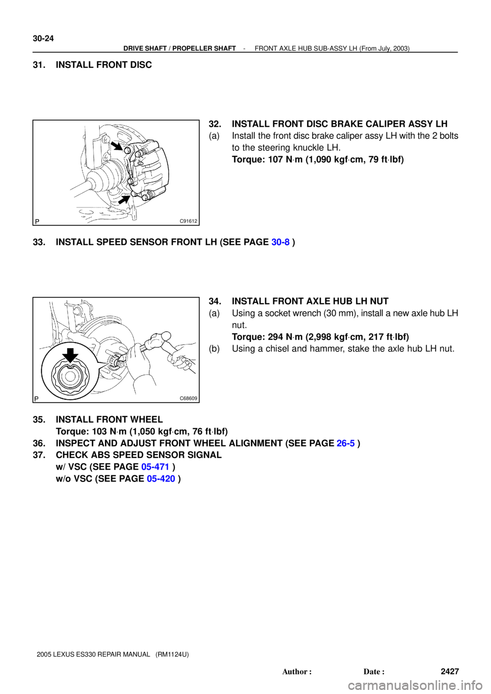
32. INSTALL FRONT DISC BRAKE CALIPER ASSY LH
(a) Install the front disc brake caliper assy LH with the 2 bolts
to the steering knuckle LH.
Torque: 107 NVm (1,090 kgfVcm, 79 ftVlbf)
33. INSTALL SPEED SENSOR FRONT LH (SEE PAGE 30-8)
34. INSTALL FRONT AXLE HUB LH NUT
(a) Using a socket wrench (30 mm), install a new axle hub LH
nut.
Torque: 294 NVm (2,998 kgfVcm, 217 ftVlbf)
(b) Using a chisel and hammer, stake the axle hub LH nut.
35. INSTALL FRONT WHEEL
Torque: 103 NVm (1,050 kgfVcm, 76 ftVlbf)
36. INSPECT AND ADJUST FRONT WHEEL ALIGNMENT (SEE PAGE
26-5)
37. CHECK ABS SPEED SENSOR SIGNAL
w/ VSC (SEE PAGE 05-471)
w/o VSC (SEE PAGE 05-420)
Page 393 of 969
A84925N´m (kgf´cm, ft´lbf)
: Specified torque
58 (591, 43)
28 (286, 21)
8.4 (85, 74 in.Vlbf)
43 (438, 32)
18 (178, 13)
18 (184, 13)
9.8 (100, 7)
64 (653, 47)
64 (653, 47)
23 (235, 17)
25 (250, 18)
V Belt No. 1
Generator Bracket No. 2
Engine Moving
Control Rod
Generator Assy
Generator Belt Adjusting BarEngine Mounting
Stay No. 2 RH
Fuel Vapor
Feed Hose No. 1
Union to Check
Valve Hose
Heater Inlet
Water Hose
Fuel Pipe
Sub-assy No. 1
Fuel Pipe Clamp No. 1
Transmission Control
Cable Assy
Heater Outlet
Water Hose
Radiator Hose Outlet
Steering Gear Outlet
Return Tube
Radiator Hose Inlet
Oil Reservoir to Pump Hose No. 1
Fan Belt Adjusting
Bar Bracket
25 (250, 18)
25 (250, 18)15 (153, 11)
Oil Cooler Inlet Hose
Oil Cooler Outlet Hose
Radio Setting
Condenser
Compressor and
Magnetic Clutch
- ENGINE MECHANICALPARTIAL ENGINE ASSY (3MZ-FE)
14-17
2109 Author�: Date�:
2005 LEXUS ES330 REPAIR MANUAL (RM1124U)
Page 394 of 969
A84926
N´m (kgf´cm, ft´lbf)
: Specified torque
49 (500, 36)
74 (755, 55)
75 (765, 55)
Steering Intermediate Shaft Assy
Front Suspension Arm
Sub-assy Lower No. 1 LH
Front Axle Hub LH Nut
Tie Rod Assy LH
Speed Sensor Front LH
� Cotter Pin
294 (2,998, 217)�
62 (633, 46)
Exhaust Pipe Assy Front
Exhaust Pipe No. 1
Support Bracket Front
8.0 (82, 71 in.Vlbf)
75 (765, 55)
� Exhaust Pipe Gasket
� Non-reusable part33 (337, 24)
35 (360, 26)
Front Stabilizer Link
Assy LH
35 (360, 26)
�
56 (571, 41)
� Exhaust Pipe
Gasket
33 (337, 24)
Exhaust Pipe No. 1
Support Bracket Rear
�
� Exhaust Pipe
Gasket
62 (633, 46)
14-18
- ENGINE MECHANICALPARTIAL ENGINE ASSY (3MZ-FE)
2110 Author�: Date�:
2005 LEXUS ES330 REPAIR MANUAL (RM1124U)
Page 406 of 969

2122 Author�: Date�:
2005 LEXUS ES330 REPAIR MANUAL (RM1124U)
37. DISCONNECT STEERING GEAR OUTLET RETURN
TUBE
38. REMOVE GLOVE COM")
A60073
A59893
14-30
- ENGINE MECHANICALPARTIAL ENGINE ASSY (3MZ-FE)
2122 Author�: Date�:
2005 LEXUS ES330 REPAIR MANUAL (RM1124U)
37. DISCONNECT STEERING GEAR OUTLET RETURN
TUBE
38. REMOVE GLOVE COMPARTMENT DOOR ASSY (See page 10-22)
39. SEPARATE ENGINE WIRE
(a) Disconnect the engine wire harness from the ECM and
junction block.
(b) Disconnect the engine wire harness from the engine room
junction block.
(1) Remove the nut, then separate the engine wire har-
ness.
(2) Using a screwdriver, release the engine room junc-
tion block. Separate the engine wire harness by
pulling it upward.
(c) Remove the 2 nuts, then pull out the engine wire harness.
(d) Remove the body ground.
40. REMOVE EXHAUST PIPE NO.1 SUPPORT BRACKET FRONT (See page 15-2)
41. REMOVE EXHAUST PIPE NO.1 SUPPORT BRACKET REAR (See page 15-2)
42. REMOVE EXHAUST PIPE ASSY FRONT (See page 15-2)
43. DISCONNECT FRONT STABILIZER LINK ASSY LH (See page 30-8)
44. DISCONNECT FRONT STABILIZER LINK ASSY RH
HINT:
Perform the same procedure as above on the opposite side.
45. REMOVE FRONT AXLE HUB LH NUT (See page 30-8)
SST 09930-00010
46. REMOVE FRONT AXLE HUB RH NUT
SST 09930-00010
HINT:
Perform the same procedure as above on the opposite side.
47. SEPARATE SPEED SENSOR FRONT LH (See page 30-8)
48. SEPARATE SPEED SENSOR FRONT RH
HINT:
Perform the same procedure as above on the opposite side.
49. SEPARATE TIE ROD ASSY LH (See page 30-8)
SST 09628-6201 1
50. SEPARATE TIE ROD ASSY RH
SST 09628-6201 1
HINT:
Perform the same procedure as above on the opposite side.

: Specified torque
58 (591, 43)
28 (286, 21)
8.4 (85, 74 in.Vlbf)
43 (438, 32)
18 (178, 13)
18 (184, 13)
9.8 (100, 7)
64 (653, 47)
64 (653, 47)
23 (235, 17)
25 (250, 18)")

: Specified torque
49 (500, 36)
74 (755, 55)
75 (765, 55)
Steering Intermediate Shaft Assy
Front Suspension Arm
Sub-assy Lower No. 1 LH
Front Axle Hub LH Nut
Tie Rod A")