Page 731 of 969

OVERHAUL
NOTICE:
�When using a vise, do not over tighten.
�When installing, c")
51069-02
F41598
F41599
- POWER STEERINGVANE PUMP ASSY
51-9
2584 Author�: Date�:
2005 LEXUS ES330 REPAIR MANUAL (RM1124U)
OVERHAUL
NOTICE:
�When using a vise, do not over tighten.
�When installing, coat the parts indicated by the arrows with power steering fluid
(See page 51-7).
1. REMOVE FRONT WHEEL RH
2. DRAIN POWER STEERING FLUID
3. REMOVE FRONT FENDER LINER RH
4. REMOVE FRONT FENDER APRON SEAL RH
5. DISCONNECT OIL RESERVOIR TO PUMP HOSE NO.1
(a) Remove the clip and disconnect the oil reservoir to pump hose No.1.
NOTICE:
Take care not to spill fluid on the V belt.
6. REMOVE POWER STEERING OIL PRESSURE SWITCH
(a) Disconnect the connector.
(b) Remove the oil power steering pressure switch from the union bolt.
NOTICE:
Be careful not to drop the oil power steering pressure switch.
If the oil power steering pressure switch is dropped or strongly damaged, replace it with a new one.
7. DISCONNECT PRESSURE FEED HOSE
(a) Using a spanner (22 mm) to hold the pressure port union,
remove the union bolt and gasket.
8. REMOVE VANE PUMP V BELT
(a) Loosen the 2 bolts and remove the vane pump V belt.
9. REMOVE VANE PUMP ASSY
(a) Remove the 2 bolts and vane pump assy.
Page 766 of 969

SHOCK ABSORBER ASSY REAR LH
REPLACEMENT
HINT:
COMPONENTS: See p")
2706G-03
C66631
F41030
27-4
- REAR SUSPENSIONSHOCK ABSORBER ASSY REAR LH
2386 Author�: Date�:
2005 LEXUS ES330 REPAIR MANUAL (RM1124U)
SHOCK ABSORBER ASSY REAR LH
REPLACEMENT
HINT:
COMPONENTS: See page 27-2
1. REMOVE REAR WHEEL
2. REMOVE REAR SEAT CUSHION ASSY (See page 72-39)
3. REMOVE REAR SEATBACK ASSY (See page 72-39)
4. REMOVE ROOF SIDE GARNISH INNER RH (See page 76-25)
5. REMOVE ROOF SIDE GARNISH INNER LH
HINT:
Remove the LH side by the same procedures with the RH side.
6. REMOVE REAR DOOR OPENING TRIM WEATHERSTRIP RH (See page 72-39)
7. REMOVE REAR DOOR OPENING TRIM WEATHERSTRIP LH
HINT:
Remove the LH side by the same procedures with the RH side.
8. REMOVE CENTER STOP LAMP ASSY (W/O SUN SHADE) (See page 65-31)
9. REMOVE REAR SEAT SHOULDER BELT COVER (See page 61-15)
10. REMOVE PACKAGE TRAY TRIM PANEL ASSY (W/ SUN SHADE) (See page 61-15)
11. REMOVE PACKAGE TRAY TRIM PANEL ASSY (W/O SUN SHADE) (See page 61-15)
12. REMOVE REAR SEAT 3 POINT TYPE BELT ASSY OUTER (See page 61-15)
13. SEPARATE REAR STABILIZER LINK ASSY LH
(a) Remove the nut and disconnect the stabilizer bar link from
the shock absorber.
HINT:
If the ball joint turns together with the nut, use a hexagon (5 mm)
wrench to hold the stud.
14. REMOVE REAR SUSPENSION SUPOPORT NO.1 COVER LH (W/O H-TEMS SUSPENSION)
15. REMOVE REAR SHOCK ABSORBER WITH COIL
SPRING
(a) Remove the 2 bolts, disconnect the flexible hose and ABS
speed sensor wire harness from shock absorber.
Page 778 of 969
2701O-06
C91816
C66721
27-16
- REAR SUSPENSIONSTABILIZER BAR REAR
2398 Author�: Date�:
2005 LEXUS ES330 REPAIR MANUAL (RM1124U)
STABILIZER BAR REAR
REPLACEMENT
HINT:
COMPONENTS: See page 27-2
1. REMOVE REAR WHEEL
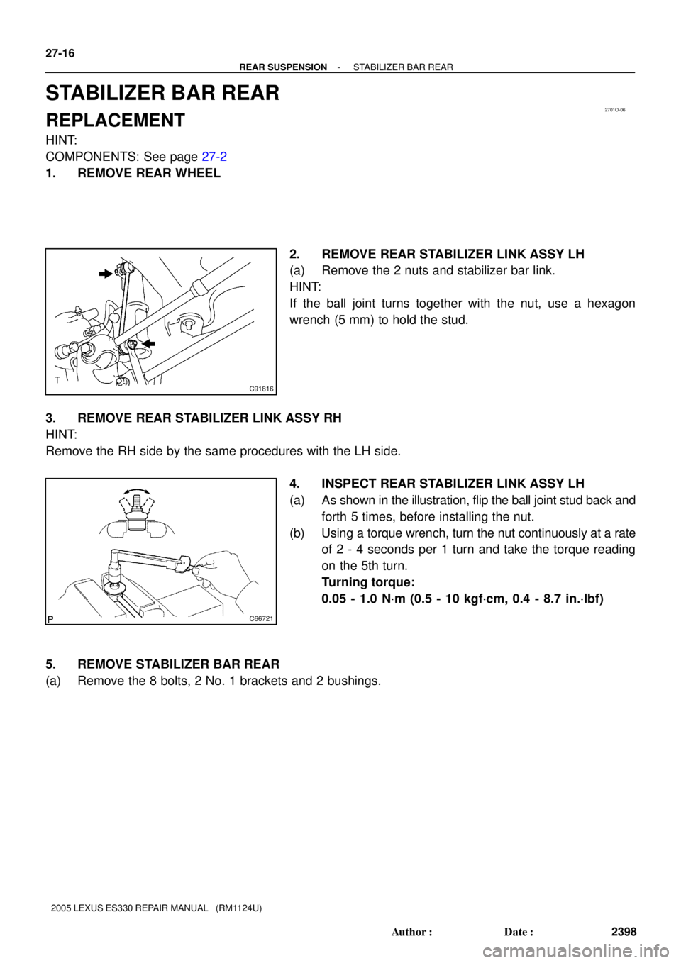
2. REMOVE REAR STABILIZER LINK ASSY LH
(a) Remove the 2 nuts and stabilizer bar link.
HINT:
If the ball joint turns together with the nut, use a hexagon
wrench (5 mm) to hold the stud.
3. REMOVE REAR STABILIZER LINK ASSY RH
HINT:
Remove the RH side by the same procedures with the LH side.
4. INSPECT REAR STABILIZER LINK ASSY LH
(a) As shown in the illustration, flip the ball joint stud back and
forth 5 times, before installing the nut.
(b) Using a torque wrench, turn the nut continuously at a rate
of 2 - 4 seconds per 1 turn and take the torque reading
on the 5th turn.
Turning torque:
0.05 - 1.0 N´m (0.5 - 10 kgf´cm, 0.4 - 8.7 in.´lbf)
5. REMOVE STABILIZER BAR REAR
(a) Remove the 8 bolts, 2 No. 1 brackets and 2 bushings.
Page 779 of 969
C93541
A
B
B53738
C91816
- REAR SUSPENSIONSTABILIZER BAR REAR
27-17
2399 Author�: Date�:
2005 LEXUS ES330 REPAIR MANUAL (RM1124U)
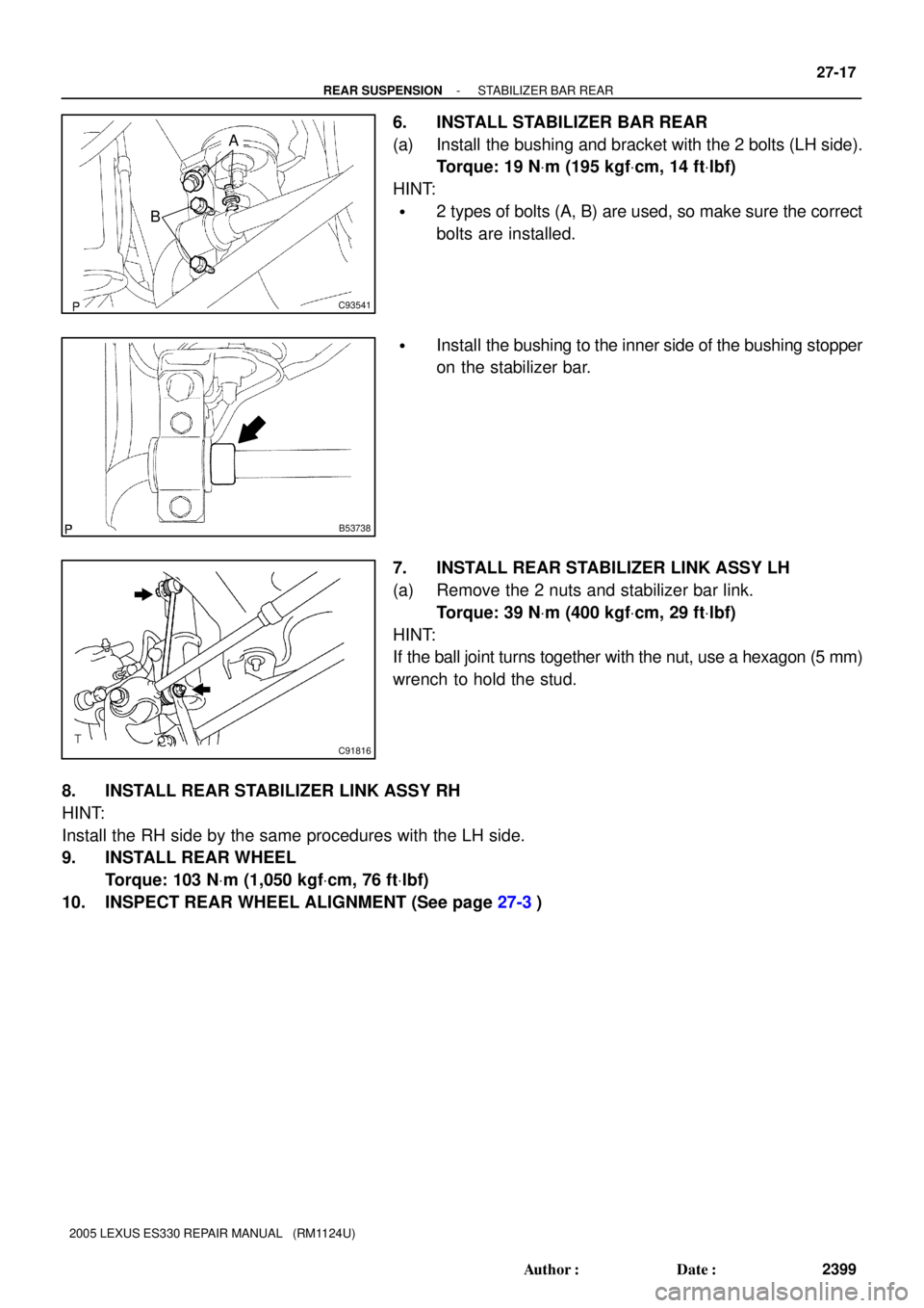
6. INSTALL STABILIZER BAR REAR
(a) Install the bushing and bracket with the 2 bolts (LH side).
Torque: 19 NVm (195 kgfVcm, 14 ftVlbf)
HINT:
�2 types of bolts (A, B) are used, so make sure the correct
bolts are installed.
�Install the bushing to the inner side of the bushing stopper
on the stabilizer bar.
7. INSTALL REAR STABILIZER LINK ASSY LH
(a) Remove the 2 nuts and stabilizer bar link.
Torque: 39 NVm (400 kgfVcm, 29 ftVlbf)
HINT:
If the ball joint turns together with the nut, use a hexagon (5 mm)
wrench to hold the stud.
8. INSTALL REAR STABILIZER LINK ASSY RH
HINT:
Install the RH side by the same procedures with the LH side.
9. INSTALL REAR WHEEL
Torque: 103 NVm (1,050 kgfVcm, 76 ftVlbf)
10. INSPECT REAR WHEEL ALIGNMENT (See page 27-3)
Page 958 of 969
REPAIR MANUAL SUPPLEMENT: VEHICLE PULLING TO ONE SIDE ± ST004-01 RevisedDecember 21, 2001
Page 11 of 11
G. Install the front wheels.
Torque: 103 N�m (1,050 kgf�cm, 76 ft�lbf)
H. Check the camber.
NOTE:
Adjusting value for the set bolts
is
6' ± 30' (0.1� ± 0.5�).
When making an adjustment of more
than 45', replace the upper and lower
steering knuckle set bolts with the
adjusting bolts
. If the camber is not
within the specification, use the table
shown to estimate how much
additional camber adjustment will be
required, and select the appropriate
camber adjusting bolt.
I. Follow steps 5±a through 5±h
again. Between steps 5±b and
5±c, exchange one or two
selected bolts.
HINT:
When exchanging the two bolts,
exchange one bolt each time.
If Vehicle Pull Is Eliminated: Repair Is Now Complete.
If Vehicle Is Still Pulling: Contact Your Regional Office For Further Assistance.
Repair
Procedures
(Continued)

H. Check the camber.
NOT")