Page 365 of 969
F40154
C83852F45465
F40156
SST
F02261
SST
30-20
- DRIVE SHAFT / PROPELLER SHAFTFRONT AXLE HUB SUB-ASSY LH (From July, 2003)
2423 Author�: Date�:
2005 LEXUS ES330 REPAIR MANUAL (RM1124U)
10. REMOVE FRONT WHEEL BEARING DUST
DEFLECTOR NO.1 LH
(a) Using a screwdriver, remove the bearing dust deflector
No.1 LH.
11. REMOVE FRONT AXLE HUB LH HOLE SNAP RING
(a) Using a snap ring expander, remove the front axle hub LH
hole snap ring.
12. REMOVE FRONT AXLE HUB SUB-ASSY LH
(a) Using SST, remove the front axle hub sub-assy LH.
SST 09520-00031
(b) Using SST and a press, remove the bearing inner race
(outside) from the front axle hub sub-assy LH.
SST 09950- 00020, 09950- 60010 (09951- 00410),
09950-70010 (09951-07100)
13. REMOVE DISC BRAKE DUST COVER FRONT LH
(a) Using a torx) wrench (T30), remove the 4 bolts and disc brake dust cover front LH.
Page 367 of 969

2425 Author�: Date�:
2005 LEXUS ES330 REPAIR MANUAL (RM1124U)
18. INSTALL FRONT AXL")
C83852F45465
C97690F45054
C83023
30-22
- DRIVE SHAFT / PROPELLER SHAFTFRONT AXLE HUB SUB-ASSY LH (From July, 2003)
2425 Author�: Date�:
2005 LEXUS ES330 REPAIR MANUAL (RM1124U)
18. INSTALL FRONT AXLE HUB LH HOLE SNAP RING
(a) Using snap ring pliers, install a new front axle hub LH hole
snap ring.
19. INSTALL FRONT WHEEL BEARING DUST
DEFLECTOR NO.1 LH
(a) Using SST and a hammer, install the bearing dust deflec-
tor No.1 LH.
SST 09316- 60011 (09316- 00011, 09316- 00031),
09608-32010
HINT:
Aligh the hole for the speed sensor in the bearing dust deflector
No.1 LH with the steering knuckle.
20. INSTALL LOWER BALL JOINT ASSY FRONT LH
(a) Install the lower ball joint assy front LH and tighten the nut.
Torque: 123 NVm (1,254 kgfVcm, 90 ftVlbf)
(b) Install a new cotter pin.
NOTICE:
If the holes for the cotter pin are not aligned, tighten the nut up to 60� further.
21. INSTALL FRONT AXLE ASSY LH
(a) Install the front axle assy LH with the 2 bolts and nuts to
the shock absorber assy front LH.
Torque: 210 NVm (2,141 kgfVcm, 155 ftVlbf)
NOTICE:
�Only when reusing the bolts and nuts, apply the small
amount of engine oil to the screw part of the nuts.
�Do not excessively push out the front axle assy LH.
�Be careful not to damage the outboard joint boot.
�Be careful not to damage the speed sensor rotor.
22. INSTALL FRONT SUSPENSION ARM SUB-ASSY LOWER NO.1 LH (SEE PAGE 30-8)
23. INSTALL TIE ROD ASSY LH (SEE PAGE 30-8)
24. INSTALL FRONT DISC
Page 369 of 969
C91612
C68609
30-24
- DRIVE SHAFT / PROPELLER SHAFTFRONT AXLE HUB SUB-ASSY LH (From July, 2003)
2427 Author�: Date�:
2005 LEXUS ES330 REPAIR MANUAL (RM1124U)
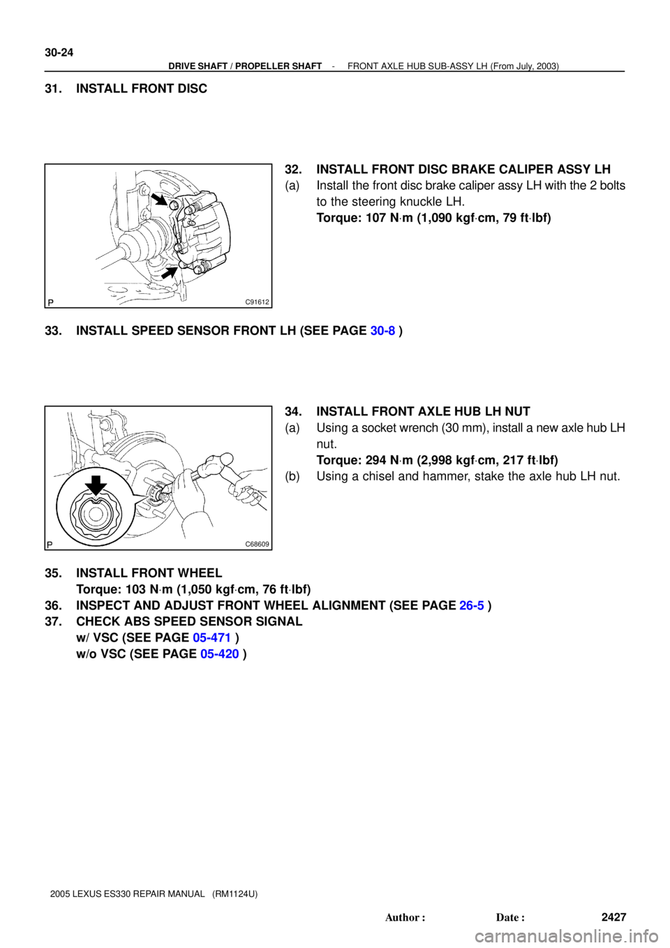
31. INSTALL FRONT DISC
32. INSTALL FRONT DISC BRAKE CALIPER ASSY LH
(a) Install the front disc brake caliper assy LH with the 2 bolts
to the steering knuckle LH.
Torque: 107 NVm (1,090 kgfVcm, 79 ftVlbf)
33. INSTALL SPEED SENSOR FRONT LH (SEE PAGE 30-8)
34. INSTALL FRONT AXLE HUB LH NUT
(a) Using a socket wrench (30 mm), install a new axle hub LH
nut.
Torque: 294 NVm (2,998 kgfVcm, 217 ftVlbf)
(b) Using a chisel and hammer, stake the axle hub LH nut.
35. INSTALL FRONT WHEEL
Torque: 103 NVm (1,050 kgfVcm, 76 ftVlbf)
36. INSPECT AND ADJUST FRONT WHEEL ALIGNMENT (SEE PAGE
26-5)
37. CHECK ABS SPEED SENSOR SIGNAL
w/ VSC (SEE PAGE 05-471)
w/o VSC (SEE PAGE 05-420)
Page 371 of 969
3006I-04
C83014
C83008
C83035
30-26
- DRIVE SHAFT / PROPELLER SHAFTREAR AXLE HUB & BEARING ASSY LH
2429 Author�: Date�:
2005 LEXUS ES330 REPAIR MANUAL (RM1124U)
REAR AXLE HUB & BEARING ASSY LH
REPLACEMENT
HINT:
�COMPONENTS: See page 30-4
�Replace the RH side by the same procedures with the LH side.
1. REMOVE REAR WHEEL
2. DISCONNECT REAR DISC BRAKE CALIPER ASSY LH
(a) Remove the bolt and disconnect the rear flexible hose.
(b) Remove the 2 bolts and rear disc brake caliper assy LH.
(c) Support the rear disc brake caliper assy LH securely.
3. REMOVE REAR DISC
4. DISCONNECT SKID CONTROL SENSOR WIRE
5. REMOVE REAR AXLE HUB & BEARING ASSY LH
(a) Remove the 4 bolts and rear axle hub & bearing assy LH.
6. REMOVE SKID CONTROL SENSOR (SEE PAGE 32-56)
7. INSTALL SKID CONTROL SENSOR (SEE PAGE 32-56)
Page 374 of 969

REAR AXLE CARRIER SUB-ASSY LH
REPLACEME")
3006J-06
C83017
C83018
C83019
- DRIVE SHAFT / PROPELLER SHAFTREAR AXLE CARRIER SUB-ASSY LH
30-29
2432 Author�: Date�:
2005 LEXUS ES330 REPAIR MANUAL (RM1124U)
REAR AXLE CARRIER SUB-ASSY LH
REPLACEMENT
HINT:
�COMPONENTS: See page 30-4
�Replace the RH side by the same procedures with the LH side.
1. REMOVE REAR WHEEL
2. REMOVE STRUT ROD ASSY REAR (SEE PAGE 27-18)
3. DISCONNECT REAR DISC BRAKE CALIPER ASSY LH (SEE PAGE 30-26)
4. REMOVE REAR DISC
5. DISCONNECT SKID CONTROL SENSOR WIRE
6. REMOVE REAR AXLE HUB & BEARING ASSY LH (SEE PAGE 30-26)
7. SEPARATE REAR SUSPENSION ARM ASSY NO.2 LH
(a) Remove the bolt, nut and rear suspension arm assy No.2
LH from the rear axle carrier sub-assy LH.
HINT:
While fixing the nut, turn and remove the bolt.
8. SEPARATE REAR SUSPENSION ARM ASSY NO.1 LH
(a) Remove the bolt, nut and rear suspension arm assy No.1
LH from the rear axle carrier sub-assy LH.
HINT:
While fixing the nut, turn and remove the bolt.
9. REMOVE REAR AXLE CARRIER SUB-ASSY LH
(a) Remove the 2 bolts, nuts and rear axle carrier sub-assy
LH from the shock absorber assy rear LH.
NOTICE:
When removing bolt, stop the bolt from rotating and loosen
the nut.
Page 375 of 969

10. INSTALL REAR AXLE CARRIER SUB-ASSY LH
(a) In")
C83019
C83018
C83017
30-30
- DRIVE SHAFT / PROPELLER SHAFTREAR AXLE CARRIER SUB-ASSY LH
2433 Author�: Date�:
2005 LEXUS ES330 REPAIR MANUAL (RM1124U)
10. INSTALL REAR AXLE CARRIER SUB-ASSY LH
(a) Install the rear axle carrier sub-assy LH with the 2 bolts
and nuts.
Torque: 255 NVm (2,600 kgfVcm, 188 ftVlbf)
NOTICE:
When installing bolt, stop the bolt from rotating and torque
the nut.
HINT:
Insert the bolt from the rear side of the vehicle and install the
nut.
11. TEMPORARILY TIGHTEN REAR SUSPENSION ARM
ASSY NO.1 LH
(a) Install the rear suspension arm assy No.1 LH to the rear
axle carrier sub-assy LH with the bolt and nut, temporarily
tighten the bolt.
HINT:
Insert the bolt from the front side of the vehicle and while fixing
the nut, turn and install the bolt.
12. TEMPORARILY TIGHTEN REAR SUSPENSION ARM
ASSY NO.2 LH
(a) Install the rear suspension arm No.2 to the rear axle carri-
er sub-assy LH with the bolt and nut, temporarily tighten
the bolt.
HINT:
Insert the bolt from the rear side of the vehicle and while fixing
the nut, turn and install the bolt.
13. INSTALL REAR AXLE HUB & BEARING ASSY LH (SEE PAGE 30-26)
14. INSTALL SKID CONTROL SENSOR WIRE
15. INSTALL REAR DISC
16. INSTALL REAR DISC BRAKE CALIPER ASSY LH (SEE PAGE 30-26)
17. TEMPORARILY TIGHTEN STRUT ROD ASSY REAR (SEE PAGE 27-18)
18. STABILIZE SUSPENSION (SEE PAGE 27-18)
19. FULLY TIGHTEN REAR SUSPENSION ARM ASSY NO.1 LH (SEE PAGE 27-10)
20. FULLY TIGHTEN REAR SUSPENSION ARM ASSY NO.2 LH (SEE PAGE 27-14)
21. FULLY TIGHTEN STRUT ROD ASSY REAR (SEE PAGE 27-18)
22. INSTALL REAR WHEEL
Torque: 103 NVm (1,050 kgfVcm, 76 ftVlbf)
23. INSPECT AND ADJUST REAR WHEEL ALIGNMENT (SEE PAGE 27-3)
24. CHECK ABS SPEED SENSOR SIGNAL
w/ VSC (SEE PAGE 05-471)
w/o VSC (SEE PAGE 05-420)
Page 381 of 969

14-5
2097 Author�: Date�:
2005 LEXUS ES330 REPAIR MANUAL (RM1124U)
DRIVE BELT (3MZ-FE)
REPLACEMENT
1. RE")
14193-03
A78698
B
AC
A78699
A
B
A78699
A
B
A78698
B
AC
- ENGINE MECHANICALDRIVE BELT (3MZ-FE)
14-5
2097 Author�: Date�:
2005 LEXUS ES330 REPAIR MANUAL (RM1124U)
DRIVE BELT (3MZ-FE)
REPLACEMENT
1. REMOVE FRONT WHEEL RH
2. REMOVE FRONT FENDER APRON SEAL RH
3. REMOVE V (COOLER COMPRESSOR TO
CRANKSHAFT PULLEY) BELT NO.1
(a) Loosen bolts A and B.
(b) Loosen the adjusting bolt C, then remove the V-ribbed
belt.
4. REMOVE VANE PUMP V BELT
(a) Loosen bolts A and B, then remove the V-ribbed belt.
5. INSTALL VANE PUMP V BELT
(a) Install the V-ribbed belt on each pulley.
(b) Using a bar, adjust the V-ribbed belt tension, then tighten
bolt B.
Torque: 43 NVm (439 kgfVcm, 32 ftVlbf)
(c) Tighten bolt A.
Torque: 43 NVm (439 kgfVcm, 32 ftVlbf)
6. INSTALL V (COOLER COMPRESSOR TO
CRANKSHAFT PULLEY) BELT NO.1
(a) Install the V-ribbed belt on each pulley.
(b) Tighten the adjusting bolt C, then adjust the V-ribbed belt
tension.
(c) First tighten bolt A, then tighten bolt B.
Torque:
18 NVm (178 kgfVcm, 13 ftVlbf) for bolt A
58 NVm (591 kgfVcm, 43 ftVlbf) for bolt B
Page 455 of 969
141JB-01
A78546
A52344
P18816
A78755
SST
- ENGINE MECHANICALTIMING BELT (3MZ-FE)
14-79
2171 Author�: Date�:
2005 LEXUS ES330 REPAIR MANUAL (RM1124U)
REPLACEMENT
1. REMOVE FRONT WHEEL RH
2. REMOVE FRONT FENDER APRON SEAL RH
3. REMOVE V (COOLER COMPRESSOR TO CRANKSHAFT PULLEY) BELT NO.1
(See page 14-5)
4. REMOVE VANE PUMP V BELT (See page 14-5)
5. REMOVE ENGINE MOVING CONTROL ROD
(a) Remove the reserve tank cap.
(b) Remove the 4 bolts, engine moving control rod and brack-
et.
6. REMOVE ENGINE MOUNTING STAY NO.2 RH
(a) Remove the bolt, engine mounting stay No. 2 and engine
mounting bracket No. 2.
7. REMOVE GENERATOR BRACKET NO.2
(a) Remove the nut and generator bracket.
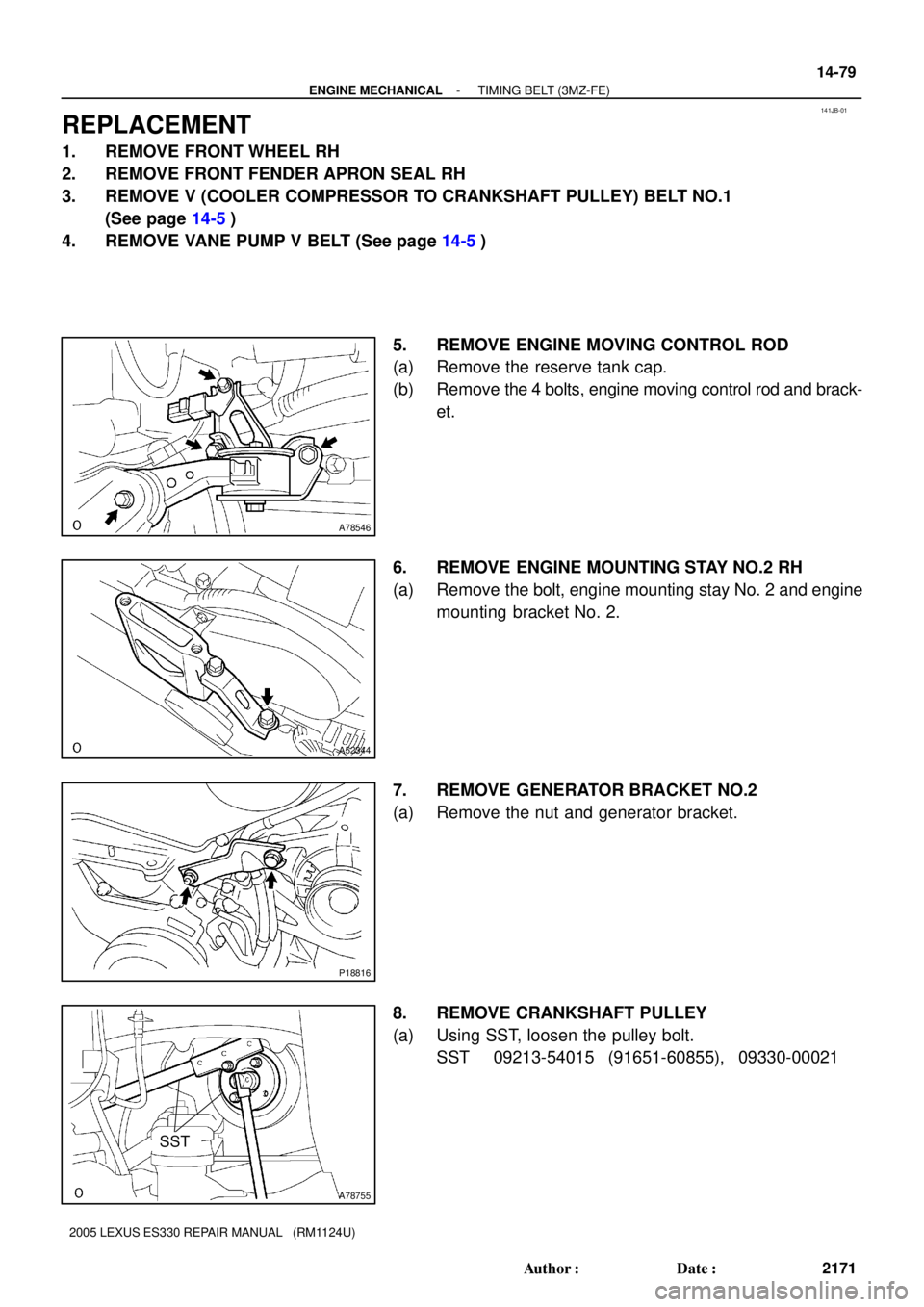
8. REMOVE CRANKSHAFT PULLEY
(a) Using SST, loosen the pulley bolt.
SST 09213-54015 (91651-60855), 09330-00021