Page 336 of 969
33-10
- PARKING BRAKEPARKING BRAKE CABLE ASSY NO.1
2506 Author�: Date�:
2005 LEXUS ES330 REPAIR MANUAL (RM1124U)
18. INSTALL YAWRATE SENSOR (W/ VSC)(See page 32-59)
19. INSTALL CONSOLE BOX DUCT NO.1
20. INSTALL AIR DUCT REAR NO.2
21. INSTALL AIR DUCT REAR NO.1
22. INSTALL INSTRUMENT PANEL FINISH PANEL END LH
23. INSTALL INSTRUMENT PANEL FINISH PANEL END RH
24. INSTALL RR CONSOLE BOX
25. INSTALL CONSOLE BOX CARPET
26. INSTALL CONSOLE PANEL UPPER REAR
27. INSTALL INSTRUMENT PANEL SUB-ASSY LOWER
28. INSTALL INSTRUMENT PANEL UNDER COVER SUB-ASSY NO.1
29. INSTALL INSTRUMENT PANEL INSERT SUB-ASSY LOWER LH
30. INSTALL INSTRUMENT PANEL SUB-ASSY UPPER
31. INSTALL FRONT DOOR SCUFF PLATE LH
32. INSTALL FRONT DOOR SCUFF PLATE RH
33. INSPECT AND ADJUST PARKING BRAKE PEDAL TRAVEL(See page 33-2)
34. CHECK VSC SENSOR SIGNAL (W/ VSC)(See page 05-471)
Page 579 of 969
100J9-02
A86255
(a)
(b)
(a)
(b)(a)
A86256
(b)
(a)
(b)
(b)
(b)
(b)
(c)
(c)
A86257
(a)
(a)
A86258
(a)
(a) 10-22
- ENGINE CONTROL SYSTEMECM (3MZ-FE)
2027 Author�: Date�:
2005 LEXUS ES330 REPAIR MANUAL (RM1124U)
ECM (3MZ-FE)
REPLACEMENT
1. DISCONNECT ENGINE WIRE NO. 3 (BATTERY NEGATIVE TERMINAL)
2. REMOVE FRONT DOOR SCUFF PLATE RH (See page 71-1 1)
3. REMOVE INSTRUMENT PANEL UNDER COVER SUB-ASSY NO.1 (See page 71-1 1)
4. REMOVE INSTRUMENT PANEL SUB-ASSY LOWER (See page 71-1 1)
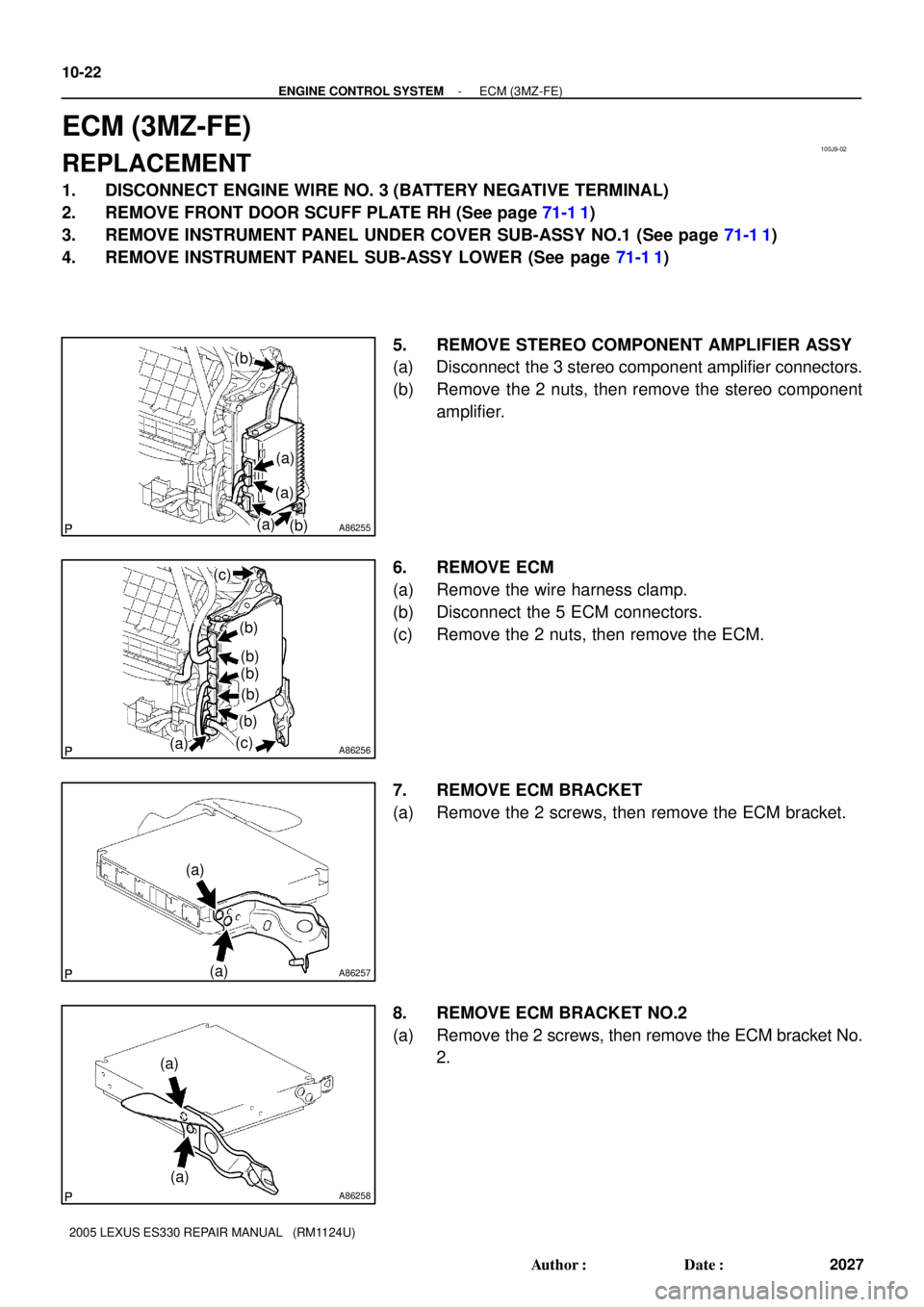
5. REMOVE STEREO COMPONENT AMPLIFIER ASSY
(a) Disconnect the 3 stereo component amplifier connectors.
(b) Remove the 2 nuts, then remove the stereo component
amplifier.
6. REMOVE ECM
(a) Remove the wire harness clamp.
(b) Disconnect the 5 ECM connectors.
(c) Remove the 2 nuts, then remove the ECM.
7. REMOVE ECM BRACKET
(a) Remove the 2 screws, then remove the ECM bracket.
8. REMOVE ECM BRACKET NO.2
(a) Remove the 2 screws, then remove the ECM bracket No.
2.
Page 580 of 969
A86259
(a)
(a)
- ENGINE CONTROL SYSTEMECM (3MZ-FE)
10-23
2028 Author�: Date�:
2005 LEXUS ES330 REPAIR MANUAL (RM1124U)
9. REMOVE ECM BRACKET NO.3
(a) Remove the 2 screws, then remove the ECM bracket No
3.
10. INSTALL ECM BRACKET NO.3
11. INSTALL ECM BRACKET NO.2
12. INSTALL ECM BRACKET
13. INSTALL ECM
Torque: 5.5 NVm (56 kgfVcm, 49 in.Vlbf)
14. INSTALL STEREO COMPONENT AMPLIFIER ASSY
Torque: 5.5 NVm (56 kgfVcm, 49 in.Vlbf)
15. INSTALL INSTRUMENT PANEL SUB-ASSY LOWER
16. INSTALL INSTRUMENT PANEL UNDER COVER SUB-ASSY NO.1
17. INSTALL FRONT DOOR SCUFF PLATE RH
18. CONNECT ENGINE WIRE NO. 3 (BATTERY NEGATIVE TERMINAL)
Torque: 5.4 NVm (55 kgfVcm, 48 in.Vlbf)
19. RESET MEMORY (See page 05-604)
20. SYSTEM INITIALIZATION (See page 19-15)
Page 815 of 969
5002H-02
C90698
Steering Column
CoverHorn Button Assy
Steering Wheel Assy
Steering Pad SwitchConnector
Cover
Turn Signal Switch Assy
50 (510, 37)
Steering Column Cover
Lower No.2Instrument Panel
Finish Plate
NVm (kgfVcm, ftVlbf) : Specified torque
21 (214, 15)
8.8 (90, 78 in.Vlbf)
Steering Wheel
Cover Lower No. 2
Instrument Panel Sub-assy Upper
Steering Column Assy
Steering Column Hole
Cover Sub-assy No. 2
Hose Clamp
Heater to Foot
Duct No. 3
Steering Intermediate
Shaft Sub-assyInstrument Panel Insert
Sub-assy Lower LH
Front Door Scuff Plate LH
35 (360, 26)
35 (360, 26)
21 (214, 15)
50-6
- STEERING COLUMNSTEERING COLUMN ASSY
2567 Author�: Date�:
2005 LEXUS ES330 REPAIR MANUAL (RM1124U)
STEERING COLUMN ASSY
COMPONENTS
Page 817 of 969

2. DISCONNECT BATTERY NEGATIVE TERMINAL(See page 60-1")
5002I-04
C90684
Matchmarks
SST
C90685
C90686
50-8
- STEERING COLUMNSTEERING COLUMN ASSY
2569 Author�: Date�:
OVERHAUL
1. PRECAUTION(See page 60-1)
2. DISCONNECT BATTERY NEGATIVE TERMINAL(See page 60-1)
3. PLACE FRONT WHEELS FACING STRAIGHT AHEAD
4. REMOVE STEERING WHEEL COVER LOWER NO.2
5. REMOVE CONNECTOR COVER
6. REMOVE STEERING PAD SWITCH
(a) Remove the 2 screws.
(b) Disconnect the connector and remove the steering pad switch.
7. REMOVE HORN BUTTON ASSY(See page 60-22)
8. REMOVE STEERING WHEEL ASSY
(a) Remove the steering wheel assy set nut.
(b) Place matchmarks on the steering wheel assy and steer-
ing main shaft assy.
(c) Using SST, remove the steering wheel assy.
SST 09950- 50013 (09951- 05010, 09952- 05010,
09953-05020, 09954-05021)
9. REMOVE FRONT DOOR SCUFF PLATE LH(See page 71-1 1)
10. REMOVE INSTRUMENT PANEL SUB-ASSY UPPER(See page 71-1 1)
11. REMOVE INSTRUMENT PANEL INSERT SUB-ASSY LOWER LH(See page 71-1 1)
12. REMOVE HEATER TO FOOT DUCT NO.3(See page 71-1 1)
13. REMOVE STEERING COLUMN COVER LWR NO.2
(a) Remove the steering column cover lwr No.2.
14. REMOVE STEERING COLUMN COVER
(a) Remove the 3 screws and steering column cover.
Page 818 of 969
 Disconnect the 3 connectors.
(b) Disconnect the airbag connector.
(c) Rem")
C90687
C90688Matchmarks
- STEERING COLUMNSTEERING COLUMN ASSY
50-9
2570 Author�: Date�:
15. REMOVE TURN SIGNAL SWITCH ASSY
(a) Disconnect the 3 connectors.
(b) Disconnect the airbag connector.
(c) Remove the 3 screws and turn signal switch assy.
16. REMOVE INSTRUMENT PANEL FINISH PLATE(See page 71-1 1)
17. DISCONNECT FLOOR SHIFT PARKING LOCK CABLE
ASSY
(a) Place the ignition switch lock cylinder assy at the key ACC
position.
(b) Remove the cable cap claw from the key interlock and pull
out the floor shift parking lock cable assy.
18. DISCONNECT STEERING SLIDING YOKE SUB-ASSY
(a) Place the matchmarks on the steering sliding yoke sub-
assy and intermediate shaft sub-assy.
(b) Remove the bolt and disconnect the steering sliding yoke
sub-assy .
19. REMOVE STEERING COLUMN HOLE COVER SUB-ASSY NO.2
(a) Remove the hose clamp.
(b) Remove the steering column hole cover sub-assy No.2.
20. REMOVE STEERING COLUMN ASSY
(a) Disconnect the connectors and wire harness clamps.
(b) Disconnect the driver side junction block.
Page 819 of 969
C90690
C90689
Matchmarks
C90844H41505
Matchmarks
C90692
50-10
- STEERING COLUMNSTEERING COLUMN ASSY
2571 Author�: Date�:
(c) Remove the 2 nuts, bolt and steering column assy from
the instrument panel reinforcement assy.
21. REMOVE STEERING INTERMEDIATE SHAFT
SUB-ASSY
(a) Place the matchmarks on the steering intermediate shaft
sub-assy and steering gear assy.
(b) Remove the bolt and steering intermediate shaft sub-
assy.
22. REMOVE STEERING SLIDING YOKE SUB-ASSY
(a) Place the matchmarks on the steering sliding yoke sub-
assy and steering main shaft assy.
(b) Remove the bolt and steering yoke sub-assy.
23. REMOVE TRANSPONDER KEY AMPLIFIER
(a) Widen the claw hung on the upper bracket by approx. 1.0
mm (0.039 in.) using a screwdriver.
(b) Pull the transponder key amplifier toward the rear of the
vehicle with the claw open.
NOTICE:
Take care not to use excessive force to prevent the case
from being damage.
Page 822 of 969
 Install the steering column assy with the 2 nuts and bolt.
Torque: 21 NVm")
C90690
C90688
Matchmarks
- STEERING COLUMNSTEERING COLUMN ASSY
50-13
2574 Author�: Date�:
37. INSTALL STEERING COLUMN ASSY
(a) Install the steering column assy with the 2 nuts and bolt.
Torque: 21 NVm (214 kgfVcm, 15 ftVlbf)
(b) Connect the driver side junction block.
(c) Connect the connectors and wire harness clamps.
38. CONNECT STEERING SLIDING YOKE SUB-ASSY
(a) Align the matchmarks on the steering sliding yoke sub-
assy and steering intermediate shaft sub-assy.
(b) Connect the steering sliding yoke sub-assy with the bolt.
Torque: 35 NVm (360 kgfVcm, 26 ftVlbf)
39. CONNECT FLOOR SHIFT PARKING LOCK CABLE ASSY
(a) Place the ignition switch lock cylinder assy at the key ACC position.
(b) Install the floor shift parking lock cable assy.
40. INSPECT CHECK KEY INTERLOCK OPERATION(See page 40-31)
41. INSTALL INSTRUMENT PANEL FINISH PLATE(See page 71-1 1)
42. INSTALL TURN SIGNAL SWITCH ASSY
(a) Install the turn signal switch assy with the 3 screws.
(b) Connect the airbag connector.
(c) Connect the 3 connectors.
43. INSPECT SPIRAL CABLE SUB-ASSY(See page 60-31)
44. INSTALL STEERING COLUMN COVER
(a) Install the steering column cover with the 3 screws.
45. INSTALL STEERING COLUMN COVER LWR NO.2
46. INSTALL HEATER TO FOOT DUCT NO.3(See page 71-1 1)
47. INSTALL INSTRUMENT PANEL INSERT SUB-ASSY LOWER LH
48. INSTALL INSTRUMENT PANEL SUB-ASSY UPPER
49. INSTALL FRONT DOOR SCUFF PLATE LH
50. PLACE FRONT WHEELS FACING STRAIGHT AHEAD


Steering Column Cover
Lower No.2Instrument Panel
Fini")