Page 808 of 969

A81146
A81164
A81658
SST 1-A
SST 1-B
Turn
Hold
- STARTING & CHARGINGGENERATOR ASSY (3MZ-FE)
19-27
2359 Author�: Date�:
2005 LEXUS ES330 REPAIR MANUAL (RM1124U)
(b) In")
A81672
Pin (f1.0 mm (0.039 in.)
A81146
A81164
A81658
SST 1-A
SST 1-B
Turn
Hold
- STARTING & CHARGINGGENERATOR ASSY (3MZ-FE)
19-27
2359 Author�: Date�:
2005 LEXUS ES330 REPAIR MANUAL (RM1124U)
(b) Install the generator brush holder with the 2 screws.
Torque: 1.8 NVm (18 kgfVcm, 16 in.Vlbf)
(c) Pull out the pin (f1.0 mm (0.039 in.)) from the generator
brush holder.
(d) Install the terminal insulator.
NOTICE:
Pay attention to the mounting orientation of the terminal in-
sulator.
(e) Install the generator rear end cover with the 3 nuts.
Torque: 4.6 NVm (47 kgfVcm, 41 in.Vlbf)
10. INSTALL GENERATOR PULLEY
SST 09820-6301 1 (09820-06010, 09820-06020)
HINT:
SST 1-A and B09820 - 06010
SST 209820 - 06020
(a) Install the generator pulley to the rotor shaft by tightening
the generator pulley nut by hand.
(b) Hold SST 1-A with a torque wrench, then tighten SST
1-B clockwise with the specified torque.
Torque: 39 NVm (400 kgfVcm, 29 ftVlbf)
NOTICE:
Check that SST is secured to the rotor shaft.
Page 809 of 969
A81659
SST 2
Insert
SST 1
A81673
TurnSST1-A
A81661
SST 1-A
SST 1-B
Turn
Hold 19-28
- STARTING & CHARGINGGENERATOR ASSY (3MZ-FE)
2360 Author�: Date�:
2005 LEXUS ES330 REPAIR MANUAL (RM1124U)
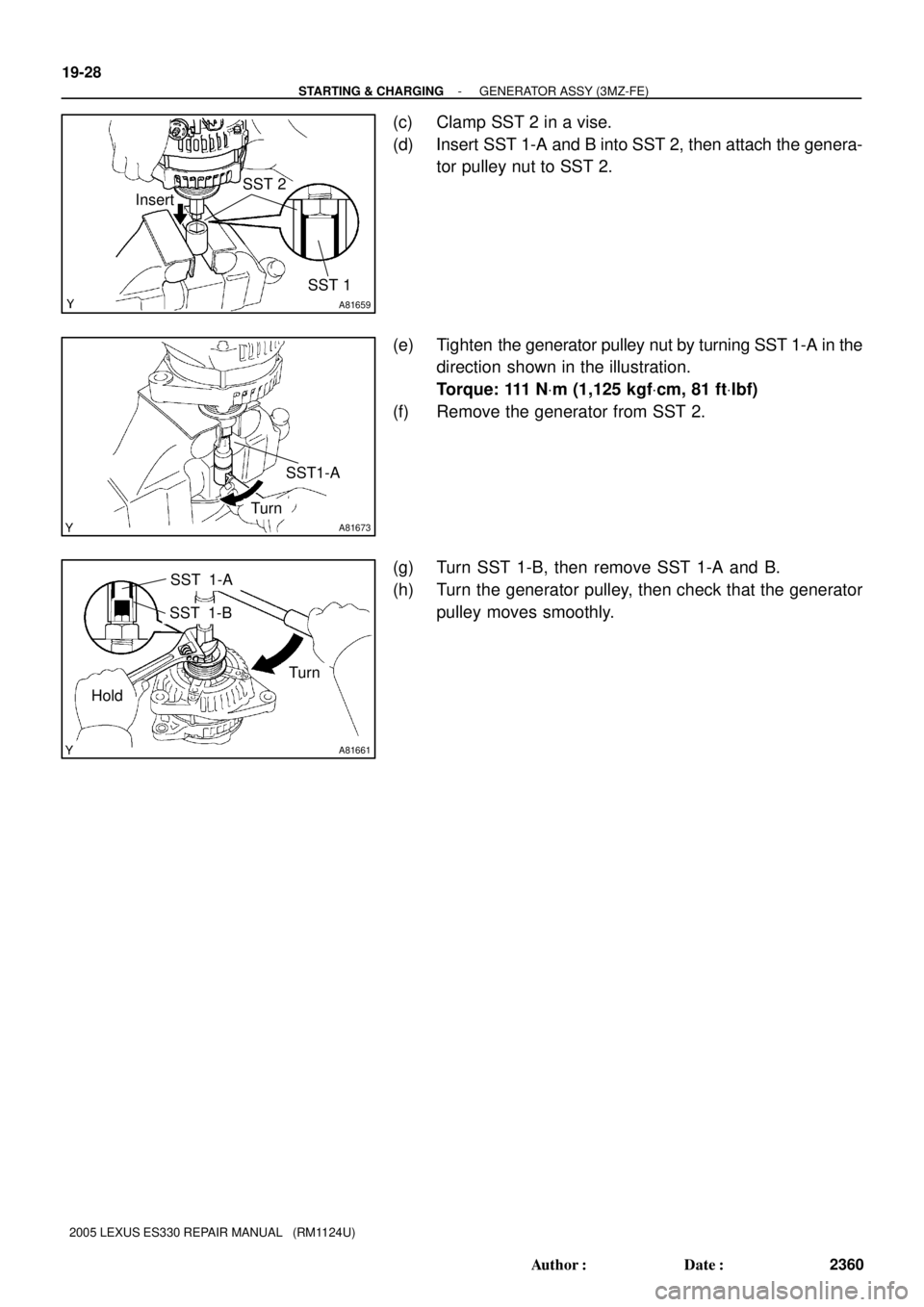
(c) Clamp SST 2 in a vise.
(d) Insert SST 1-A and B into SST 2, then attach the genera-
tor pulley nut to SST 2.
(e) Tighten the generator pulley nut by turning SST 1-A in the
direction shown in the illustration.
Torque: 111 NVm (1,125 kgfVcm, 81 ftVlbf)
(f) Remove the generator from SST 2.
(g) Turn SST 1-B, then remove SST 1-A and B.
(h) Turn the generator pulley, then check that the generator
pulley moves smoothly.
Page 814 of 969
R00429
Marked Line
F16018
- STEERING COLUMNSTEERING
50-5
2566 Author�: Date�:
2005 LEXUS ES330 REPAIR MANUAL (RM1124U)
(1) Draw a line on the RH and LH tie rod and rack ends
where it can easily be seen.
(2) Using a paper gauge, measure the distance from
RH and LH tie rod ends to the rack end screws.
HINT:
�Measure the RH side and LH side.
�Make a note of the measured values.
(3) Remove the RH and LH boot clips from the rack
boots.
(4) Loosen the RH and LH lock nuts.
(5) Turn the RH and LH rack end by the same amount
(but in different directions) according to the steering
angle.
1 turn 360 deg. of rack end (1.5 mm (0.059 in.) horizon-
tal movement) - 12 deg. of steering angle.
(6) Tighten the RH and LH lock nuts.
Torque: 74 NVm (755 kgfVcm, 55 ftVlbf)
NOTICE:
Make sure that the difference in length between RH and LH
tie rod ends and rack end screws are within 1.5 mm (0.059
in.).
(7) Install the RH and LH boot clips.
Page 815 of 969
5002H-02
C90698
Steering Column
CoverHorn Button Assy
Steering Wheel Assy
Steering Pad SwitchConnector
Cover
Turn Signal Switch Assy
50 (510, 37)
Steering Column Cover
Lower No.2Instrument Panel
Finish Plate
NVm (kgfVcm, ftVlbf) : Specified torque
21 (214, 15)
8.8 (90, 78 in.Vlbf)
Steering Wheel
Cover Lower No. 2
Instrument Panel Sub-assy Upper
Steering Column Assy
Steering Column Hole
Cover Sub-assy No. 2
Hose Clamp
Heater to Foot
Duct No. 3
Steering Intermediate
Shaft Sub-assyInstrument Panel Insert
Sub-assy Lower LH
Front Door Scuff Plate LH
35 (360, 26)
35 (360, 26)
21 (214, 15)
50-6
- STEERING COLUMNSTEERING COLUMN ASSY
2567 Author�: Date�:
2005 LEXUS ES330 REPAIR MANUAL (RM1124U)
STEERING COLUMN ASSY
COMPONENTS
Page 816 of 969
C92308
NVm (kgfVcm, ftVlbf) : Specified torque
35 (360, 26)
��Non-reusable partUn-lock Waring
Switch AssyTransponder Key Amplifier
Ignition Switch Lock
Cylinder Assy
Steering Column Upper
w/ Switch Bracket Assy
Steering Column Assy
Ignition or Starter
Switch Assy
Steering Sliding
Yoke Sub-assySteering Column
Clamp Upper
� Tapered-Head Bolt
- STEERING COLUMNSTEERING COLUMN ASSY
50-7
2568 Author�: Date�:
2005 LEXUS ES330 REPAIR MANUAL (RM1124U)
Page 821 of 969
 Temporarily install")
C90694
C90697
C90844H41505
Matchmarks
C90689
Matchmarks
50-12
- STEERING COLUMNSTEERING COLUMN ASSY
2573 Author�: Date�:
32. INSTALL STEERING COLUMN UPPER W/SWITCH
BRACKET ASSY
(a) Temporarily install the steering column upper w/switch
bracket assy and steering column upper clamp with 2 new
tapered-head bolts.
(b) Tighten the 2 tapered-head bolts until the bolt heads
break off.
33. INSTALL TRANSPONDER KEY AMPLIFIER
(a) Align the transponder key amplifier with the installation
position of the upper bracket with the amplifier inclined.
(b) Push the transponder key amplifier up and connect it to
the upper bracket.
NOTICE:
Take care not to push the amplifier up with excessive force
to prevent it from being damaged.
34. INSTALL STEERING SLIDING YOKE SUB-ASSY
(a) Align the matchmarks on the steering sliding yoke sub-
assy and steering main shaft assy.
(b) Install the steering sliding yoke sub-assy with the bolt.
Torque: 35 NVm (360 kgfVcm, 26 ftVlbf)
35. INSTALL STEERING COLUMN HOLE COVER SUB-ASSY NO.2
(a) Install the steering column hole cover sub-assy No.2.
(b) Install the hose clamp.
36. INSTALL STEERING INTERMEDIATE SHAFT
SUB-ASSY
(a) Align the matchmarks on the intermediate shaft sub-assy
and steering gear assy.
(b) Install the steering intermediate shaft sub-assy with the
bolt.
Torque: 35 NVm (360 kgfVcm, 26 ftVlbf)
Page 822 of 969
 Install the steering column assy with the 2 nuts and bolt.
Torque: 21 NVm")
C90690
C90688
Matchmarks
- STEERING COLUMNSTEERING COLUMN ASSY
50-13
2574 Author�: Date�:
37. INSTALL STEERING COLUMN ASSY
(a) Install the steering column assy with the 2 nuts and bolt.
Torque: 21 NVm (214 kgfVcm, 15 ftVlbf)
(b) Connect the driver side junction block.
(c) Connect the connectors and wire harness clamps.
38. CONNECT STEERING SLIDING YOKE SUB-ASSY
(a) Align the matchmarks on the steering sliding yoke sub-
assy and steering intermediate shaft sub-assy.
(b) Connect the steering sliding yoke sub-assy with the bolt.
Torque: 35 NVm (360 kgfVcm, 26 ftVlbf)
39. CONNECT FLOOR SHIFT PARKING LOCK CABLE ASSY
(a) Place the ignition switch lock cylinder assy at the key ACC position.
(b) Install the floor shift parking lock cable assy.
40. INSPECT CHECK KEY INTERLOCK OPERATION(See page 40-31)
41. INSTALL INSTRUMENT PANEL FINISH PLATE(See page 71-1 1)
42. INSTALL TURN SIGNAL SWITCH ASSY
(a) Install the turn signal switch assy with the 3 screws.
(b) Connect the airbag connector.
(c) Connect the 3 connectors.
43. INSPECT SPIRAL CABLE SUB-ASSY(See page 60-31)
44. INSTALL STEERING COLUMN COVER
(a) Install the steering column cover with the 3 screws.
45. INSTALL STEERING COLUMN COVER LWR NO.2
46. INSTALL HEATER TO FOOT DUCT NO.3(See page 71-1 1)
47. INSTALL INSTRUMENT PANEL INSERT SUB-ASSY LOWER LH
48. INSTALL INSTRUMENT PANEL SUB-ASSY UPPER
49. INSTALL FRONT DOOR SCUFF PLATE LH
50. PLACE FRONT WHEELS FACING STRAIGHT AHEAD
Page 823 of 969
50-14
- STEERING COLUMNSTEERING COLUMN ASSY
2575 Author�: Date�:
51. INSTALL STEERING WHEEL ASSY
(a) Align the matchmarks on the steering wheel assy and steering main shaft assy.
(b) Install the steering wheel assy set nut.
Torque: 50 NVm (510 kgfVcm, 37 ftVlbf)
52. INSPECT HORN BUTTON ASSY(See page 60-22)
53. INSTALL HORN BUTTON ASSY(See page 60-22)
54. INSTALL STEERING PAD SWITCH
(a) Connect the connector.
(b) Install the steering pad switch with the 2 screws.
55. INSTALL CONNECTOR COVER
56. INSTALL STEERING WHEEL COVER LOWER NO.2
57. INSPECT SRS WARNING LIGHT(See page 05-818)


Steering Column Cover
Lower No.2Instrument Panel
Fini")