Page 421 of 969

A78712
10
12
3
4
5
67
89
A78713
10
1
2
3
4
5
6
7
89
A05739
A78714Convex Portion
- ENGINE MECHANICALPARTIAL ENGINE ASSY (3MZ-FE)
14-45
2137 Author�: Date�:
2005 LEXUS ES330 REPAIR MANUAL (RM1124U)
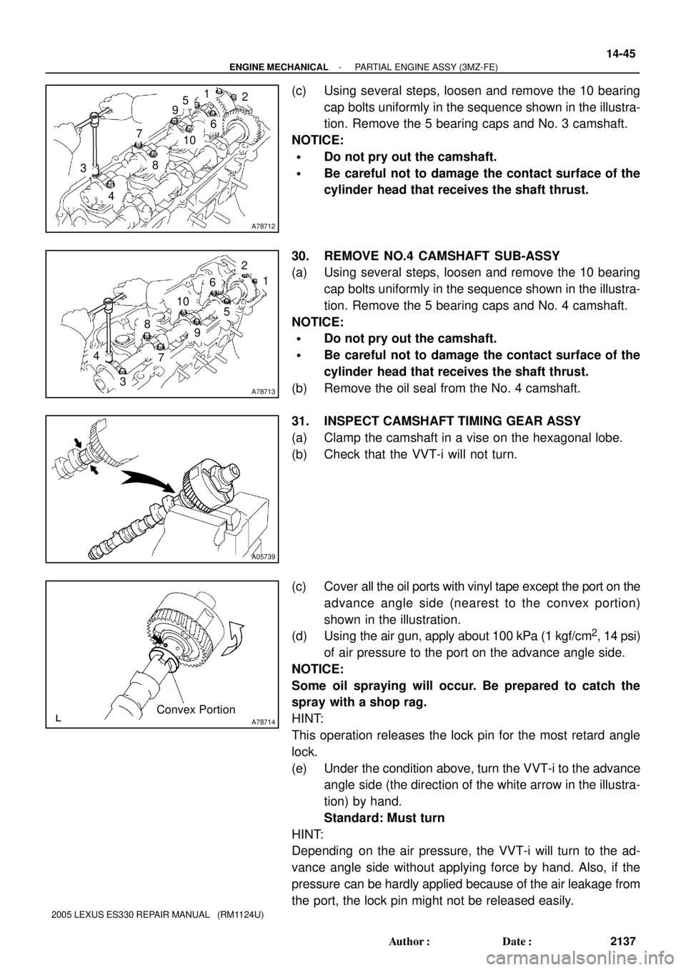
(c) Using several steps, loosen and remove the 10 bearing
cap bolts uniformly in the sequence shown in the illustra-
tion. Remove the 5 bearing caps and No. 3 camshaft.
NOTICE:
�Do not pry out the camshaft.
�Be careful not to damage the contact surface of the
cylinder head that receives the shaft thrust.
30. REMOVE NO.4 CAMSHAFT SUB-ASSY
(a) Using several steps, loosen and remove the 10 bearing
cap bolts uniformly in the sequence shown in the illustra-
tion. Remove the 5 bearing caps and No. 4 camshaft.
NOTICE:
�Do not pry out the camshaft.
�Be careful not to damage the contact surface of the
cylinder head that receives the shaft thrust.
(b) Remove the oil seal from the No. 4 camshaft.
31. INSPECT CAMSHAFT TIMING GEAR ASSY
(a) Clamp the camshaft in a vise on the hexagonal lobe.
(b) Check that the VVT-i will not turn.
(c) Cover all the oil ports with vinyl tape except the port on the
advance angle side (nearest to the convex portion)
shown in the illustration.
(d) Using the air gun, apply about 100 kPa (1 kgf/cm
2, 14 psi)
of air pressure to the port on the advance angle side.
NOTICE:
Some oil spraying will occur. Be prepared to catch the
spray with a shop rag.
HINT:
This operation releases the lock pin for the most retard angle
lock.
(e) Under the condition above, turn the VVT-i to the advance
angle side (the direction of the white arrow in the illustra-
tion) by hand.
Standard: Must turn
HINT:
Depending on the air pressure, the VVT-i will turn to the ad-
vance angle side without applying force by hand. Also, if the
pressure can be hardly applied because of the air leakage from
the port, the lock pin might not be released easily.
Page 422 of 969

A05739
A05740
P12596
14-46
- ENGINE MECHANICALPARTIAL ENGINE ASSY (3MZ-FE)
2138 Author�: Date�:
2005 LEXUS ES330 REPAIR MANUAL (RM1124U)
(f) Check that the VVT-i moves freely within about 30�
range. Avoid moving the VVT-i unit to the most retard
angle position as the lock pin will engage again.
Standard: Smooth movable range is about 30�
(g) Turn the VVT-i by hand, then lock it at the most retard
angle position.
32. REMOVE CAMSHAFT TIMING GEAR ASSY
NOTICE:
Do not remove or install the camshaft timing gear (VVT-i)
unless you are replacing the VVT-i or camshaft.
(a) Clamp the camshaft in a vise on the hexagonal lobe.
NOTICE:
Be careful not to damage the camshaft.
(b) Using a 46 mm socket wrench, remove the lock nut by
turning it clockwise.
NOTICE:
�Remove it with the lock pin engaged and locked at the
most retard angle position.
�The lock nut has LH threads.
�Never use any tools other than the socket wrench.
Other tools will deform the cam angle rotor.
(c) Remove the camshaft VVT-i.
NOTICE:
Never remove the 3 bolts on the gear.
If it is difficult to remove VVT-i, tap it lightly using a plastic-faced
hammer, then remove it.
33. REMOVE CAMSHAFT SUB GEAR
(a) Clamp the camshaft in a vise on the hexagonal lobe.
NOTICE:
Be careful not to damage the camshaft.
Page 427 of 969

A62375
A05245
A05243
EM3336
- ENGINE MECHANICALPARTIAL ENGINE ASSY (3MZ-FE)
14-51
2143 Author�: Date�:
2005 LEXUS ES330 REPAIR MANUAL (RM1124U)
51. REMOVE OIL PUMP SEAL
(a) Using a screwdriver, pry out the oil seal.
52. REMOVE SPARK PLUG TUBE GASKET
(a) Bend up the tab on the ventilation baffle plate which pre-
vents the gasket from slipping out.
NOTICE:
Be careful not to damage the baffle plate of the cylinder
head cover.
(b) Using a screwdriver and hammer, tap out the gasket.
(c) Using needle-nose pliers, pry out the gasket.
NOTICE:
Be careful not to damage the cylinder head cover.
53. INSPECT TIMING BELT
NOTICE:
�Do not bend, twist or turn the timing belt inside out.
�Do not allow contact of the timing belt with oil, water
or steam.
�Do not use the timing belt tension when installing or
removing the mounting bolt of the camshaft timing
pulley.
Check the belt for any defects as shown in the illustrations.
Also, check these points below.
(a) If the belt tears in a short time:
�Check if the belt is installed properly.
�Check if the timing cover gasket is damaged and if
it is installed properly.
(b) If the belt teeth are cracked or damaged, check if either
camshaft is locked.
(c) If there is noticeable wear or cracks on the belt face,
check if there are nicks on the side of the idler pulley lock
and water pump.
Page 428 of 969

EM1628
A51428
A51429
A78721
Tension Portion 14-52
- ENGINE MECHANICALPARTIAL ENGINE ASSY (3MZ-FE)
2144 Author�: Date�:
2005 LEXUS ES330 REPAIR MANUAL (RM1124U)
(d) If there is wear or damage on only one side of the belt,
check the belt guide and alignment of each pulley.
(e) If there is noticeable wear on the belt teeth:
�Check the timing cover for damage.
�Check that the gasket has been installed correctly.
�Check for foreign objects on the pulley teeth.
If there is any doubt about the belt condition, replace the timing
belt.
54. INSPECT CAMSHAFT
(a) Inspect the camshaft for runout.
(1) Place the camshaft on V-blocks.
(2) Using a dial indicator, measure the runout at the
center journal.
Maximum circle runout: 0.06 mm (0.0024 in.)
If the runout is greater than maximum, replace the camshaft.
(b) Inspect the cam lobes.
(1) Using a micrometer, measure the cam lobe height.
Standard cam lobe height:
43.132 to 43.232 mm (1.6981 to 1.7020 in.) for intake
43.010 to 43.110 mm (1.6933 to 1.6972 in.) for exhaust
Minimum cam lobe height:
42.98 mm (1.6921 in.) for intake
42.86 mm (1.6874 in.) for exhaust
If the cam lobe height is less than minimum, replace the cam-
shaft.
(c) Inspect the camshaft journals.
(1) Using a micrometer, measure the journal diameter.
Journal diameter:
26.959 to 26.975 mm (1.0614 to 1.0620 in.)
If the journal diameter is not as specified, check the oil clear-
ance.
55. INSPECT CYLINDER HEAD SET BOLT
(a) Using vernier calipers, measure the tension portion diam-
eter of the bolt.
Standard outside diameter:
8.95 to 9.05 mm (0.3524 to 0.3563 in.)
Minimum outside diameter: 8.75 mm (0.3445 in.)
If the diameter is less than minimum, replace the bolt.
Page 433 of 969

A78324
Front
A78717
1
2
3
4
5
67
8
Front
A78730
90�
Front
Painted Mark
A78716
Front
- ENGINE MECHANICALPARTIAL ENGINE ASSY (3MZ-FE)
14-57
2149 Author�: Date�:
2005 LEXUS ES330 REPAIR MANUAL (RM1124U)
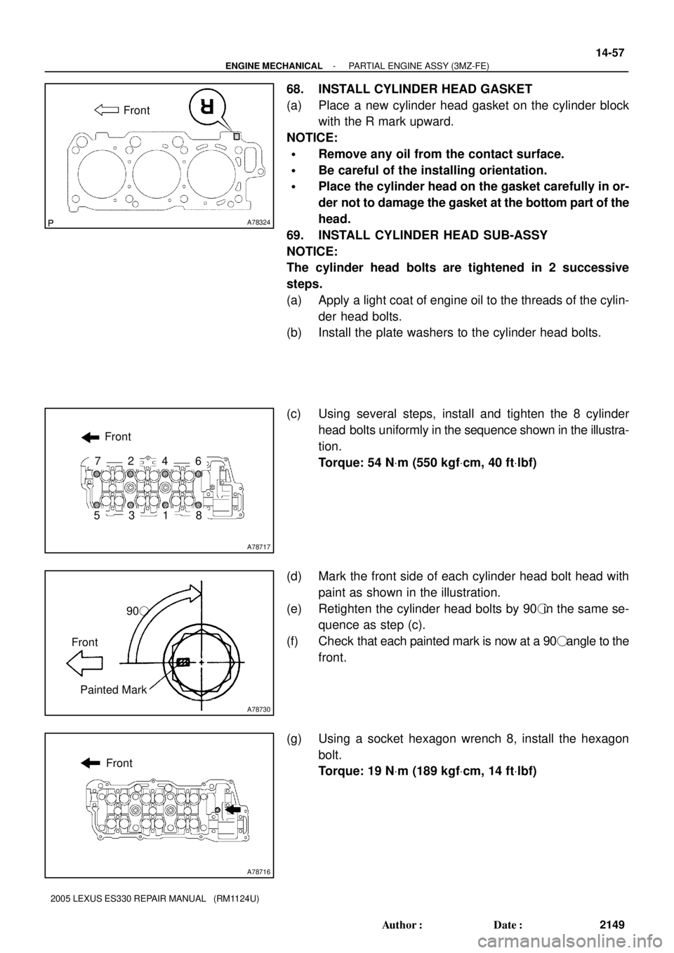
68. INSTALL CYLINDER HEAD GASKET
(a) Place a new cylinder head gasket on the cylinder block
with the R mark upward.
NOTICE:
�Remove any oil from the contact surface.
�Be careful of the installing orientation.
�Place the cylinder head on the gasket carefully in or-
der not to damage the gasket at the bottom part of the
head.
69. INSTALL CYLINDER HEAD SUB-ASSY
NOTICE:
The cylinder head bolts are tightened in 2 successive
steps.
(a) Apply a light coat of engine oil to the threads of the cylin-
der head bolts.
(b) Install the plate washers to the cylinder head bolts.
(c) Using several steps, install and tighten the 8 cylinder
head bolts uniformly in the sequence shown in the illustra-
tion.
Torque: 54 NVm (550 kgfVcm, 40 ftVlbf)
(d) Mark the front side of each cylinder head bolt head with
paint as shown in the illustration.
(e) Retighten the cylinder head bolts by 90�in the same se-
quence as step (c).
(f) Check that each painted mark is now at a 90� angle to the
front.
(g) Using a socket hexagon wrench 8, install the hexagon
bolt.
Torque: 19 NVm (189 kgfVcm, 14 ftVlbf)
Page 434 of 969

A79822
Front
A78719
1
2
3
4
5
67
8
Front
A78730
90�
Front
Painted Mark
A78718
Front 14-58
- ENGINE MECHANICALPARTIAL ENGINE ASSY (3MZ-FE)
2150 Author�: Date�:
2005 LEXUS ES330 REPAIR MANUAL (RM1124U)
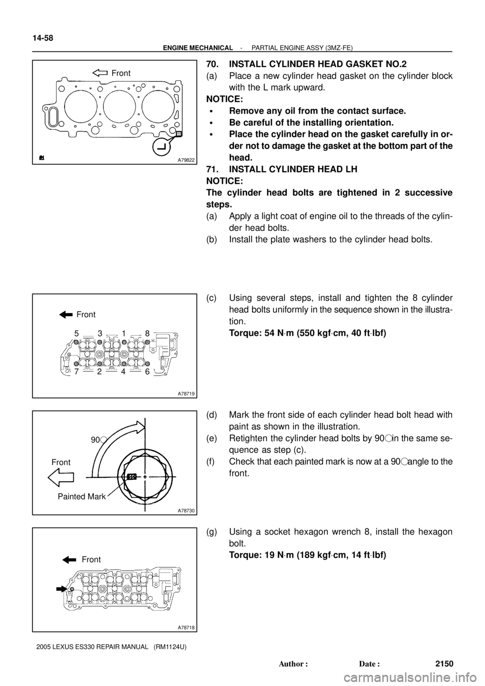
70. INSTALL CYLINDER HEAD GASKET NO.2
(a) Place a new cylinder head gasket on the cylinder block
with the L mark upward.
NOTICE:
�Remove any oil from the contact surface.
�Be careful of the installing orientation.
�Place the cylinder head on the gasket carefully in or-
der not to damage the gasket at the bottom part of the
head.
71. INSTALL CYLINDER HEAD LH
NOTICE:
The cylinder head bolts are tightened in 2 successive
steps.
(a) Apply a light coat of engine oil to the threads of the cylin-
der head bolts.
(b) Install the plate washers to the cylinder head bolts.
(c) Using several steps, install and tighten the 8 cylinder
head bolts uniformly in the sequence shown in the illustra-
tion.
Torque: 54 NVm (550 kgfVcm, 40 ftVlbf)
(d) Mark the front side of each cylinder head bolt head with
paint as shown in the illustration.
(e) Retighten the cylinder head bolts by 90� in the same se-
quence as step (c).
(f) Check that each painted mark is now at a 90� angle to the
front.
(g) Using a socket hexagon wrench 8, install the hexagon
bolt.
Torque: 19 NVm (189 kgfVcm, 14 ftVlbf)
Page 435 of 969
A05418
P12595
A78732
Camshaft
Sub Gear
Camshaft Gear
Bolt Washer Wave Washer
A52353
- ENGINE MECHANICALPARTIAL ENGINE ASSY (3MZ-FE)
14-59
2151 Author�: Date�:
2005 LEXUS ES330 REPAIR MANUAL (RM1124U)
72. INSTALL OIL CONTROL VALVE FILTER
(a) Check that no foreign object is on the mesh part of the fil-
ter.
(b) Assemble the valve filter and plug.
(c) Install the plug with a new gasket.
Torque: 45 NVm (459 kgfVcm, 33 ftVlbf)
73. INSTALL CYLINDER HEAD COVER REAR
(a) Install the rear cover and a new gasket.
Torque: 10 NVm (102 kgfVcm, 7 ftVlbf)
74. INSTALL CAMSHAFT SUB GEAR
(a) Clamp the camshaft in a vise on the hexagonal lobe.
NOTICE:
Be careful not to damage the camshaft.
(b) Install the camshaft gear bolt washer and camshaft sub
gear.
HINT:
Attach the pins on the gears to the gear bolt washer ends.
(c) Install the wave washer.
(d) Using snap ring pliers, install the snap ring.
Page 441 of 969

A78535
A78747
SST
Additional
3/4 Turn
- ENGINE MECHANICALPARTIAL ENGINE ASSY (3MZ-FE)
14-65
2157 Author�: Date�:
2005 LEXUS ES330 REPAIR MANUAL (RM1124U)
81. INSTALL WATER PUMP ASSY
(a) Install a new gasket and the water pump with the 3 bolts
and 3 nuts.
Torque: 8.0 NVm (82 kgfVcm, 71 in.Vlbf)
82. INSTALL OIL LEVEL GAGE GUIDE
(a) Apply a light coat of engine oil to a new O-ring, then install it to the level gage guide.
(b) Install the level gage guide.
Torque: 8.0 NVm (82 kgfVcm, 71 in.Vlbf)
83. INSTALL OIL FILTER SUB-ASSY
(a) Using a socket hexagon wrench 12, install the oil filter
union.
Torque: 30 NVm (306 kgfVcm, 22 ftVlbf)
(b) Check and clean the oil filter installation surface.
(c) Apply clean engine oil to the gasket of a new oil filter.
(d) Lightly screw the oil filter into place, then tighten it until the
gasket contacts the seat.
(e) Using SST, tighten it by an additional 3/4 turn.
SST 09228-07501
84. INSTALL TIMING BELT IDLER BRACKET
Torque: 28 NVm (286 kgfVcm, 21 ftVlbf)
85. INSTALL TIMING BELT NO.3 COVER
(a) Visually check for cracks and breaks on the gasket of the
timing belt cover.
HINT:
If there is a trace of water intrusion when checking visually, re-
pair the gasket with seal packing when the crack length is within
2 to 3 cm (0.79 to 1.18 in.). Replace the gasket when the crack
length is 3 to 4 cm (1.18 to 1.57 in.) or longer.