Page 746 of 969

17. REMOVE STEERING LEFT TUR")
F41497
SST
F41498
SST
F40050
Matchmarks
ZK8184
51-24
- POWER STEERINGRACK & PINION POWER STEERING GEAR ASSY
2599 Author�: Date�:
2005 LEXUS ES330 REPAIR MANUAL (RM1124U)
17. REMOVE STEERING LEFT TURN PRESSURE TUBE
(a) Using SST, remove the steering left turn pressure tube.
SST 09023-38201
(b) Remove the 2 O-rings from the steering left turn pressure
tube.
18. REMOVE STEERING RIGHT TURN PRESSURE TUBE
(a) Using SST, remove the steering right turn pressure tube.
SST 09023-38201
(b) Remove the 2 O-rings from the steering right turn pres-
sure tube.
19. FIX RACK & PINION POWER STEERING GEAR ASSY
(a) Using SST, secure the rack & pinion power steering gear
assy.
SST 09612-00012
HINT:
Tape the SST before use.
20. REMOVE TIE ROD ASSY LH
(a) Place matchmarks on the tie rod assy LH and steering
rack end sub-assy.
(b) Loosen the lock nut, and remove the tie rod assy LH and
lock nut.
21. REMOVE TIE ROD ASSY RH
HINT:
Remove the RH side by the same procedures with LH side.
22. INSPECT TIE ROD ASSY LH
(a) Secure the tie rod assy LH in a vise.
(b) Install the nut to the stud bolt.
(c) Flip the ball joint stud back and forth 5 times.
(d) Using a torque wrench, turn the nut continuously at a rate
of 2 - 4 seconds per 1 turn and take the torque reading
of the 5th turn.
Turning torque:
0.83 - 3.43 NVm (8.5 - 35.0 kgfVcm, 7.3 - 30.4 in.Vlbf)
23. INSPECT TIE ROD ASSY RH
HINT:
Remove the RH side by the same procedures with LH side.
Page 756 of 969

F41515SST
F41516
SST
F41517
SST
SST
Rack Guide
Spring Cap
F41518SSTFulcrum Length Rack Guide Spring
Cap Nut
SST
51-34
- POWER STEERINGRACK & PINION POWER STEERING GEAR ASSY
2609 Author�: Date�:
2005 LEXUS ES330 REPAIR MANUAL (RM1124U)
(c) Using SST, loosen the rack guide spring cap.
SST 09631-10021
(d) Using SST, turn the control valve to the right and left 1 or
2 times.
SST 09616-0001 1
(e) Using SST, loosen the rack guide spring cap until the
compression spring is not functioning.
SST 09631-10021
(f) Using SST and a torque wrench, tighten the rack guide
spring cap until the preload is within specification.
SST 09616-0001 1, 09631-10021
Preload (turning):
1.2 - 1.5 NVm (12.2 - 15.3 kgfVcm, 10.6 - 13.3 in.Vlbf)
(g) Apply sealant to 2 or 3 threads of the rack guide spring
cap nut.
Sealant:
Part No. 08833-00080, THREE BOND 1344, LOCTITE
242 or equivalent
(h) Temporarily install the rack guide spring cap nut.
(i) Using SST, hold the rack guide spring cap and using
another SST, tighten the rack guide spring cap nut.
SST 09616-0001 1, 09922-10010
Torque: 48 NVm (489 kgfVcm, 35 ftVlbf)
NOTICE:
Use SST 09922-10010 in the direction shown in the illustra-
tion.
HINT:
Use a torque wrench with a fulcrum length of 345 mm (13.58
in.).
(j) Precheck the total preload.
Preload (turning):
1.2 - 1.5 NVm (12.2 - 15.3 kgfVcm, 10.6 - 13.3 in.Vlbf)
(k) Remove the RH and LH steering rack ends sub-assy.
Page 758 of 969

50. INSPECT STEERING RACK END SUB-ASSY
(a) Ensure t")
ZX9390F41951
F40556
SST
51-36
- POWER STEERINGRACK & PINION POWER STEERING GEAR ASSY
2611 Author�: Date�:
2005 LEXUS ES330 REPAIR MANUAL (RM1124U)
50. INSPECT STEERING RACK END SUB-ASSY
(a) Ensure that the steering rack end sub-assy hole is not
clogged with grease.
HINT:
If the hole is clogged, the pressure inside the boot will change
after it is assembled and steering wheel is turned.
51. INSTALL STEERING RACK BOOT NO.2
(a) Install the steering rack boot No.2.
52. INSTALL STEERING RACK BOOT NO.1
HINT:
Remove the steering rack boot No.1 by the same procedures with steering rack boot No.2.
53. INSTALL STEERING RACK BOOT NO.2 CLAMP
(a) Using SST, tighten the steering rack boot No.2 clamp, as
shown in the illustration.
SST 09521-24010
Clearance: 3.0 mm (0.118 in.) or less
NOTICE:
Be careful not to damage the steering rack boot No.2.
54. INSTALL STEERING RACK BOOT NO.1 CLAMP
SST 09521-24010
NOTICE:
Be careful not to damage the steering rack boot No.1.
HINT:
Install the steering rack boot No.1 clamp by the same proce-
dures with steering rack boot No.2 clamp.
55. INSTALL STEERING RACK BOOT CLIP
(a) Using pliers, install the 2 steering rack boot clips.
56. INSTALL TIE ROD ASSY LH
(a) Screw the lock nut and tie rod assy LH onto the steering rack end sub-assy until the matchmarks are
aligned.
HINT:
After adjusting toe-in, torque the lock nut.
57. INSTALL TIE ROD ASSY RH
HINT:
Install the RH side by the same procedures with LH side.
Page 762 of 969
51-40
- POWER STEERINGRACK & PINION POWER STEERING GEAR ASSY
2615 Author�: Date�:
2005 LEXUS ES330 REPAIR MANUAL (RM1124U)
68. CONNECT TIE ROD ASSY LH
(a) Connect the tie rod assy LH with the nut.
Torque: 49 NVm (500 kgfVcm, 36 ftVlbf)
(b) Install a new cotter pin.
NOTICE:
If the holes for a new cotter pin are not aligned, tighten the nut further up 60�.
69. CONNECT TIE ROD ASSY RH
HINT:
Install the RH side by the same procedures with LH side.
70. INSTALL FRONT WHEEL
Torque: 103 NVm (1,050 kgfVcm, 76 ftVlbf)
71. BLEED POWER STEERING FLUID (See page 51-3)
72. CHECK POWERSTEERING FLUID LEAKAGE
73. INSTALL SPIRAL CABLE SUB-ASSY
(See page 50-8)
74. CENTER SPIRAL CABLE(See page 50-8)
75. INSTALL STEERING WHEEL ASSY
(See page 50-8)
76. INSTALL HORN BUTTON ASSY
(See page 60-22)
77. INSPECT AND ADJUST FRONT WHEEL ALIGNMENT(See page 26-5)
78. INSPECT STEERING WHEEL CENTER POINT
79. INSPECT SRS WARNING LIGHT(See page 05-826)
Page 764 of 969
2704V-06
C92643
Rear Suspension Member
Sub-Assy
Rear Suspension Support
No. 1 Cover LH
Collar
Suspension Support
Spring Bumper
Coil Spring
Lower Insulator Rear Suspension
Arm Assy No. 2 LH
Rear Suspension
Arm Assy No. 1 LH
Strut Rod Assy Rear
Bracket
Bushing
Shock Absorber
Assy Rear LH Rear Stabilizer
Link Assy LH Stabilizer Bar Rear Parking Brake Cable
NVm (kgfVcm, ftVlbf) : Specified torque
49 (500, 36)
39 (400, 29)
55 (561, 41)
100 (1,020, 74)
100 (1,020, 74)
113 (1,150, 83)
39 (400, 29)
19 (195, 14)
5.4 (55, 48 in.Vlbf)
255 (2,600, 188)
113 (1,150, 83)
100 (1,020, 74)
100 (1,020, 74)
55 (561, 41)
38 (387, 28)
RH Side:
w/TEMS:
19 (195, 14)
�
�Non-reusable partw/o TEMS:5.4 (55, 48 in.Vlbf)
27-2
- REAR SUSPENSIONREAR SUSPENSION
2384 Author�: Date�:
2005 LEXUS ES330 REPAIR MANUAL (RM1124U)
REAR SUSPENSION
COMPONENTS
Page 765 of 969

REAR WHEEL ALIGNMENT
ADJUSTMENT
1. INSPECT TIRE (S")
2704P-06
SA3213
A
DB
Front
C
C91810
C91811
- REAR SUSPENSIONREAR WHEEL ALIGNMENT
27-3
2385 Author�: Date�:
2005 LEXUS ES330 REPAIR MANUAL (RM1124U)
REAR WHEEL ALIGNMENT
ADJUSTMENT
1. INSPECT TIRE (See page 28-1)
2. MEASURE VEHICLE HEIGHT (See page 26-5)
NOTICE:
Before inspecting the wheel alignment, adjust the vehicle height to the specified value.
3. INSPECT TOE-IN
Toe-in:
Toe-in
(total)A + B: 0°22' ± 11' (0.4° ± 0.2°)
C - D: 4 ± 2 mm (0.16 ± 0.08 in.)
If the toe-in is not within the specified value, inspect and re-
place the suspension parts if necessary.
4. ADJUST TOE-IN
(a) Measure the lengths of the right and left No. 2 lower sus-
pension arms.
No. 2 lower suspension arm length difference:
1.0 mm (0.039 in.) or less
If the left-right difference is larger than 1.0 mm (0.039 in.), ad-
just it by following the procedures below.
(b) Loosen the lock nuts.
(c) Turn the right and left adjusting tube by an equal amount
to adjust toe-in.
HINT:
�Try to adjust the toe-in to the center value.
�One turn of the each adjusting tube will adjust the toe-in
by approximately 67' (1�12', 10.8 mm, 0.425 in.).
(d) Torque the lock nut.
Torque: 56 NVm (570 kgfVcm, 41 ftVlbf)
5. INSPECT CAMBER
Camber
Right-left error-1°23' ± 45' (-1.38° ± 0.75°)
45' (0.75°) or less
HINT:
Camber is not adjustable. If the measurement is not within the specification, inspect the suspension parts
for damaged and/or worn-out parts and replace them if necessary.
Page 770 of 969
C92644
w/o TEMS
w/ TEMSSST
C66631
27-8
- REAR SUSPENSIONSHOCK ABSORBER ASSY REAR LH
2390 Author�: Date�:
2005 LEXUS ES330 REPAIR MANUAL (RM1124U)
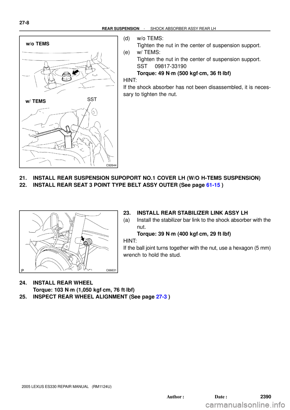
(d) w/o TEMS:
Tighten the nut in the center of suspension support.
(e) w/ TEMS:
Tighten the nut in the center of suspension support.
SST 09817-33190
Torque: 49 NVm (500 kgfVcm, 36 ftVlbf)
HINT:
If the shock absorber has not been disassembled, it is neces-
sary to tighten the nut.
21. INSTALL REAR SUSPENSION SUPOPORT NO.1 COVER LH (W/O H-TEMS SUSPENSION)
22. INSTALL REAR SEAT 3 POINT TYPE BELT ASSY OUTER (See page 61-15)
23. INSTALL REAR STABILIZER LINK ASSY LH
(a) Install the stabilizer bar link to the shock absorber with the
nut.
Torque: 39 NVm (400 kgfVcm, 29 ftVlbf)
HINT:
If the ball joint turns together with the nut, use a hexagon (5 mm)
wrench to hold the stud.
24. INSTALL REAR WHEEL
Torque: 103 NVm (1,050 kgfVcm, 76 ftVlbf)
25. INSPECT REAR WHEEL ALIGNMENT (See page 27-3)
Page 775 of 969

20. STABILIZE SUSPENSION
(a) Jack up the rear axle carrier,")
C91813
C82996
C82997
- REAR SUSPENSIONREAR SUSPENSION ARM ASSY NO.1 LH
27-13
2395 Author�: Date�:
2005 LEXUS ES330 REPAIR MANUAL (RM1124U)
20. STABILIZE SUSPENSION
(a) Jack up the rear axle carrier, placing a wooden block be-
tween them. Apply load to the suspension so that the
installed bolt of the suspension arm assy No. 1 (vehicle
side) is horizontally aligned with the center of the rear axle
hub.
21. FULLY TIGHTEN REAR SUSPENSION ARM ASSY
NO.1 LH
(a) Fully tighten the bolt.
Torque: 100 NVm (1,020 kgfVcm, 74 ftVlbf)
HINT:
While fixing the nut, turn the bolt.
22. FULLY TIGHTEN REAR SUSPENSION ARM ASSY NO.1 RH
HINT:
Fully tighten the RH side by the procedures with the LH side.
23. FULLY TIGHTEN REAR SUSPENSION ARM ASSY
NO.2 LH
(a) Fully tighten the bolt.
Torque: 100 NVm (1,020 kgfVcm, 74 ftVlbf)
HINT:
While fixing the nut, turn the bolt.
24. FULLY TIGHTEN REAR SUSPENSION ARM ASSY NO.2 RH
HINT:
Fully tighten the RH side by the procedures with the LH side.
25. FULLY TIGHTEN STRUT ROD ASSY REAR (See page 27-18)
26. INSTALL STABILIZER BAR REAR (See page 27-16)
27. INSTALL EXHAUST PIPE ASSY CENTER (See page 15-2)
28. INSTALL REAR WHEEL
Torque: 103 NVm (1,050 kgfVcm, 76 ftVlbf)
29. INSPECT REAR WHEEL ALIGNMENT (See page 27-3)
30. HEADLIGHT AIM ONLY (See page 65-15)