Page 801 of 969
A86392
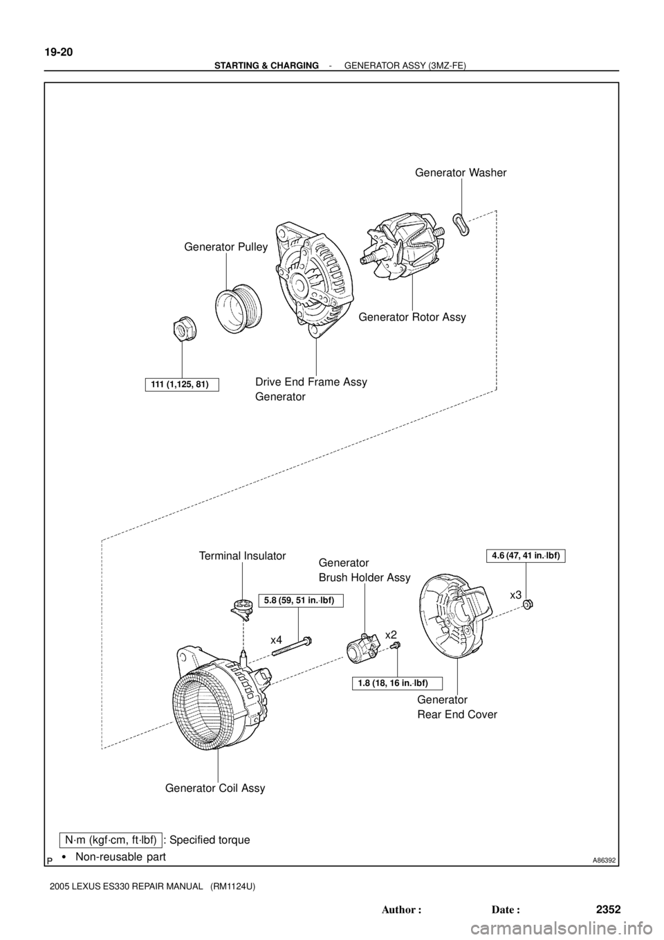
Generator Pulley
Drive End Frame Assy
GeneratorGenerator Rotor AssyGenerator Washer
Generator Coil AssyTerminal Insulator
Generator
Brush Holder Assy
Generator
Rear End Cover
x4
� Non-reusable part
N´m (kgf´cm, ft´lbf) : Specified torque
5.8 (59, 51 in.Vlbf)
1.8 (18, 16 in.Vlbf)
4.6 (47, 41 in.Vlbf)
111 (1,125, 81)
x2x3 19-20
- STARTING & CHARGINGGENERATOR ASSY (3MZ-FE)
2352 Author�: Date�:
2005 LEXUS ES330 REPAIR MANUAL (RM1124U)
Page 803 of 969
A87593
B
A
A87594
B
AC 19-22
- STARTING & CHARGINGGENERATOR ASSY (3MZ-FE)
2354 Author�: Date�:
2005 LEXUS ES330 REPAIR MANUAL (RM1124U)
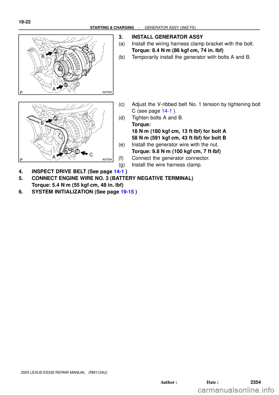
3. INSTALL GENERATOR ASSY
(a) Install the wiring harness clamp bracket with the bolt.
Torque: 8.4 NVm (86 kgfVcm, 74 in.Vlbf)
(b) Temporarily install the generator with bolts A and B.
(c) Adjust the V-ribbed belt No. 1 tension by tightening bolt
C (see page 14-1).
(d) Tighten bolts A and B.
Torque:
18 NVm (180 kgfVcm, 13 ftVlbf) for bolt A
58 NVm (591 kgfVcm, 43 ftVlbf) for bolt B
(e) Install the generator wire with the nut.
Torque: 9.8 NVm (100 kgfVcm, 7 ftVlbf)
(f) Connect the generator connector.
(g) Install the wire harness clamp.
4. INSPECT DRIVE BELT (See page 14-1)
5. CONNECT ENGINE WIRE NO. 3 (BATTERY NEGATIVE TERMINAL)
Torque: 5.4 NVm (55 kgfVcm, 48 in.Vlbf)
6. SYSTEM INITIALIZATION (See page 19-15)
Page 804 of 969
190SM-01
A81658
SST 1-A
SST 1-B
Turn
Hold
A81659
SST 2
Insert
SST 1
A81660
TurnSST1-A
A81661
SST 1-A
SST 1-B
Turn
Hold
- STARTING & CHARGINGGENERATOR ASSY (3MZ-FE)
19-23
2355 Author�: Date�:
2005 LEXUS ES330 REPAIR MANUAL (RM1124U)
OVERHAUL
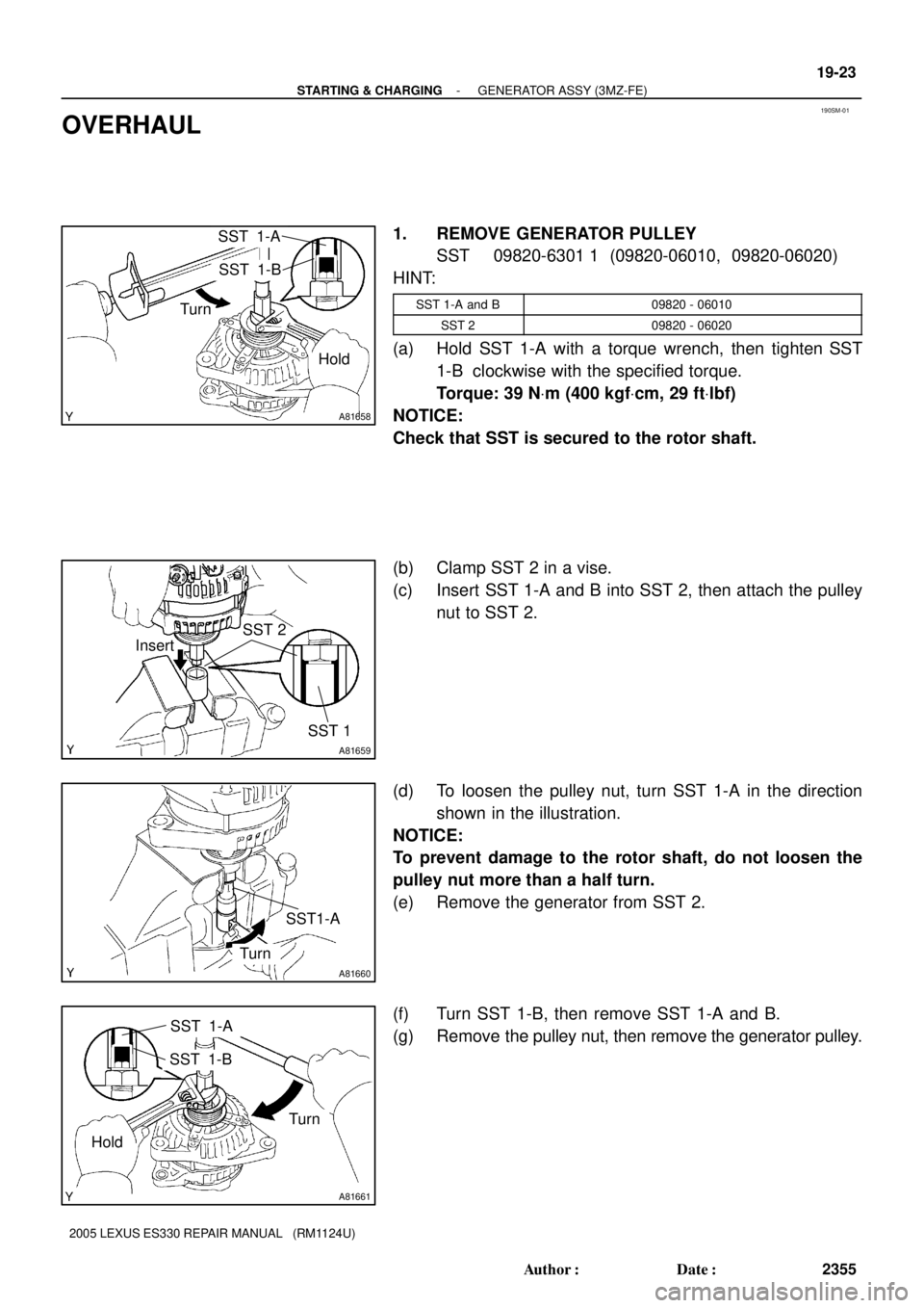
1. REMOVE GENERATOR PULLEY
SST 09820-6301 1 (09820-06010, 09820-06020)
HINT:
SST 1-A and B09820 - 06010
SST 209820 - 06020
(a) Hold SST 1-A with a torque wrench, then tighten SST
1-B clockwise with the specified torque.
Torque: 39 NVm (400 kgfVcm, 29 ftVlbf)
NOTICE:
Check that SST is secured to the rotor shaft.
(b) Clamp SST 2 in a vise.
(c) Insert SST 1-A and B into SST 2, then attach the pulley
nut to SST 2.
(d) To loosen the pulley nut, turn SST 1-A in the direction
shown in the illustration.
NOTICE:
To prevent damage to the rotor shaft, do not loosen the
pulley nut more than a half turn.
(e) Remove the generator from SST 2.
(f) Turn SST 1-B, then remove SST 1-A and B.
(g) Remove the pulley nut, then remove the generator pulley.
Page 807 of 969
A75676
Diameter
A81670
Generator
PulleyGenerator Washer
A81671
Deep Socket
Wrench 21
A81148
A79315
Pin (f1.0 mm (0.039 in.))
19-26
- STARTING & CHARGINGGENERATOR ASSY (3MZ-FE)
2358 Author�: Date�:
2005 LEXUS ES330 REPAIR MANUAL (RM1124U)
(e) Inspect the diameter.
(1) Using vernier calipers, measure the slip ring diame-
ter.
Standard diameter:
14.2 to 14.4 mm (0.559 to 0.567 in.)
Minimum diameter: 14.0 mm (0.551 in.)
If the diameter is less than minimum, replace the generator ro-
tor.
7. INSTALL GENERATOR ROTOR ASSY
(a) Place the generator drive end frame on the generator
pulley.
(b) Install the generator rotor and generator washer.
8. INSTALL GENERATOR COIL ASSY
(a) Using a deep socket wrench 21 and press, press in the
generator coil carefully.
(b) Tighten the 4 bolts.
Torque: 5.8 NVm (59 kgfVcm, 51 in.Vlbf)
9. INSTALL GENERATOR BRUSH HOLDER ASSY
(a) While pushing the 2 brushes to inside the brush holder,
insert a pin (f1.0 mm (0.039 in.)) into the brush holder
hole.
Page 808 of 969

A81146
A81164
A81658
SST 1-A
SST 1-B
Turn
Hold
- STARTING & CHARGINGGENERATOR ASSY (3MZ-FE)
19-27
2359 Author�: Date�:
2005 LEXUS ES330 REPAIR MANUAL (RM1124U)
(b) In")
A81672
Pin (f1.0 mm (0.039 in.)
A81146
A81164
A81658
SST 1-A
SST 1-B
Turn
Hold
- STARTING & CHARGINGGENERATOR ASSY (3MZ-FE)
19-27
2359 Author�: Date�:
2005 LEXUS ES330 REPAIR MANUAL (RM1124U)
(b) Install the generator brush holder with the 2 screws.
Torque: 1.8 NVm (18 kgfVcm, 16 in.Vlbf)
(c) Pull out the pin (f1.0 mm (0.039 in.)) from the generator
brush holder.
(d) Install the terminal insulator.
NOTICE:
Pay attention to the mounting orientation of the terminal in-
sulator.
(e) Install the generator rear end cover with the 3 nuts.
Torque: 4.6 NVm (47 kgfVcm, 41 in.Vlbf)
10. INSTALL GENERATOR PULLEY
SST 09820-6301 1 (09820-06010, 09820-06020)
HINT:
SST 1-A and B09820 - 06010
SST 209820 - 06020
(a) Install the generator pulley to the rotor shaft by tightening
the generator pulley nut by hand.
(b) Hold SST 1-A with a torque wrench, then tighten SST
1-B clockwise with the specified torque.
Torque: 39 NVm (400 kgfVcm, 29 ftVlbf)
NOTICE:
Check that SST is secured to the rotor shaft.
Page 815 of 969
5002H-02
C90698
Steering Column
CoverHorn Button Assy
Steering Wheel Assy
Steering Pad SwitchConnector
Cover
Turn Signal Switch Assy
50 (510, 37)
Steering Column Cover
Lower No.2Instrument Panel
Finish Plate
NVm (kgfVcm, ftVlbf) : Specified torque
21 (214, 15)
8.8 (90, 78 in.Vlbf)
Steering Wheel
Cover Lower No. 2
Instrument Panel Sub-assy Upper
Steering Column Assy
Steering Column Hole
Cover Sub-assy No. 2
Hose Clamp
Heater to Foot
Duct No. 3
Steering Intermediate
Shaft Sub-assyInstrument Panel Insert
Sub-assy Lower LH
Front Door Scuff Plate LH
35 (360, 26)
35 (360, 26)
21 (214, 15)
50-6
- STEERING COLUMNSTEERING COLUMN ASSY
2567 Author�: Date�:
2005 LEXUS ES330 REPAIR MANUAL (RM1124U)
STEERING COLUMN ASSY
COMPONENTS
Page 816 of 969
C92308
NVm (kgfVcm, ftVlbf) : Specified torque
35 (360, 26)
��Non-reusable partUn-lock Waring
Switch AssyTransponder Key Amplifier
Ignition Switch Lock
Cylinder Assy
Steering Column Upper
w/ Switch Bracket Assy
Steering Column Assy
Ignition or Starter
Switch Assy
Steering Sliding
Yoke Sub-assySteering Column
Clamp Upper
� Tapered-Head Bolt
- STEERING COLUMNSTEERING COLUMN ASSY
50-7
2568 Author�: Date�:
2005 LEXUS ES330 REPAIR MANUAL (RM1124U)
Page 822 of 969
 Install the steering column assy with the 2 nuts and bolt.
Torque: 21 NVm")
C90690
C90688
Matchmarks
- STEERING COLUMNSTEERING COLUMN ASSY
50-13
2574 Author�: Date�:
37. INSTALL STEERING COLUMN ASSY
(a) Install the steering column assy with the 2 nuts and bolt.
Torque: 21 NVm (214 kgfVcm, 15 ftVlbf)
(b) Connect the driver side junction block.
(c) Connect the connectors and wire harness clamps.
38. CONNECT STEERING SLIDING YOKE SUB-ASSY
(a) Align the matchmarks on the steering sliding yoke sub-
assy and steering intermediate shaft sub-assy.
(b) Connect the steering sliding yoke sub-assy with the bolt.
Torque: 35 NVm (360 kgfVcm, 26 ftVlbf)
39. CONNECT FLOOR SHIFT PARKING LOCK CABLE ASSY
(a) Place the ignition switch lock cylinder assy at the key ACC position.
(b) Install the floor shift parking lock cable assy.
40. INSPECT CHECK KEY INTERLOCK OPERATION(See page 40-31)
41. INSTALL INSTRUMENT PANEL FINISH PLATE(See page 71-1 1)
42. INSTALL TURN SIGNAL SWITCH ASSY
(a) Install the turn signal switch assy with the 3 screws.
(b) Connect the airbag connector.
(c) Connect the 3 connectors.
43. INSPECT SPIRAL CABLE SUB-ASSY(See page 60-31)
44. INSTALL STEERING COLUMN COVER
(a) Install the steering column cover with the 3 screws.
45. INSTALL STEERING COLUMN COVER LWR NO.2
46. INSTALL HEATER TO FOOT DUCT NO.3(See page 71-1 1)
47. INSTALL INSTRUMENT PANEL INSERT SUB-ASSY LOWER LH
48. INSTALL INSTRUMENT PANEL SUB-ASSY UPPER
49. INSTALL FRONT DOOR SCUFF PLATE LH
50. PLACE FRONT WHEELS FACING STRAIGHT AHEAD


Steering Column Cover
Lower No.2Instrument Panel
Fini")