Page 244 of 969
C93149
C90581
C92829
- AUTOMATIC TRANSMISSION / TRANSTRANSMISSION CONTROL CABLE ASSY
40-45
2560 Author�: Date�:
2005 LEXUS ES330 REPAIR MANUAL (RM1124U)
(e) Disconnect the floor shift cable from the rod of the floor
shift assy.
(f) Remove the 2 bolts and shift cable grommet retainer
No.2.
(g) Pull out the control cable from the body.
9. INSTALL TRANSMISSION CONTROL CABLE ASSY
(a) put in the control cable to the body.
(b) Install the shift cable grommet retainer No.2 to the floor
shift cable.
(c) Install the floor shift cable, as shown in the illustration.
HINT:
Install it with the uneven surface facing up.
Page 245 of 969
C90581
C93327
D25414
D25415
40-46
- AUTOMATIC TRANSMISSION / TRANSTRANSMISSION CONTROL CABLE ASSY
2561 Author�: Date�:
2005 LEXUS ES330 REPAIR MANUAL (RM1124U)
(d) Install the shift cable grommet retainer No.2 with the 2
bolts.
Torque: 4.9 NVm (50 kgfVcm, 43 in.Vlbf)
(e) Connect the control cable to the control cable clamp.
(f) Temporarily install the control cable to the control shaft le-
ver with nuts.
(g) Install the control cable and a new clip to the bracket.
10. INSTALL INTAKE AIR RESONATOR SUB-ASSY
11. INSTALL AIR CLEANER HOSE NO.1
12. INSTALL AIR CLEANER ASSY
13. INSTALL AIR BAG SENSOR ASSY CENTER (SEE PAGE 60-55)
14. INSTALL AIR CONDITIONING RADIATOR ASSY (SEE PAGE 55-17)
15. INSTALL INSTRUMENT PANEL SAFETY PAD SUB-ASSY (SEE PAGE 71-1 1)
16. INSTALL BATTERY
17. ADJUST SHIFT LEVER POSITION (SEE PAGE40-40)
18. INSPECT SHIFT LEVER POSITION (SEE PAGE40-40)
Page 378 of 969
A85669
TC
CG
A82935
Tester TerminalEngine Wire 14-2
- ENGINE MECHANICALENGINE (3MZ-FE)
2094 Author�: Date�:
2005 LEXUS ES330 REPAIR MANUAL (RM1124U)
(c) When not using the hand-held tester or OBD II scan tool:
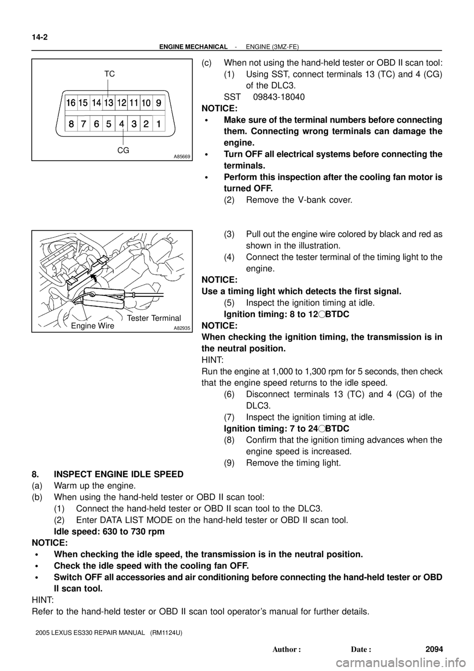
(1) Using SST, connect terminals 13 (TC) and 4 (CG)
of the DLC3.
SST 09843-18040
NOTICE:
�Make sure of the terminal numbers before connecting
them. Connecting wrong terminals can damage the
engine.
�Turn OFF all electrical systems before connecting the
terminals.
�Perform this inspection after the cooling fan motor is
turned OFF.
(2) Remove the V-bank cover.
(3) Pull out the engine wire colored by black and red as
shown in the illustration.
(4) Connect the tester terminal of the timing light to the
engine.
NOTICE:
Use a timing light which detects the first signal.
(5) Inspect the ignition timing at idle.
Ignition timing: 8 to 12� BTDC
NOTICE:
When checking the ignition timing, the transmission is in
the neutral position.
HINT:
Run the engine at 1,000 to 1,300 rpm for 5 seconds, then check
that the engine speed returns to the idle speed.
(6) Disconnect terminals 13 (TC) and 4 (CG) of the
DLC3.
(7) Inspect the ignition timing at idle.
Ignition timing: 7 to 24� BTDC
(8) Confirm that the ignition timing advances when the
engine speed is increased.
(9) Remove the timing light.
8. INSPECT ENGINE IDLE SPEED
(a) Warm up the engine.
(b) When using the hand-held tester or OBD II scan tool:
(1) Connect the hand-held tester or OBD II scan tool to the DLC3.
(2) Enter DATA LIST MODE on the hand-held tester or OBD II scan tool.
Idle speed: 630 to 730 rpm
NOTICE:
�When checking the idle speed, the transmission is in the neutral position.
�Check the idle speed with the cooling fan OFF.
�Switch OFF all accessories and air conditioning before connecting the hand-held tester or OBD
II scan tool.
HINT:
Refer to the hand-held tester or OBD II scan tool operator's manual for further details.
Page 393 of 969
A84925N´m (kgf´cm, ft´lbf)
: Specified torque
58 (591, 43)
28 (286, 21)
8.4 (85, 74 in.Vlbf)
43 (438, 32)
18 (178, 13)
18 (184, 13)
9.8 (100, 7)
64 (653, 47)
64 (653, 47)
23 (235, 17)
25 (250, 18)
V Belt No. 1
Generator Bracket No. 2
Engine Moving
Control Rod
Generator Assy
Generator Belt Adjusting BarEngine Mounting
Stay No. 2 RH
Fuel Vapor
Feed Hose No. 1
Union to Check
Valve Hose
Heater Inlet
Water Hose
Fuel Pipe
Sub-assy No. 1
Fuel Pipe Clamp No. 1
Transmission Control
Cable Assy
Heater Outlet
Water Hose
Radiator Hose Outlet
Steering Gear Outlet
Return Tube
Radiator Hose Inlet
Oil Reservoir to Pump Hose No. 1
Fan Belt Adjusting
Bar Bracket
25 (250, 18)
25 (250, 18)15 (153, 11)
Oil Cooler Inlet Hose
Oil Cooler Outlet Hose
Radio Setting
Condenser
Compressor and
Magnetic Clutch
- ENGINE MECHANICALPARTIAL ENGINE ASSY (3MZ-FE)
14-17
2109 Author�: Date�:
2005 LEXUS ES330 REPAIR MANUAL (RM1124U)
Page 405 of 969
141J9-02
A60072
- ENGINE MECHANICALPARTIAL ENGINE ASSY (3MZ-FE)
14-29
2121 Author�: Date�:
2005 LEXUS ES330 REPAIR MANUAL (RM1124U)
REPLACEMENT
1. DISCHARGE FUEL SYSTEM PRESSURE (See page 11-1)
2. DISCONNECT BATTERY NEGATIVE TERMINAL
3. REMOVE FRONT WHEELS
4. REMOVE ENGINE UNDER COVER NO.1
5. REMOVE ENGINE UNDER COVER NO.2
6. REMOVE FRONT FENDER APRON SEAL RH
7. DRAIN ENGINE COOLANT (See page 16-9)
8. DRAIN ENGINE OIL (See page 17-20)
9. DRAIN AUTOMATIC TRANSAXLE FLUID (See page 30-8)
10. REMOVE V-BANK COVER SUB-ASSY (See page 10-1 1)
11. REMOVE RADIATOR LOWER AIR DEFLECTOR (See page 19-5)
12. REMOVE BATTERY
13. REMOVE BATTERY TRAY
14. REMOVE AIR CLEANER INLET ASSY (See page 19-5)
15. REMOVE AIR CLEANER ASSY (See page 19-5)
16. REMOVE AIR CLEANER BRACKET (See page 19-5)
17. REMOVE AIR CLEANER INLET NO.1 (See page 19-5)
18. REMOVE INTAKE AIR RESONATOR SUB-ASSY
(a) Remove the clip and bolt, then remove the intake air resonator.
19. REMOVE V (COOLER COMPRESSOR TO CRANKSHAFT PULLEY) BELT NO.1
(See page 14-5)
20. REMOVE GENERATOR ASSY (See page 19-21)
21. REMOVE ENGINE MOVING CONTROL ROD (See page 14-79)
22. REMOVE ENGINE MOUNTING STAY NO.2 RH (See page 14-79)
23. REMOVE GENERATOR BRACKET NO.2 (See page 14-79)
24. REMOVE GENERATOR BELT ADJUSTING BAR (See page 17-9)
25. SEPARATE COMPRESSOR AND MAGNETIC CLUTCH (See page 17-9)
26. SEPARATE TRANSMISSION CONTROL CABLE ASSY (See page 40-44)
27. DISCONNECT UNION TO CHECK VALVE HOSE
28. DISCONNECT FUEL VAPOR FEED HOSE NO.1
29. DISCONNECT FUEL PIPE SUB-ASSY NO.1 (See page 11-1)
30. DISCONNECT HEATER INLET WATER HOSE
31. DISCONNECT HEATER OUTLET WATER HOSE
32. DISCONNECT RADIATOR HOSE INLET
33. DISCONNECT RADIATOR HOSE OUTLET
34. DISCONNECT OIL COOLER INLET HOSE
35. DISCONNECT OIL COOLER OUTLET HOSE
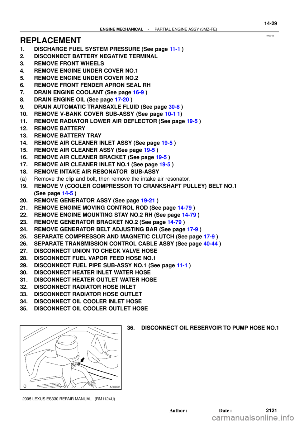
36. DISCONNECT OIL RESERVOIR TO PUMP HOSE NO.1
Page 414 of 969
A86570
From Canister
Vacuum Tank
Actuator Actuator
Vacuum Surge
TankVSV for EVAP
VSV for ACIS
Engine Mounting
Insulator FR
VSV for Active Control
Engine MountCapVSV Vacuum Hose Routing Diagram:
14-38
- ENGINE MECHANICALPARTIAL ENGINE ASSY (3MZ-FE)
2130 Author�: Date�:
2005 LEXUS ES330 REPAIR MANUAL (RM1124U)
140. CONNECT TRANSMISSION CONTROL CABLE ASSY (See page 40-44)
141. INSTALL COMPRESSOR AND MAGNETIC CLUTCH (See page 17-9)
142. INSTALL GENERATOR BELT ADJUSTING BAR (See page 17-9)
143. INSTALL GENERATOR BRACKET NO.2 (See page 14-79)
144. INSTALL ENGINE MOUNTING STAY NO.2 RH (See page 14-79)
145. INSTALL ENGINE MOVING CONTROL ROD (See page 14-79)
146. INSTALL GENERATOR ASSY (See page 19-21)
147. INSTALL V (COOLER COMPRESSOR TO CRANKSHAFT PULLEY) BELT NO.1
(See page 14-5)
148. INSPECT DRIVE BELT DEFLECTION AND TENSION (See page 14-1)
149. INSTALL INTAKE AIR RESONATOR SUB-ASSY
Torque: 5.0 NVm (51 kgfVcm, 44 in.Vlbf)
150. INSTALL AIR CLEANER INLET NO.1 (See page 19-5)
151. INSTALL AIR CLEANER BRACKET (See page 19-5)
152. INSTALL AIR CLEANER ASSY (See page 19-5)
153. INSTALL AIR CLEANER INLET ASSY (See page 19-5)
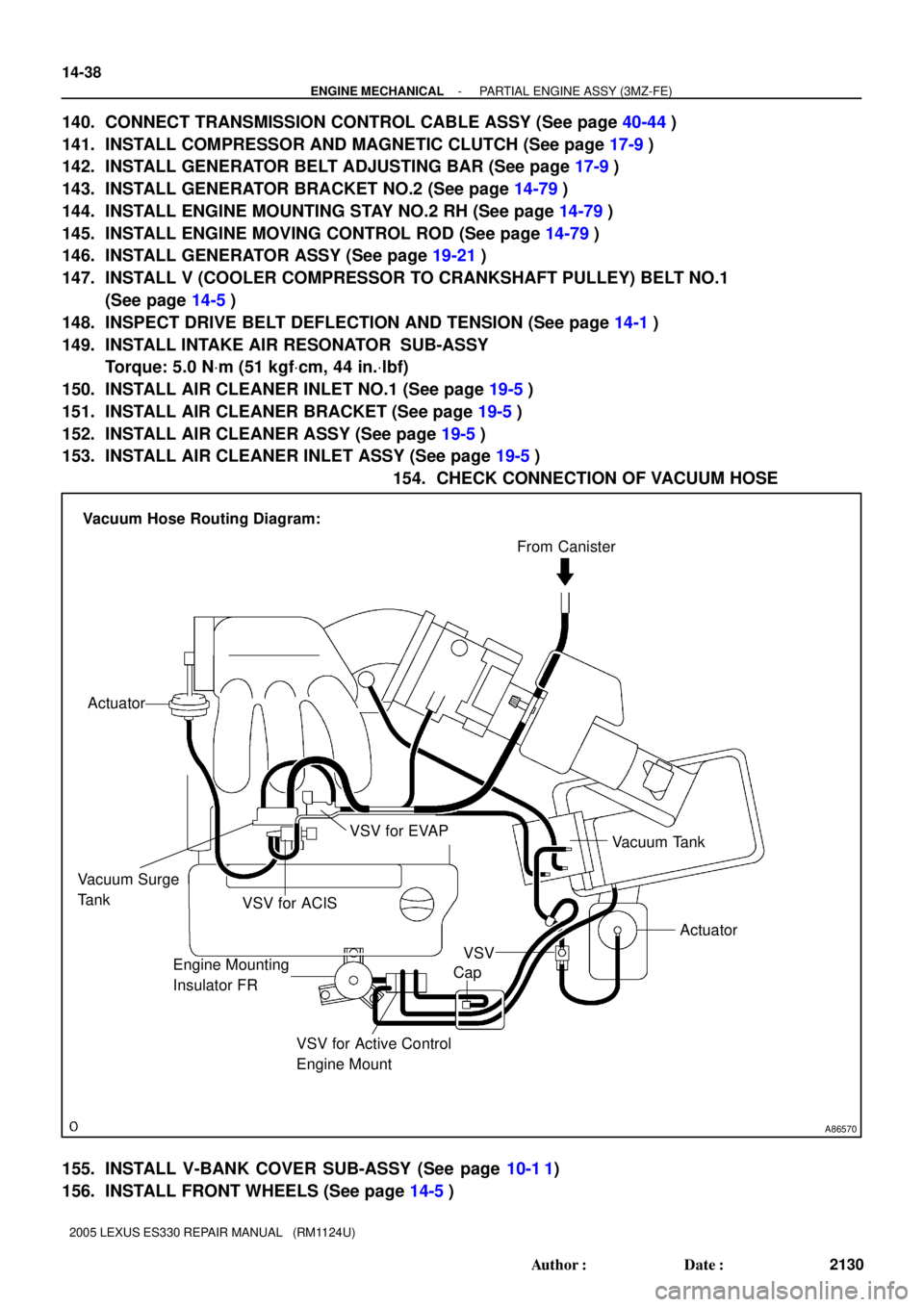
154. CHECK CONNECTION OF VACUUM HOSE
155. INSTALL V-BANK COVER SUB-ASSY (See page 10-1 1)
156. INSTALL FRONT WHEELS (See page 14-5)
Page 558 of 969
100IZ-01
A86347DLC3
Hand-held Tester
A86347DLC3
Hand-held Tester
- ENGINE CONTROL SYSTEMSFI SYSTEM (3MZ-FE)
10-1
2006 Author�: Date�:
2005 LEXUS ES330 REPAIR MANUAL (RM1124U)
SFI SYSTEM (3MZ-FE)
ON-VEHICLE INSPECTION
1. INSPECT CAMSHAFT TIMING OIL CONTROL VALVE
ASSY
(a) Check the operation.
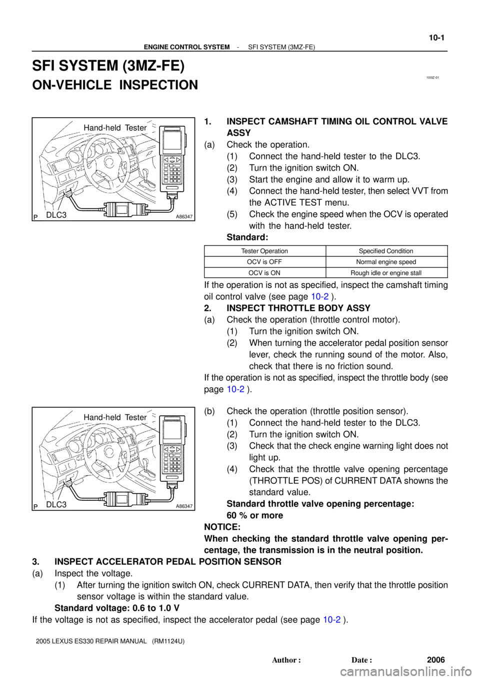
(1) Connect the hand-held tester to the DLC3.
(2) Turn the ignition switch ON.
(3) Start the engine and allow it to warm up.
(4) Connect the hand-held tester, then select VVT from
the ACTIVE TEST menu.
(5) Check the engine speed when the OCV is operated
with the hand-held tester.
Standard:
Tester OperationSpecified Condition
OCV is OFFNormal engine speed
OCV is ONRough idle or engine stall
If the operation is not as specified, inspect the camshaft timing
oil control valve (see page 10-2).
2. INSPECT THROTTLE BODY ASSY
(a) Check the operation (throttle control motor).
(1) Turn the ignition switch ON.
(2) When turning the accelerator pedal position sensor
lever, check the running sound of the motor. Also,
check that there is no friction sound.
If the operation is not as specified, inspect the throttle body (see
page 10-2).
(b) Check the operation (throttle position sensor).
(1) Connect the hand-held tester to the DLC3.
(2) Turn the ignition switch ON.
(3) Check that the check engine warning light does not
light up.
(4) Check that the throttle valve opening percentage
(THROTTLE POS) of CURRENT DATA showns the
standard value.
Standard throttle valve opening percentage:
60 % or more
NOTICE:
When checking the standard throttle valve opening per-
centage, the transmission is in the neutral position.
3. INSPECT ACCELERATOR PEDAL POSITION SENSOR
(a) Inspect the voltage.
(1) After turning the ignition switch ON, check CURRENT DATA, then verify that the throttle position
sensor voltage is within the standard value.
Standard voltage: 0.6 to 1.0 V
If the voltage is not as specified, inspect the accelerator pedal (see page 10-2).
Page 610 of 969
A86275
PinchPinch
Pull Out
A75650
Tube Connector
Pipe O-ring Nylon Tube
Quick Connector
A86276
A
A
Push
Pinch
Pinch(d)(d)
(e)
A79478
11-30
- FUELFUEL TANK ASSY (3MZ-FE)
2058 Author�: Date�:
2005 LEXUS ES330 REPAIR MANUAL (RM1124U)
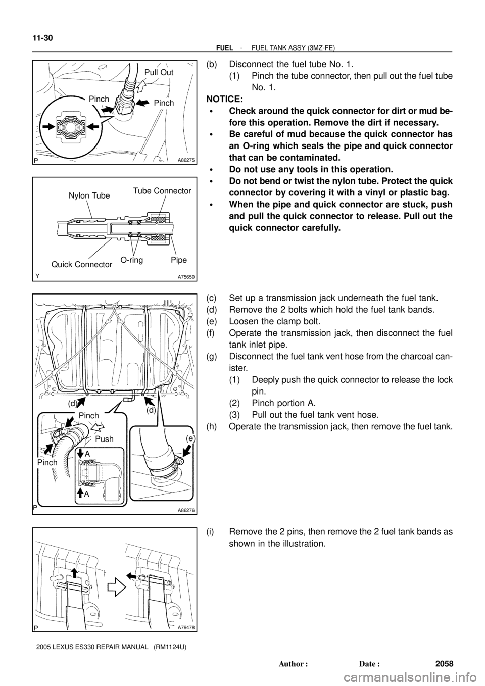
(b) Disconnect the fuel tube No. 1.
(1) Pinch the tube connector, then pull out the fuel tube
No. 1.
NOTICE:
�Check around the quick connector for dirt or mud be-
fore this operation. Remove the dirt if necessary.
�Be careful of mud because the quick connector has
an O-ring which seals the pipe and quick connector
that can be contaminated.
�Do not use any tools in this operation.
�Do not bend or twist the nylon tube. Protect the quick
connector by covering it with a vinyl or plastic bag.
�When the pipe and quick connector are stuck, push
and pull the quick connector to release. Pull out the
quick connector carefully.
(c) Set up a transmission jack underneath the fuel tank.
(d) Remove the 2 bolts which hold the fuel tank bands.
(e) Loosen the clamp bolt.
(f) Operate the transmission jack, then disconnect the fuel
tank inlet pipe.
(g) Disconnect the fuel tank vent hose from the charcoal can-
ister.
(1) Deeply push the quick connector to release the lock
pin.
(2) Pinch portion A.
(3) Pull out the fuel tank vent hose.
(h) Operate the transmission jack, then remove the fuel tank.
(i) Remove the 2 pins, then remove the 2 fuel tank bands as
shown in the illustration.