Page 353 of 969

2411 Author�: Date�:
2005 LEXUS ES330 REPAIR MANUAL (RM1124U)
FRONT DRIVE SHAFT (From")
300M5-01
C91611
SST
F40136
C83022
F40147
30-8
- DRIVE SHAFT / PROPELLER SHAFTFRONT DRIVE SHAFT (From July, 2003)
2411 Author�: Date�:
2005 LEXUS ES330 REPAIR MANUAL (RM1124U)
FRONT DRIVE SHAFT (From July, 2003)
OVERHAUL
HINT:
�COMPONENTS: See page 30-4
�Overhaul the RH side following the same procedures as for the LH side.
1. DRAIN AUTOMATIC TRANSAXLE FLUID
2. REMOVE FRONT WHEEL
3. REMOVE FRONT AXLE HUB LH NUT
(a) Using SST and a hammer, unstake the staked part of the
front axle hub LH nut.
SST 09930-00010
NOTICE:
Loosen the staked part of the lock nut completely, other-
wise the screw of the drive shaft may be damaged.
(b) While applying the brake, remove the front axle hub LH
nut.
4. DISCONNECT FRONT STABILIZER LINK ASSY LH
(a) Remove the nut, and separate the stabilizer link assy LH.
HINT:
If the ball joint turns together with the nut, use a hexagon
wrench (6 mm) to hold the stud.
5. DISCONNECT SPEED SENSOR FRONT LH
(a) Remove the bolt and clip, and separate the sensor wire
and hose from the shock absorber.
NOTICE:
Be careful not to damage the speed sensor.
(b) Remove the bolt, and separate the speed sensor front LH
from the steering knuckle.
NOTICE:
Prevent foreign matter from adhering to the speed sensor.
Page 355 of 969

2413 Author�: Date�:
2005 LEXUS ES330 REPAIR MANUAL (RM1124U)
11. FIX FRONT AXLE ASSY LH
SST")
C92143
SST
C91598
C67412
F07391
30-10
- DRIVE SHAFT / PROPELLER SHAFTFRONT DRIVE SHAFT (From July, 2003)
2413 Author�: Date�:
2005 LEXUS ES330 REPAIR MANUAL (RM1124U)
11. FIX FRONT AXLE ASSY LH
SST 09608-16042 (09608-02021, 09608-02041)
NOTICE:
The hub bearing could be damaged if it is subjected to the
vehicle's full weight, such as when moving the vehicle with
the drive shaft removed.
Therefore, if it is absolutely necessary to place the vehicle
weight on the hub bearing, first support it with SST.
12. INSPECT FRONT DRIVE SHAFT ASSY LH
NOTICE:
Move the drive shaft assy keeping it level.
(a) Check that there is no remarkable play in the radial direc-
tion of the outboard joint.
(b) Check that the inboard joint slides smoothly in the thrust
direction.
(c) Check that there is no remarkable play in the radial direc-
tion of the inboard joint.
(d) Check the boots for damage.
13. REMOVE FRONT AXLE INBOARD JOINT BOOT
CLAMP
(a) One touch type
(1) Using a screwdriver, remove the front axle inboard
joint boot LH clamp and front axle inboard joint boot
LH No.2 clamp, as shown in the illustration.
(b) Claw Engagement type
(1) Using pliers, remove the front axle inboard joint
boot LH clamp and front axle inboard joint boot LH
No.2 clamp, as shown in the illustration.
14. DISCONNECT FR AXLE INBOARD JOINT BOOT
(a) Separate the inboard joint boot from the inboard joint assy.
Page 362 of 969

30-17
2420 Author�: Date�:
2005 LEXUS ES330 REPAIR MANUAL (RM1124U)
37. INSTALL FRONT DRIVE SHAFT ASSY RH
(a)")
C66548
F40142
C83022
- DRIVE SHAFT / PROPELLER SHAFTFRONT DRIVE SHAFT (From July, 2003)
30-17
2420 Author�: Date�:
2005 LEXUS ES330 REPAIR MANUAL (RM1124U)
37. INSTALL FRONT DRIVE SHAFT ASSY RH
(a) Using a screwdriver, install a new bearing bracket hole
snap ring.
NOTICE:
Do not damage the oil seal and boot.
(b) Install the bolt.
Torque: 32 NVm (330 kgfVcm, 24 ftVlbf)
38. INSTALL FRONT AXLE ASSY LH
(a) Install the front drive shaft assy LH to the front axle assy LH.
NOTICE:
�Be careful not to damage the outboard joint boot.
�Be careful not to damage the speed sensor rotor.
39. INSTALL FRONT SUSPENSION ARM SUB- ASSY
LOWER NO.1 LH
(a) Install the lower ball joint to the front suspension arm sub-
assy lower with the bolt and nuts.
Torque: 75 NVm (765 kgfVcm, 55 ftVlbf)
40. INSTALL TIE ROD ASSY LH
(a) Install the tie rod end to the steering knuckle with the nut.
Torque: 49 NVm (500 kgfVcm, 36 ftVlbf)
(b) Install a new cotter pin.
NOTICE:
If the holes for the cotter pin are not aligned, tighten the nut up to 60� further.
41. INSTALL SPEED SENSOR FRONT LH
(a) Install the flexible hose and the speed sensor to the shock
absorber with the bolt and set the clip of sensor on
knuckle.
Torque: 19 NVm (192 kgfVcm, 14 ftVlbf)
NOTICE:
�Be careful not to damage the speed sensor.
�Do not twist the sensor wire when installing the speed
sensor.
Page 363 of 969

2421 Author�: Date�:
2005 LEXUS ES330 REPAIR MANUAL (RM1124U)
(b) Install the speed sensor to the steeri")
F40147
F40136
F40152
30-18
- DRIVE SHAFT / PROPELLER SHAFTFRONT DRIVE SHAFT (From July, 2003)
2421 Author�: Date�:
2005 LEXUS ES330 REPAIR MANUAL (RM1124U)
(b) Install the speed sensor to the steering knuckle with the
bolt.
Torque: 8.0 NVm (82 kgfVcm, 71 in.Vlbf)
NOTICE:
Prevent foreign matter from adhering to the speed sensor.
42. INSTALL FRONT STABILIZER LINK ASSY LH
(a) Install the front stabilizer link assy LH with the nut.
Torque: 74 NVm (755 kgfVcm, 55 ftVlbf)
HINT:
If the ball joint turns together with the nut, use a hexagon (6 mm)
wrench to hold the stud.
43. INSTALL FRONT AXLE HUB LH NUT
(a) Using a socket wrench (30 mm), install a new axle hub LH
nut.
Torque: 294 NVm (2,998 kgfVcm, 217 ftVlbf)
(b) Using a chisel and hammer, stake the front axle hub LH
nut.
44. INSTALL FRONT WHEEL
Torque: 103 NVm (1,050 kgfVcm, 76 ftVlbf)
45. ADD AUTOMATIC TRANSAXLE FLUID (SEE PAGE 40-1)
46. INSPECT AUTOMATIC TRANSAXLE FLUID
47. INSPECT AND ADJUST FRONT WHEEL ALIGNMENT (SEE PAGE 26-5)
48. CHECK ABS SPEED SENSOR SIGNAL
w/ VSC (SEE PAGE 05-471)
w/o VSC (SEE PAGE 05-420)
Page 367 of 969

2425 Author�: Date�:
2005 LEXUS ES330 REPAIR MANUAL (RM1124U)
18. INSTALL FRONT AXL")
C83852F45465
C97690F45054
C83023
30-22
- DRIVE SHAFT / PROPELLER SHAFTFRONT AXLE HUB SUB-ASSY LH (From July, 2003)
2425 Author�: Date�:
2005 LEXUS ES330 REPAIR MANUAL (RM1124U)
18. INSTALL FRONT AXLE HUB LH HOLE SNAP RING
(a) Using snap ring pliers, install a new front axle hub LH hole
snap ring.
19. INSTALL FRONT WHEEL BEARING DUST
DEFLECTOR NO.1 LH
(a) Using SST and a hammer, install the bearing dust deflec-
tor No.1 LH.
SST 09316- 60011 (09316- 00011, 09316- 00031),
09608-32010
HINT:
Aligh the hole for the speed sensor in the bearing dust deflector
No.1 LH with the steering knuckle.
20. INSTALL LOWER BALL JOINT ASSY FRONT LH
(a) Install the lower ball joint assy front LH and tighten the nut.
Torque: 123 NVm (1,254 kgfVcm, 90 ftVlbf)
(b) Install a new cotter pin.
NOTICE:
If the holes for the cotter pin are not aligned, tighten the nut up to 60� further.
21. INSTALL FRONT AXLE ASSY LH
(a) Install the front axle assy LH with the 2 bolts and nuts to
the shock absorber assy front LH.
Torque: 210 NVm (2,141 kgfVcm, 155 ftVlbf)
NOTICE:
�Only when reusing the bolts and nuts, apply the small
amount of engine oil to the screw part of the nuts.
�Do not excessively push out the front axle assy LH.
�Be careful not to damage the outboard joint boot.
�Be careful not to damage the speed sensor rotor.
22. INSTALL FRONT SUSPENSION ARM SUB-ASSY LOWER NO.1 LH (SEE PAGE 30-8)
23. INSTALL TIE ROD ASSY LH (SEE PAGE 30-8)
24. INSTALL FRONT DISC
Page 369 of 969
C91612
C68609
30-24
- DRIVE SHAFT / PROPELLER SHAFTFRONT AXLE HUB SUB-ASSY LH (From July, 2003)
2427 Author�: Date�:
2005 LEXUS ES330 REPAIR MANUAL (RM1124U)
31. INSTALL FRONT DISC
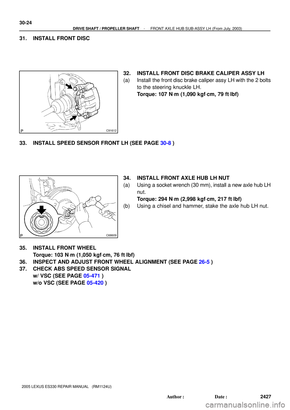
32. INSTALL FRONT DISC BRAKE CALIPER ASSY LH
(a) Install the front disc brake caliper assy LH with the 2 bolts
to the steering knuckle LH.
Torque: 107 NVm (1,090 kgfVcm, 79 ftVlbf)
33. INSTALL SPEED SENSOR FRONT LH (SEE PAGE 30-8)
34. INSTALL FRONT AXLE HUB LH NUT
(a) Using a socket wrench (30 mm), install a new axle hub LH
nut.
Torque: 294 NVm (2,998 kgfVcm, 217 ftVlbf)
(b) Using a chisel and hammer, stake the axle hub LH nut.
35. INSTALL FRONT WHEEL
Torque: 103 NVm (1,050 kgfVcm, 76 ftVlbf)
36. INSPECT AND ADJUST FRONT WHEEL ALIGNMENT (SEE PAGE
26-5)
37. CHECK ABS SPEED SENSOR SIGNAL
w/ VSC (SEE PAGE 05-471)
w/o VSC (SEE PAGE 05-420)
Page 373 of 969
C83014
30-28
- DRIVE SHAFT / PROPELLER SHAFTREAR AXLE HUB & BEARING ASSY LH
2431 Author�: Date�:
2005 LEXUS ES330 REPAIR MANUAL (RM1124U)
(b) Install the rear flexible hose with the bolt.
Torque: 19 NVm (192 kgfVcm, 14 ftVlbf)
14. INSTALL REAR WHEEL
Torque: 103 NVm (1,050 kgfVcm, 76 ftVlbf)
15. INSPECT AND ADJUST REAR WHEEL ALIGNMENT (SEE PAGE 27-3)
16. CHECK ABS SPEED SENSOR SIGNAL
w/ VSC (SEE PAGE 05-471)
w/o VSC (SEE PAGE 05-420)
Page 374 of 969

REAR AXLE CARRIER SUB-ASSY LH
REPLACEME")
3006J-06
C83017
C83018
C83019
- DRIVE SHAFT / PROPELLER SHAFTREAR AXLE CARRIER SUB-ASSY LH
30-29
2432 Author�: Date�:
2005 LEXUS ES330 REPAIR MANUAL (RM1124U)
REAR AXLE CARRIER SUB-ASSY LH
REPLACEMENT
HINT:
�COMPONENTS: See page 30-4
�Replace the RH side by the same procedures with the LH side.
1. REMOVE REAR WHEEL
2. REMOVE STRUT ROD ASSY REAR (SEE PAGE 27-18)
3. DISCONNECT REAR DISC BRAKE CALIPER ASSY LH (SEE PAGE 30-26)
4. REMOVE REAR DISC
5. DISCONNECT SKID CONTROL SENSOR WIRE
6. REMOVE REAR AXLE HUB & BEARING ASSY LH (SEE PAGE 30-26)
7. SEPARATE REAR SUSPENSION ARM ASSY NO.2 LH
(a) Remove the bolt, nut and rear suspension arm assy No.2
LH from the rear axle carrier sub-assy LH.
HINT:
While fixing the nut, turn and remove the bolt.
8. SEPARATE REAR SUSPENSION ARM ASSY NO.1 LH
(a) Remove the bolt, nut and rear suspension arm assy No.1
LH from the rear axle carrier sub-assy LH.
HINT:
While fixing the nut, turn and remove the bolt.
9. REMOVE REAR AXLE CARRIER SUB-ASSY LH
(a) Remove the 2 bolts, nuts and rear axle carrier sub-assy
LH from the shock absorber assy rear LH.
NOTICE:
When removing bolt, stop the bolt from rotating and loosen
the nut.