Page 2479 of 3419

LT-32
HEADLAMP (FOR USA)
Revision: October 20052005 QX56
Installation is in the reverse order of removal.
CAUTION:
�After installing the bulb, be sure to install the bulb socket securely to ensure watertightness.
�Do not touch the glass of bulb directly by hand. Keep grease and other oily substances away from
it. Do not touch bulb by hand while it is lit or right after being turned off. Burning may result.
�Do not leave bulb out of headlamp assembly for a long time because dust, moisture, smoke, etc.
may affect the performance of the lamp. When replacing bulb, be sure to replace it with a new one.
Removal and InstallationEKS00B8B
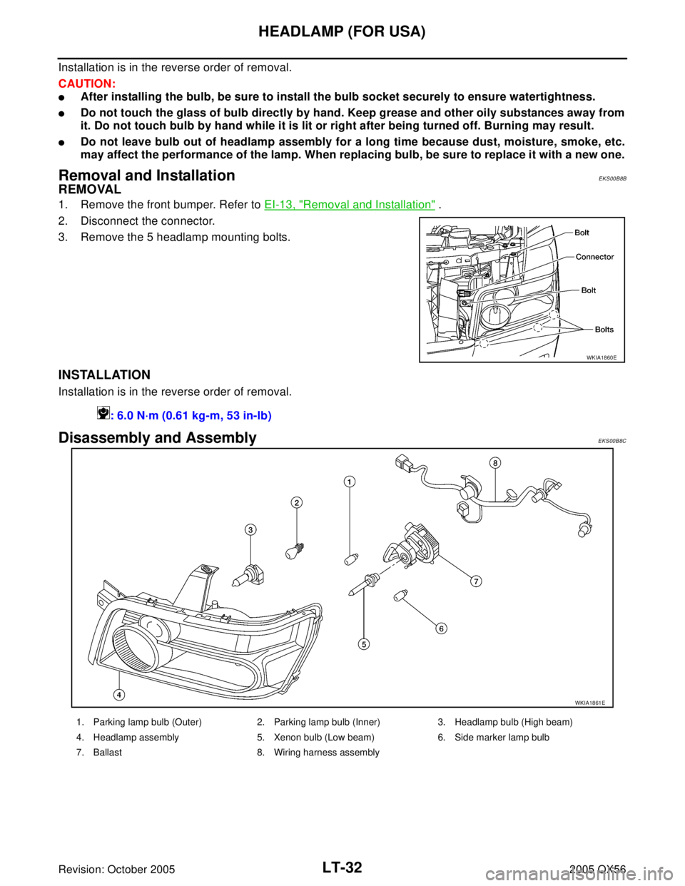
REMOVAL
1. Remove the front bumper. Refer to EI-13, "Removal and Installation" .
2. Disconnect the connector.
3. Remove the 5 headlamp mounting bolts.
INSTALLATION
Installation is in the reverse order of removal.
Disassembly and AssemblyEKS00B8C
WKIA1860E
: 6.0 N·m (0.61 kg-m, 53 in-lb)
WKIA1861E
1. Parking lamp bulb (Outer) 2. Parking lamp bulb (Inner) 3. Headlamp bulb (High beam)
4. Headlamp assembly 5. Xenon bulb (Low beam) 6. Side marker lamp bulb
7. Ballast 8. Wiring harness assembly
Page 2480 of 3419
HEADLAMP (FOR CANADA) - DAYTIME LIGHT SYSTEM -
LT-33
C
D
E
F
G
H
I
J
L
MA
B
LT
Revision: October 20052005 QX56
HEADLAMP (FOR CANADA) - DAYTIME LIGHT SYSTEM -PFP:26010
Component Parts and Harness Connector LocationEKS00B8D
WKIA3551E
Page 2481 of 3419

LT-34
HEADLAMP (FOR CANADA) - DAYTIME LIGHT SYSTEM -
Revision: October 20052005 QX56
System DescriptionEKS00B8E
Daytime light system turns on daytime light lamps while driving. Daytime light lamps are not turned on if
engine is activated with parking brake applied. Release parking brake to turn on daytime light lamps. The
lamps turn off when lighting switch is in the 2ND position or AUTO position (Headlamp is "ON") and when light-
ing switch is in the PASSING position. (Daytime light lamps are not turned off only by parking brake itself.)
A parking brake signal and engine run or stop signal are sent to BCM (body control module) by CAN commu-
nication line.
OUTLINE
Power is supplied at all times
�to ignition relay, located in the IPDM E/R (intelligent power distribution module engine room), and
�through 50A fusible link (letter f , located in the fuse and fusible link box)
�to BCM terminal 70, and
�through 20A fuse (No. 53, located in the IPDM E/R)
�to CPU (central processing unit) of the IPDM E/R, and
�through 10A fuse [No. 19, located in the fuse block (J/B)]
�to combination meter terminal 8, and
�through 10A fuse (No. 45, located in the IPDM E/R)
�to daytime light relay terminals 2 and 5.
When the ignition switch is in ON or START position, power is supplied
�to ignition relay, located in the IPDM E/R, and
�through 10A fuse (No. 59, located in the fuse and relay box)
�to BCM terminal 38, and
�through 10A fuse [No. 14, located in the fuse block (J/B)]
�to combination meter terminal 24.
Ground is supplied
�to BCM terminal 67 and
�to combination meter terminal 17
�through grounds M57, M61 and M79.
DAYTIME LIGHT OPERATION
With the engine running, the lighting switch in the OFF or 1ST position and parking brake released, the IPDM
E/R receives input requesting the daytime lights illuminate. This input is communicated across the CAN com-
munication lines. The CPU of the IPDM E/R controls the daytime light relay coil. When energized, this relay
directs power
�through daytime light relay terminal 3
�to front combination lamp LH terminal 2
�through front combination lamp LH terminal 6
�to IPDM E/R terminal 55
�through 10A fuse (No. 35, located in the IPDM E/R)
�through 10A fuse (No. 34, located in the IPDM E/R)
�through IPDM E/R terminal 56
�to front combination lamp RH terminal 6.
Ground is supplied
�to front combination lamp RH terminal 2
�through grounds E9, E15 and E24.
With power and ground supplied, the daytime lights illuminate. The high beam headlamps are now wired in
series and illuminate at a reduced intensity.
COMBINATION SWITCH READING FUNCTION
Refer to BCS-3, "COMBINATION SWITCH READING FUNCTION" .
Page 2482 of 3419
HEADLAMP (FOR CANADA) - DAYTIME LIGHT SYSTEM -
LT-35
C
D
E
F
G
H
I
J
L
MA
B
LT
Revision: October 20052005 QX56
AUTO LIGHT OPERATION
For auto light operation, refer to LT-4 8, "System Description" in AUTO LIGHT SYSTEM.
CAN Communication System DescriptionEKS00B8F
Refer to LAN-5, "CAN COMMUNICATION" .
Page 2483 of 3419
LT-36
HEADLAMP (FOR CANADA) - DAYTIME LIGHT SYSTEM -
Revision: October 20052005 QX56
SchematicEKS00B8G
WKWA2483E
Page 2484 of 3419
HEADLAMP (FOR CANADA) - DAYTIME LIGHT SYSTEM -
LT-37
C
D
E
F
G
H
I
J
L
MA
B
LT
Revision: October 20052005 QX56
Wiring Diagram — DTRL —EKS00B8H
WKWA2398E
Page 2485 of 3419
LT-38
HEADLAMP (FOR CANADA) - DAYTIME LIGHT SYSTEM -
Revision: October 20052005 QX56
WKWA2399E
Page 2486 of 3419
HEADLAMP (FOR CANADA) - DAYTIME LIGHT SYSTEM -
LT-39
C
D
E
F
G
H
I
J
L
MA
B
LT
Revision: October 20052005 QX56
WKWA2400E