Page 2455 of 3419
LT-8
HEADLAMP (FOR USA)
Revision: October 20052005 QX56
�Power consumption is approximately 25 percent less than halogen headlamps, reducing battery load.
BATTERY SAVER CONTROL
When the combination switch (lighting switch) is in the 2ND position (ON), and the ignition switch is turned
from ON or ACC to OFF, the battery saver control feature is activated.
Under this condition, the headlamps remain illuminated for 5 minutes, unless the combination switch (lighting
switch) position is changed. If the combination switch (lighting switch) position is changed, then the headlamps
are turned off.
AUTO LIGHT OPERATION
Refer to LT- 4 8 , "System Description" for auto light operation.
VEHICLE SECURITY SYSTEM (PANIC ALARM)
The vehicle security system (panic alarm) will flash the high beams if the system is triggered. Refer to BL-48,
"Panic Alarm Operation" .
CAN Communication System DescriptionEKS00B7U
Refer to LAN-5, "CAN COMMUNICATION" .
Page 2456 of 3419
HEADLAMP (FOR USA)
LT-9
C
D
E
F
G
H
I
J
L
MA
B
LT
Revision: October 20052005 QX56
SchematicEKS00B7V
WKWA1192E
Page 2457 of 3419
LT-10
HEADLAMP (FOR USA)
Revision: October 20052005 QX56
Wiring Diagram — H/LAMP —EKS00B7W
WKWA2394E
Page 2458 of 3419
HEADLAMP (FOR USA)
LT-11
C
D
E
F
G
H
I
J
L
MA
B
LT
Revision: October 20052005 QX56
WKWA2395E
Page 2459 of 3419
LT-12
HEADLAMP (FOR USA)
Revision: October 20052005 QX56
WKWA2482E
Page 2460 of 3419
HEADLAMP (FOR USA)
LT-13
C
D
E
F
G
H
I
J
L
MA
B
LT
Revision: October 20052005 QX56
WKWA2396E
Page 2461 of 3419
LT-14
HEADLAMP (FOR USA)
Revision: October 20052005 QX56
Terminals and Reference Values for BCMEKS00B7X
Terminal
No.Wire
colorSignal nameMeasuring condition
Reference value
(Approx.) Ignition
switchOperation or condition
2 SB Combination switch input 5 ONLighting, turn, wiper OFF
Wiper dial position 4
3 G/Y Combination switch input 4 ONLighting, turn, wiper OFF
Wiper dial position 4
4 Y Combination switch input 3 ONLighting, turn, wiper OFF
Wiper dial position 4
5 G/B Combination switch input 2
ONLighting, turn, wiper OFF
Wiper dial position 4
6 V Combination switch input 1
32 R/G Combination switch output 5 ONLighting, turn, wiper OFF
Wiper dial position 4
33 R/Y Combination switch output 4 ONLighting, turn, wiper OFF
Wiper dial position 4
34 L Combination switch output 3 ONLighting, turn, wiper OFF
Wiper dial position 4
SKIA5291E
SKIA5292E
SKIA5291E
SKIA5292E
SKIA5291E
SKIA5292E
SKIA5291E
Page 2462 of 3419

HEADLAMP (FOR USA)
LT-15
C
D
E
F
G
H
I
J
L
MA
B
LT
Revision: October 20052005 QX56
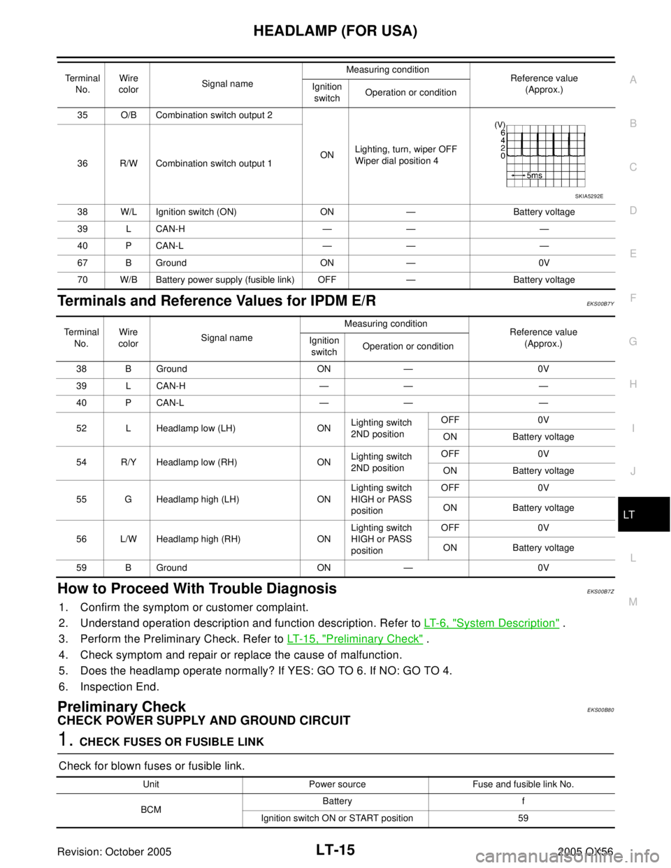
Terminals and Reference Values for IPDM E/REKS00B7Y
How to Proceed With Trouble DiagnosisEKS00B7Z
1. Confirm the symptom or customer complaint.
2. Understand operation description and function description. Refer to LT- 6 , "
System Description" .
3. Perform the Preliminary Check. Refer to LT- 1 5 , "
Preliminary Check" .
4. Check symptom and repair or replace the cause of malfunction.
5. Does the headlamp operate normally? If YES: GO TO 6. If NO: GO TO 4.
6. Inspection End.
Preliminary CheckEKS00B80
CHECK POWER SUPPLY AND GROUND CIRCUIT
1. CHECK FUSES OR FUSIBLE LINK
Check for blown fuses or fusible link.
35 O/B Combination switch output 2
ONLighting, turn, wiper OFF
Wiper dial position 4
36 R/W Combination switch output 1
38 W/L Ignition switch (ON) ON — Battery voltage
39 L CAN-H — — —
40 P CAN-L — — —
67 B Ground ON — 0V
70 W/B Battery power supply (fusible link) OFF — Battery voltage Terminal
No.Wire
colorSignal nameMeasuring condition
Reference value
(Approx.) Ignition
switchOperation or condition
SKIA5292E
Te r m i n a l
No.Wire
colorSignal nameMeasuring condition
Reference value
(Approx.) Ignition
switchOperation or condition
38 B Ground ON — 0V
39 L CAN-H — — —
40 P CAN-L — — —
52 L Headlamp low (LH) ONLighting switch
2ND positionOFF 0V
ON Battery voltage
54 R/Y Headlamp low (RH) ONLighting switch
2ND positionOFF 0V
ON Battery voltage
55 G Headlamp high (LH) ONLighting switch
HIGH or PASS
positionOFF 0V
ON Battery voltage
56 L/W Headlamp high (RH) ONLighting switch
HIGH or PASS
positionOFF 0V
ON Battery voltage
59 B Ground ON — 0V
Unit Power source Fuse and fusible link No.
BCMBattery f
Ignition switch ON or START position 59