Page 301 of 3419
AT-230
ON-VEHICLE SERVICE
Revision: October 20052005 QX56
2. Install the oil pan and new oil pan gasket.
CAUTION:
�Be sure the oil pan drain plug is located to the rear of the
transmission assembly.
�Before installing oil pan bolts, remove any traces of old
sealant from the sealing surfaces and threaded holes.
�Do not reuse old gasket, replace with a new one.
�Always replace the oil pan bolts as they are self-sealing.
�Partially install the oil pan bolts in a criss-cross pattern to
prevent dislocation of the gasket.
3. Tighten oil pan bolts in numerical order as shown.
4. Install drain plug in oil pan.
CAUTION:
Do not reuse old drain plug gasket replace with a new one.
5. Refill the transmission assembly with fluid. Refer to MA-24, "
Changing A/T Fluid" .
SCIA2308E
Oil pan bolts : 7.9 N·m (0.81 kg-m, 70 in-lb)
SCIA4 113 E
Drain plug : 34 N·m (3.5 kg-m, 25 ft-lb)
Page 2060 of 3419
FRONT FINAL DRIVE ASSEMBLY
FFD-29
C
E
F
G
H
I
J
K
L
MA
B
FFD
Revision: October 20052005 QX56
4. Install pinion mate shaft to differential case so that it meets lock
pin holes.
5. Measure side gear end play. If necessary, select the appropriate
side gear thrust washers. Refer to FFD-23, "
Differential Side
Gear Clearance" .
6. Drive a lock pin into pinion mate shaft, using a suitable punch.
Make sure lock pin is flush with differential case.
CAUTION:
Do not reuse lock pin.
7. Apply gear oil to gear tooth surfaces and thrust surfaces and
check to see they turn properly.
8. Install differential case assembly on drive gear.
�Tighten bolts in a crisscross pattern, lightly tapping bolt head
with a hammer.
9. Place differential case on drive gear. Tighten bolts in a criss-
cross fashion.
10. Press-fit side bearing inner race on differential case using Tools.
SDIA0195J
SPD0 30
SPD3 22
SDIA2239E
Tool number A: KV38100300
B: ST33081000
SDIA2240E
Page 2864 of 3419
REAR FINAL DRIVE ASSEMBLY
RFD-17
C
E
F
G
H
I
J
K
L
MA
B
RFD
Revision: October 20052005 QX56
DISASSEMBLY OF DIFFERENTIAL CASE ASSEMBLY
1. Remove the side bearing inner races using Tools.
CAUTION:
To prevent damage to the bearing, engage the puller jaws in
the groove.
�Do not to mix the left and right side parts, clearly label the
parts during disassembly.
2. Loosen the drive gear bolts in a criss-cross pattern and remove
the bolts.
3. Tap the drive gear off the differential case using a soft hammer.
�Tap evenly all around the drive gear to keep the drive gear
from binding.Tool number A: ST3306S001
B: ST33061000
SPD9 20
SPD0 22
SPD0 24
Page 2867 of 3419

RFD-20
REAR FINAL DRIVE ASSEMBLY
Revision: October 20052005 QX56
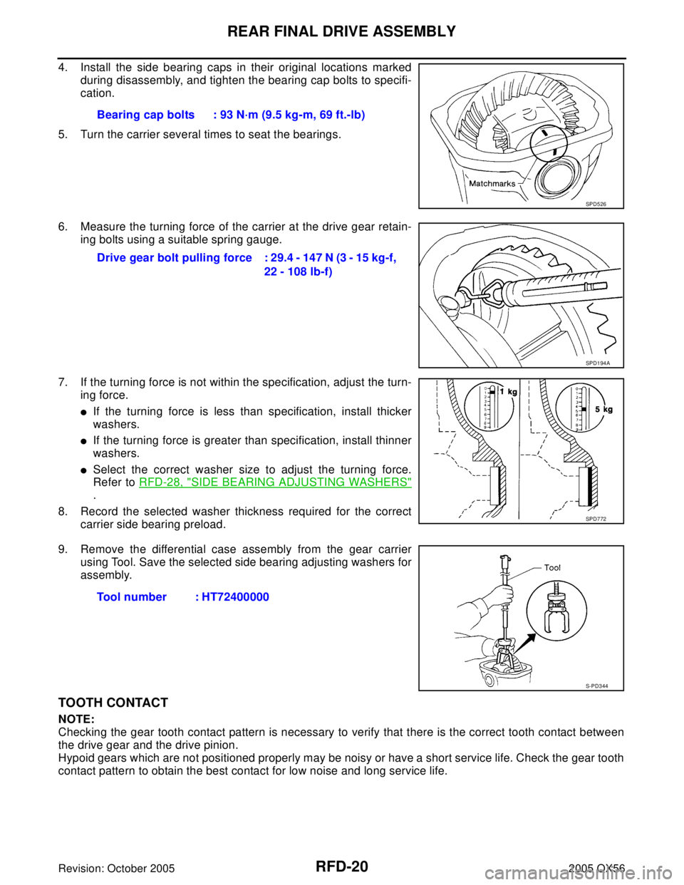
4. Install the side bearing caps in their original locations marked
during disassembly, and tighten the bearing cap bolts to specifi-
cation.
5. Turn the carrier several times to seat the bearings.
6. Measure the turning force of the carrier at the drive gear retain-
ing bolts using a suitable spring gauge.
7. If the turning force is not within the specification, adjust the turn-
ing force.
�If the turning force is less than specification, install thicker
washers.
�If the turning force is greater than specification, install thinner
washers.
�Select the correct washer size to adjust the turning force.
Refer to RFD-28, "
SIDE BEARING ADJUSTING WASHERS"
.
8. Record the selected washer thickness required for the correct
carrier side bearing preload.
9. Remove the differential case assembly from the gear carrier
using Tool. Save the selected side bearing adjusting washers for
assembly.
TOOTH CONTACT
NOTE:
Checking the gear tooth contact pattern is necessary to verify that there is the correct tooth contact between
the drive gear and the drive pinion.
Hypoid gears which are not positioned properly may be noisy or have a short service life. Check the gear tooth
contact pattern to obtain the best contact for low noise and long service life.Bearing cap bolts : 93 N·m (9.5 kg-m, 69 ft.-lb)
SPD5 26
Drive gear bolt pulling force : 29.4 - 147 N (3 - 15 kg-f,
22 - 108 lb-f)
SPD1 94 A
SPD7 72
Tool number : HT72400000
S-PD3 44
Page 2869 of 3419
RFD-22
REAR FINAL DRIVE ASSEMBLY
Revision: October 20052005 QX56
3. Apply genuine medium strength locking sealant or equivalent as
shown. Refer to GI-45, "
Recommended Chemical Products and
Sealants" .
�Tighten the drive gear bolts in a criss-cross pattern to specifi-
cation.
4. Press-fit the side bearing inner races on the differential case
using Tools.
INSTALLATION OF DRIVE PINION ASSEMBLY
1. Press-fit the pinion front and rear bearing outer races using
Tools.
2. Select pinion height adjusting washer. Refer to RFD-27, "
Drive Pinion Height Adjustment" . Drive gear bolts
Step 1 : 78.5 N·m (8.0 kg-m, 58 ft-lb)
Step 2 : 34° degrees
SPD5 54
Tool number A: KV38100200
B: ST33081000
SPD3 53
Tool number A: ST15310000
B: ST35325000
C: ST30621000
SPD9 92