Page 2787 of 3419

PS-20
POWER STEERING GEAR AND LINKAGE
Revision: October 20052005 QX56
INSPECTION AFTER DISASSEMBLY
Boot
Check boot for cracks and deformation. Replace if necessary.
Rack Assembly
Check rack gear for damage and wear. Replace if necessary.
Sub-Gear Assembly
�Check pinion gear for damage and wear. Replace if necessary.
�Check bearing while rotating it. Replace bearing if bearing ball race was dented, worn, or damaged.
Gear Housing Assembly
Check gear housing assembly for damage and scratches (inner wall). Replace if necessary.
Outer Socket and Inner Socket Swing Torque
Hook a spring balance at the point shown in the figure. Confirm if the
reading is within the specification. When ball stud and inner socket
start moving the measured value must be within the specification. If
the reading is outside the specification, replace socket.
Outer Socket and Inner Socket Rotating Torque
Using Tool, check if reading is within the value specified below. If the
value is outside the standard, replace outer sockets.
Outer Socket and Inner Socket Axial End Play
Apply load of 490 N (50 kg, 110 lb) to ball stud axially. Use a dial
gauge to measure the amount of the movement that the stud makes.
Check if the reading is within specification. If the value is outside
specification, replace outer and inner sockets.
SGIA0547E
Item Outer socket Inner socket
Measuring point Cotter pin hole of stud Shown as "L": 83.2 mm (3.276 in)
Swing torque 0.3 − 2.9 N·m (0.03 − 0.29 kg-m, 3 − 25 in-lb) 1.0 − 7.8 N·m (0.11 − 0.79 kg-m, 9 − 69 in-lb)
Measuring value 4.84 − 46.7 N (0.50 − 4.7 kg, 4 - 34 lb) 12.1 − 93.7 N (1.3 − 9.5 kg, 9 − 69 lb)
Tool number : ST3127S000 (J-25765-A)
Rotating torque : 0.3 − 2.9 N·m (0.03 − 0.29 kg-m,
3 − 25 in-lb)
SST 8 82 B
Outer socket : 0.5 mm (0.020 in) or less
Inner socket : 0.2 mm (0.008 in) or less
SGIA0057E
Page 2790 of 3419

POWER STEERING GEAR AND LINKAGE
PS-23
C
D
E
F
H
I
J
K
L
MA
B
PS
Revision: October 20052005 QX56
6. After tightening end cover assembly, caulk cylinder at one point
as shown using a punch. This will prevent end cover from get-
ting loose.
7. Install sub-gear assembly to gear housing assembly.
CAUTION:
Oil seal may be damaged if sub-gear assembly is not installed correctly.
8. Apply Genuine NISSAN PSF or equivalent to O-ring. Refer to MA-11, "
RECOMMENDED FLUIDS AND
LUBRICANTS" . Then install O-ring to rear cover.
NOTE:
Do not reuse O-ring.
9. Install rear cover to gear housing assembly using Tool.
10. Make sure projection on rear cover cap aligns with mark on gear housing assembly.
11. Apply thread locking sealant (Refer to GI-45, "
RECOMMENDED
CHEMICAL PRODUCTS AND SEALANTS" ) to the thread of
the adjusting screw. Then set adjusting screw height from gear
housing assembly. The adjusting screw height is the same as it
was measured previously.
12. Rotate pinion ten times through entire rack range to seat gears and to check operation.
13. With steering gear in neutral position, measure pinion rotating
torque using Tool from within –180° to +180°, while applying and
holding maximum torque to pinion gear.
14. After loosening adjusting screw once, tighten it again with torque of 5.4 N·m (0.55 kg-m, 48 in-lb). Then
loosen it within 20° – 40°.
SGIA0158E
Tool number : — (J-46213)
SGIA0568E
Tool number : ST3127S000 (J25765-A),
KV48103400 ( — )
SGIA0483E
Page 2791 of 3419

PS-24
POWER STEERING GEAR AND LINKAGE
Revision: October 20052005 QX56
15. Measure pinion rotating torque using Tool, then confirm whether
the reading is within the specified value. If the reading is not
within the specified value, readjust screw angle with adjusting
screw. If the reading is still not within the specified value or the
rotating torque of adjusting screw is less than 5 N·m (0.51 kg-m,
44 in-lb), replace the steering gear assembly.
16. Turn pinion to the full left lock position with inner socket to gear housing assembly.
17. Mount dial gauge to rack as shown. Measure vertical movement
of rack when pinion is turned counterclockwise with torque of
19.6 N·m (2.0 kg-m, 14 ft-lb). Check if reading is within the spec-
ified value. If reading is outside of the specification, readjust
screw angle with adjusting screw. If reading is still outside of
specification, or if the rotating torque of adjusting screw is less
than 5 N·m (0.51 kg-m, 44 in-lb), replace the steering gear
assembly.
18. Install large-diameter side of boot to gear housing assembly.
19. Install small-diameter side of boot to the mounting groove of
inner socket boot.
20. Install boot clamp to the small-diameter side of boot.Pinion rotating torque:
Around neutral position (within ±100°)
Average “A”:
0.8 − 2.0 N·m (0.09 − 0.20 kg-m, 7 − 17 in-lb)
Other than above (more than ±100°)
Maximum variation “B”:
2.3 N·m (0.23 kg-m, 20 in-lb)
SGIA0160E
SGIA0484E
Amount of vertical movement with rack Less than 0.265 mm (0.010 in)
Measuring pointAxial direction of rack5 mm (0.197 in) away from end of
gear housing
Radius direction of rack Shaft direction of adjusting screw
SGIA0550E
Page 2792 of 3419
POWER STEERING GEAR AND LINKAGE
PS-25
C
D
E
F
H
I
J
K
L
MA
B
PS
Revision: October 20052005 QX56
21. Install new boot clamps and crimp securely.
CAUTION:
Do not reuse boot clamps.
22. Install cylinder tubes to gear housing assembly.
23. Install lock nut and outer socket to inner socket.
24. Tighten lightly tie-rod in specified length “L”, then tighten lock nut
at specified torque. Refer to PS-17, "
Disassembly and Assem-
bly" . Reconfirm if tie-rod length is within limit of specified length
“L”.
CAUTION:
Perform toe-in adjustment after this procedure. Length
achieved after toe-in adjustment is not necessarily the
value given here.
AST 1 39
Inner socket length “L” : 115.2 mm (4.54 in)
SGIA0167E
Page 2793 of 3419

PS-26
POWER STEERING OIL PUMP
Revision: October 20052005 QX56
POWER STEERING OIL PUMPPFP:49110
On-Vehicle Inspection and ServiceEGS000UJ
CHECKING RELIEF OIL PRESSURE
CAUTION:
Before starting work, confirm belt tension is proper.
1. Connect Tool between oil pump discharge connector and high
pressure hose and then bleed air from the hydraulic circuit.
2. Start engine. Allow engine to run until tank temperature reaches 50 – 80°C (122 – 176°F).
CAUTION:
�Warm up engine with shut-off valve fully opened. If engine is started with shut-off valve closed,
fluid pressure in power steering pump increases to maximum. This will raise fluid temperature
excessively.
�Be careful not to contact hose with belt when engine is started.
3. With engine at idle, close shut-off valve and read the relief oil pressure.
CAUTION:
Do not close shut-off valve of pressure gauge for more than 10 seconds.
4. After measurement, open shut-off valve slowly.
�If relief oil pressure is outside the specification, disassemble and repair oil pump. Refer to PS-17, "Dis-
assembly and Assembly" .
5. After inspection, disconnect oil pressure gauge and oil pressure gauge adapter from hydraulic circuit, con-
nect oil pump discharge connector and high pressure hose. Add fluid and bleed air from hydraulic circuit
thoroughly. Refer to PS-6, "
Air Bleeding Hydraulic System" .
Removal and InstallationEGS000UK
REMOVAL
1. Drain power steering fluid from reservoir tank.
2. Remove engine room cover. Refer to EM-11, "
Removal and Installation" .
3. Remove air duct assembly. Refer to EM-14, "
Removal and Installation" .
4. Remove power steering reservoir tank.
5. Remove serpentine drive belt belt from auto tensioner and power steering pump. Refer to EM-12,
"Removal and Installation" .
6. Disconnect pressure sensor electrical connector.
7. Remove high pressure and low pressure piping from power steering oil pump. Refer to PS-31, "
HYDRAU-
LIC LINE" .
8. Remove mounting bolts, then remove power steering pump.
INSTALLATION
Installation is in the reverse order of removal. Refer to PS-31, "HYDRAULIC LINE" for tightening torque.
�After installation, bleed air. Refer to PS-6, "Air Bleeding Hydraulic System" .
NOTE:
Belt tension is automatic and requires no adjustment.
Tool number:
Pressure gauge and shut-off valveKV48103500
(J26357 and J26357-10)
Oil pump sideConnector A and
O-ringKV48105300-4 and 5295262U10
(—)
Eye-bolt and O-ringKV48105300-3 and 5295262U00
(—)
High pressure
piping sideConnector B and
O-ringKV48105300-1 and 5295262U00
(—)
NutKV48105300-2
( — )
Relief oil pressure
: 9.0 – 9.8 mPa (91.77 – 99.93 kg/cm2 , 1305.34 – 1421.37 psi)
SGIA0570E
Page 2797 of 3419
PS-30
POWER STEERING OIL PUMP
Revision: October 20052005 QX56
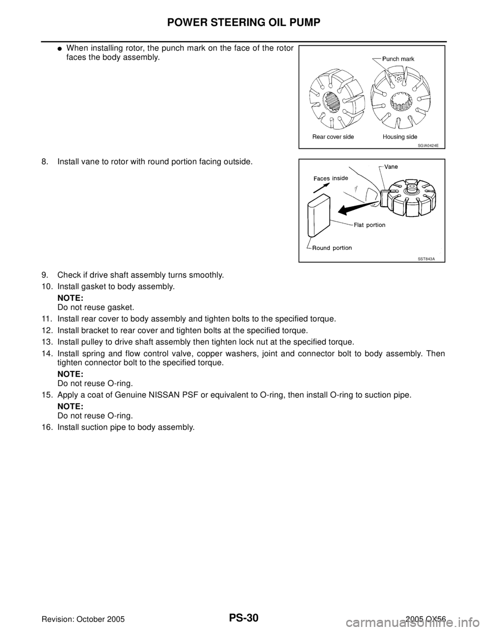
�When installing rotor, the punch mark on the face of the rotor
faces the body assembly.
8. Install vane to rotor with round portion facing outside.
9. Check if drive shaft assembly turns smoothly.
10. Install gasket to body assembly.
NOTE:
Do not reuse gasket.
11. Install rear cover to body assembly and tighten bolts to the specified torque.
12. Install bracket to rear cover and tighten bolts at the specified torque.
13. Install pulley to drive shaft assembly then tighten lock nut at the specified torque.
14. Install spring and flow control valve, copper washers, joint and connector bolt to body assembly. Then
tighten connector bolt to the specified torque.
NOTE:
Do not reuse O-ring.
15. Apply a coat of Genuine NISSAN PSF or equivalent to O-ring, then install O-ring to suction pipe.
NOTE:
Do not reuse O-ring.
16. Install suction pipe to body assembly.
SGIA0424E
SST 8 43 A
Page 2799 of 3419
PS-32
HYDRAULIC LINE
Revision: October 20052005 QX56
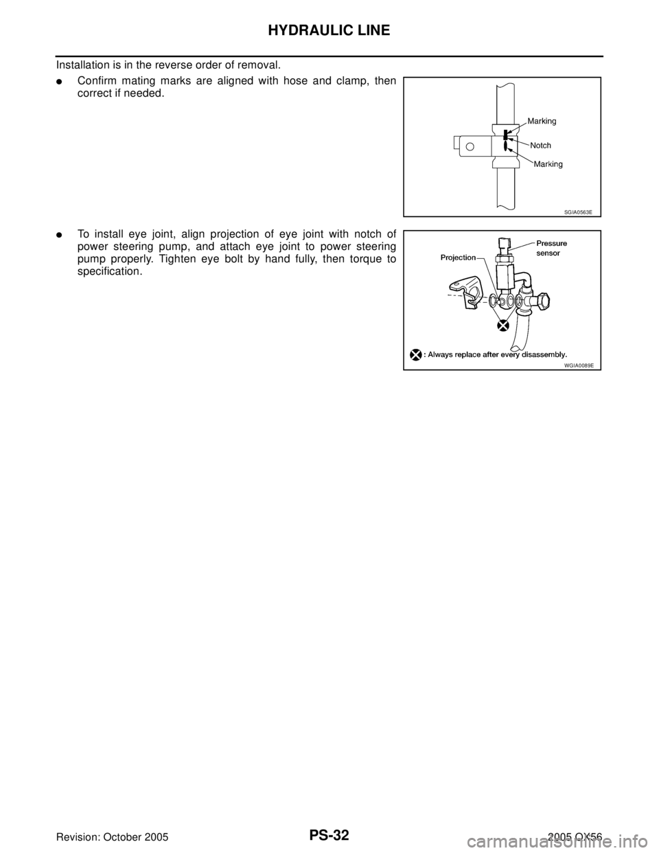
Installation is in the reverse order of removal.
�Confirm mating marks are aligned with hose and clamp, then
correct if needed.
�To install eye joint, align projection of eye joint with notch of
power steering pump, and attach eye joint to power steering
pump properly. Tighten eye bolt by hand fully, then torque to
specification.
SGIA0563E
WGIA0089E
Page 2801 of 3419
PS-34
SERVICE DATA AND SPECIFICATIONS (SDS)
Revision: October 20052005 QX56
Inspection After Installation
Steering Outer Socket and Inner SocketEGS000UP
Unit: mm (in) Range “A”61.3 mm (2.41 in)
Tilt mechanism range (Manual tilt) 3° per notch at 5 steps
WGIA0083E
Tie-rod ball joint outer socketSwinging torque 0.3 − 2.9 N·m (0.03 − 0.29 kg-m, 3 − 25 in-lb)
Measurement on spring balance�Measuring point: cotter pin hole of stud4.84 − 46.7 N (0.50 − 4.7 kg, 4 − 34 lb)
Rotating torque 0.3 − 2.9 N·m (0.03 − 0.29 kg-m, 3 − 25 in-lb)
Axial end play 0.5 mm (0.020 in) or less
Tie-rod ball joint inner socketSwinging torque 1.0 − 7.8 N·m (0.11 − 0.79 kg-m, 9 − 69 in-lb)
Measurement on spring balance
�Measuring point: "L" mark see above,
"L"=83.2 mm (3.276 in).12.1 − 93.7 N (1.3 − 9.5 kg, 9 − 69 lb)
Axial end play 0.2 mm (0.08 in) or less
SGIA0358E
Inner socket length “L” 115.2 (4.54)
SGIA0167E


Revision: October 20052005 QX56
Inspection After Installation
Steering Outer Socket and Inner SocketEGS000UP
Unit: mm (in) Range “A”61.3 mm (2.41 in)
Ti")