Page 3283 of 3419

TF-140
TRANSFER MOTOR
Revision: October 20052005 QX56
TRANSFER MOTORPFP:00000
Removal and InstallationEDS002IY
REMOVAL
1. Disconnect the transfer motor connector.
2. Remove the air breather hose from the transfer motor. Refer to
TF-139, "
Removal and Installation" .
3. Remove the transfer motor bolts.
4. Remove the transfer motor.
INSTALLATION
1. Apply ATF to the O-ring and install it to the transfer motor.
CAUTION:
Do not reuse O-rings.
2. Fit the double-flat end of the transfer motor shaft into the slot of
the sub-oil pump assembly. Then tighten to the specified torque.
Refer to TF-144, "
COMPONENTS" .
CAUTION:
Be sure to install connector bracket.
3. Install the air breather hose to the transfer motor. Refer to TF-
139, "Removal and Installation" .
4. Connect the transfer motor connector.
5. Check the transfer fluid. Refer to MA-25, "
FLUID LEAKAGE AND FLUID LEVEL" .
6. Start the engine for one minute. Then stop the engine and recheck the transfer fluid. Refer to MA-25,
"FLUID LEAKAGE AND FLUID LEVEL" .
SDIA2133E
SDIA2787E
Page 3285 of 3419
TF-142
TRANSFER OIL FILTER
Revision: October 20052005 QX56
3. Apply ATF to the two O-rings (1), and install them on the oil filter
(2).
CAUTION:
Do not reuse O-rings.
4. Install the oil filter to the transfer assembly. Tighten the bolts to
the specified torque. Refer to TF-144, "
COMPONENTS" .
CAUTION:
�Do not damage oil filter.
�Attach oil filter and tighten bolts evenly.
5. Check the transfer fluid. Refer to MA-25, "
FLUID LEAKAGE
AND FLUID LEVEL" .
6. Start the engine for one minute. Then stop the engine and
recheck the transfer fluid. Refer to MA-25, "
FLUID LEAKAGE
AND FLUID LEVEL" .
WDIA0285E
SDIA2136E
Page 3286 of 3419

TRANSFER ASSEMBLY
TF-143
C
E
F
G
H
I
J
K
L
MA
B
TF
Revision: October 20052005 QX56
TRANSFER ASSEMBLYPFP:33100
Removal and InstallationEDS0 02 H1
REMOVAL
1. Remove the drain plug and gasket. Drain the fluid. Refer to MA-24, "DRAINING" .
2. Remove the A/T undercover, using power tool.
3. Remove the center exhaust tube and main muffler. Refer to EX-3, "
Removal and Installation" .
4. Remove the front and rear propeller shafts. Refer to PR-4, "
Removal and Installation" (front), PR-8,
"Removal and Installation" (rear).
CAUTION:
Do not damage spline, sleeve yoke and rear oil seal when removing rear propeller shaft.
NOTE:
Insert a plug into the rear oil seal after removing the rear propeller shaft.
5. Remove the A/T nuts from the A/T crossmember.
6. Position two suitable jacks under the A/T and transfer assembly.
7. Remove the crossmember. Refer to AT-247, "
COMPONENTS" .
WAR NIN G:
Support A/T and transfer assembly using two suitable jacks while removing crossmember.
8. Disconnect the electrical connectors from the following:
�ATP switch
�Neutral 4LO switch
�Wait detection switch
�Transfer motor
�Transfer control device
9. Disconnect the air breather hoses from the following:
�Transfer control device
�Transfer rear case
�Transfer motor
10. Remove the transfer control device from the extension housing.
11. Remove the transfer to A/T and A/T to transfer bolts.
WAR NIN G:
Support transfer assembly with suitable jack while removing it.
12. Remove the transfer assembly.
INSTALLATION
Installation is in the reverse order of removal, paying attention to the following:
�Tighten the bolts to specification.
�Fill the transfer with new fluid. Refer to MA-25, "FILLING" .
�Check the transfer fluid. Refer to MA-25, "FLUID LEAKAGE
AND FLUID LEVEL" .
�Start the engine for one minute. Then stop the engine and
recheck the transfer fluid. Refer to MA-25, "
FLUID LEAKAGE
AND FLUID LEVEL" . Bolt length : 45 mm (1.77 in)
Transfer bolt torque : 36 N·m (3.7 kg-m, 26 ft-lb)SMT872C
Page 3308 of 3419
TRANSFER ASSEMBLY
TF-165
C
E
F
G
H
I
J
K
L
MA
B
TF
Revision: October 20052005 QX56
ASSEMBLY
Center Case
1. Apply ATF to the O-ring, and install it on the oil filter stud.
CAUTION:
Do not reuse O-rings.
2. Install the oil filter stud to the oil filter.
3. Apply ATF to the two O-rings (1), and install them on the oil filter
(2).
CAUTION:
Do not reuse O-rings.
4. Install the oil filter to the center case. Tighten the bolts to the
specified torque. Refer to TF-144, "
COMPONENTS" .
CAUTION:
�Do not damage oil filter.
�Attach oil filter and tighten bolts evenly.
5. Install the outer gear and inner gear into the sub oil pump hous-
ing, and measure the side clearance. Refer to TF-163, "
Sub-oil
Pump" .
SDIA2784E
WDIA0285E
SDIA2136E
SDIA2135E
Page 3309 of 3419

TF-166
TRANSFER ASSEMBLY
Revision: October 20052005 QX56
6. Align the dowel pin hole and bolt hole of the sub oil pump
assembly with the center case. Install the sub oil pump cover.
Then tighten to the specified torque. Refer to TF-144, "
COMPO-
NENTS" .
7. Apply ATF to the O-ring and install it to the transfer motor.
CAUTION:
Do not reuse O-rings.
8. Fit the double-flat end of the transfer motor shaft into the slot of
the sub-oil pump assembly. Then tighten to the specified torque.
Refer to TF-144, "
COMPONENTS" .
CAUTION:
Be sure to install connector bracket.
9. Assemble the control valve assembly with the following procedure.
CAUTION:
�Do not reuse any part that has been dropped or damaged.
�Make sure valve is assembled in the proper direction.
�Do not use a magnet because residual magnetism stays during assembly.
�Retainer plate (1)
�Plug (2)
a. Clean the upper body (5), control valves (3) and springs (4) with
cleaning agent, and dry with compressed air.
b. Dip the control valves (3) in ATF, and apply ATF to the valve-
mounting area of the upper body (5).
c. Install each control valve, spring, and plug to the upper body,
and install retainer plates to hold them in place.
CAUTION:
�To insert control valves into upper body, place upper
body on a level surface in order to prevent flaw or dam-
age.
�Make sure each control valve is smoothly inserted.
SDIA2328E
SDIA2787E
WDIA0284E
SDIA2127E
Page 3311 of 3419
TF-168
TRANSFER ASSEMBLY
Revision: October 20052005 QX56
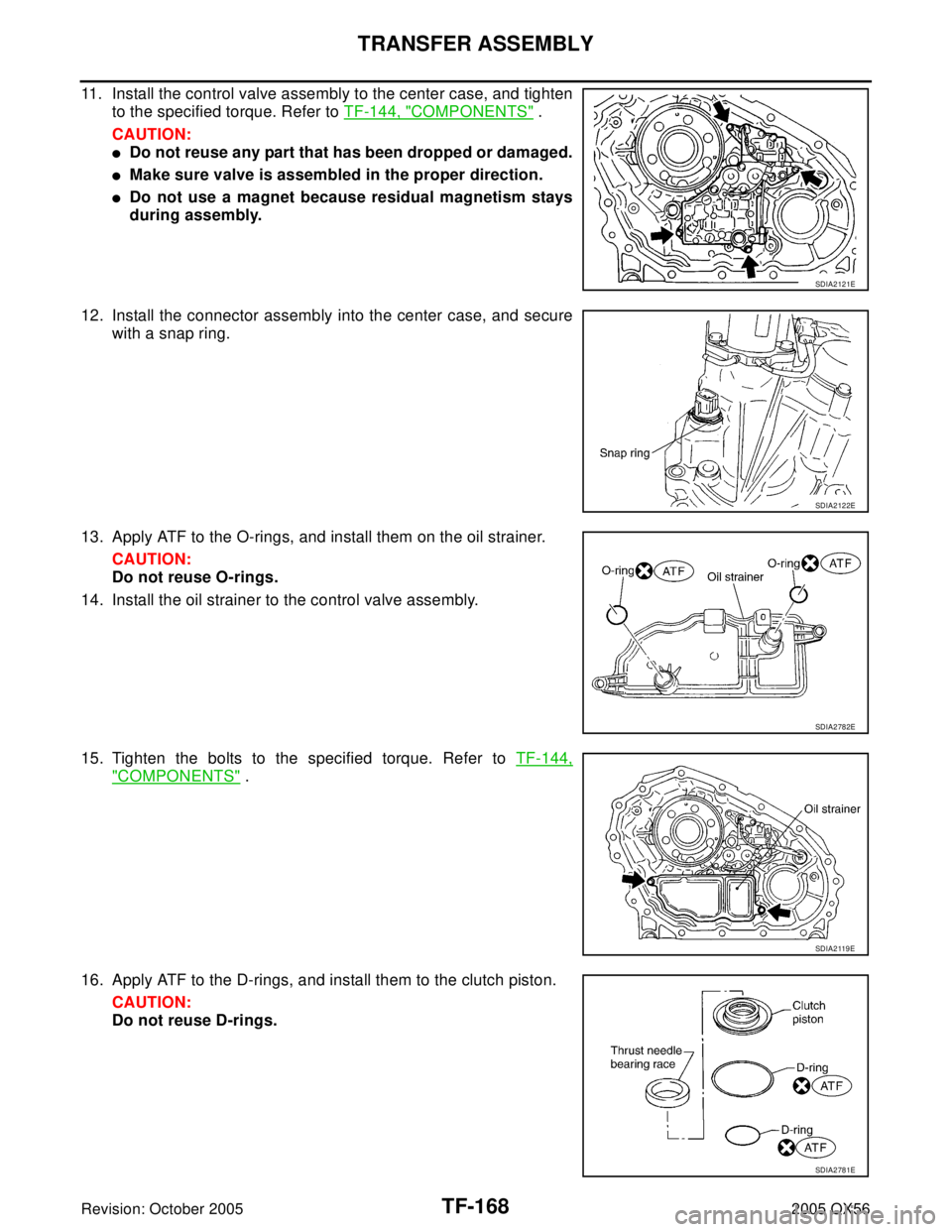
11. Install the control valve assembly to the center case, and tighten
to the specified torque. Refer to TF-144, "
COMPONENTS" .
CAUTION:
�Do not reuse any part that has been dropped or damaged.
�Make sure valve is assembled in the proper direction.
�Do not use a magnet because residual magnetism stays
during assembly.
12. Install the connector assembly into the center case, and secure
with a snap ring.
13. Apply ATF to the O-rings, and install them on the oil strainer.
CAUTION:
Do not reuse O-rings.
14. Install the oil strainer to the control valve assembly.
15. Tighten the bolts to the specified torque. Refer to TF-144,
"COMPONENTS" .
16. Apply ATF to the D-rings, and install them to the clutch piston.
CAUTION:
Do not reuse D-rings.
SDIA2121E
SDIA2122E
SDIA2782E
SDIA2 119 E
SDIA2781E
Page 3312 of 3419

TRANSFER ASSEMBLY
TF-169
C
E
F
G
H
I
J
K
L
MA
B
TF
Revision: October 20052005 QX56
17. Install the thrust needle bearing race to the clutch piston.
18. Install the clutch piston to the center case as shown.
CAUTION:
Install so the fitting protrusion of clutch piston aligns with
the dent of center case.
19. Remove all the sealant from the oil pressure check port and
inside the center case.
CAUTION:
Remove old sealant adhering to mounting surfaces. Also
remove any moisture, oil, or foreign material adhering to
application and mounting surfaces.
20. Thread the oil pressure check plug in 1 or 2 pitches and apply
sealant to the oil pressure check plug threads. Tighten to the
specified torque. Refer to TF-144, "
COMPONENTS" .
�Use Genuine Silicone RTV or equivalent. Refer to GI-45,
"Recommended Chemical Products and Sealants" .
CAUTION:
Do not reuse oil pressure check plug.
21. Install the snap ring to the clutch hub, using suitable tool.
CAUTION:
Do not reuse snap ring.
SDIA2189E
SDIA2190E
SMT915C
WDIA0101E
Page 3316 of 3419

TRANSFER ASSEMBLY
TF-173
C
E
F
G
H
I
J
K
L
MA
B
TF
Revision: October 20052005 QX56
37. Install the inner gear and outer gear in the main oil pump hous-
ing. Then, measure the side clearance. Refer to TF-163, "
Main
Oil Pump" .
38. Install the main oil pump housing, outer gear and inner gear to
the center case.
39. Install the main oil pump cover to the center case, and tighten to
the specified torque. Refer to TF-144, "
COMPONENTS" .
40. Remove all the sealant from the switch mounting area and
inside the center case.
CAUTION:
Remove old sealant adhering to mounting surfaces. Also
remove any moisture, oil, or foreign material adhering to
application and mounting surfaces.
41. Thread the ATP switch and neutral-4LO switch in one to two
pitches and apply sealant to the threads of the switches. Tighten
to the specified torque. Refer to TF-144, "
COMPONENTS" .
�Use Genuine Silicone RTV or equivalent. Refer to GI-45,
"Recommended Chemical Products and Sealants" .
NOTE:
�Neutral-4LO switch harness connector is gray.
�ATP switch harness connector is black.
SDIA2174E
SDIA2188E
SDIA2130E
SDIA2096E
, and install them on the oil filter
(2).
CAUTION:
Do not reuse O-rings.
4. Install the oil filter to the")