Page 1313 of 4731

DI-52
WARNING LAMPS
Revision: 2005 July 2005 FX
5. CHECK OIL PRESSURE SWITCH CIRCUIT
1. Turn ignition switch OFF.
2. Disconnect IPDM E/R connector and oil pressure switch connector.
3. Check continuity between IPDM E/R harness connector E9 ter- minal 57 (BR) and oil pressure switch harness connector F1 ter-
minal 1 (BR).
OK or NG
OK >> GO TO 6.
NG >> Repair harness or connector.
6. CHECK OIL PRESSURE SWITCH
Check oil pressure switch. Refer to DI-53, "
OIL PRESSURE SWITCH" .
OK or NG
OK >> Replace IPDM E/R. Refer to PG-30, "Removal and Installation of IPDM E/R" .
NG >> Replace oil pressure switch.
Oil Pressure Warning Lamp Does Not Turn Off (Oil Pressure Is Normal)AKS005NG
NOTE:
For oil pressure inspection, refer to LU-8, "
OIL PRESSURE CHECK" (VQ35DE) or LU-25, "OIL PRESSURE
CHECK" (VK45DE)
1. CHECK IPDM E/R OUTPUT SIGNAL
1. Turn ignition switch OFF.
2. Disconnect oil pressure switch connector.
3. Turn ignition switch ON.
4. Check voltage between oil pressure switch harness connector F1 terminal 1 (BR) and ground.
OK or NG
OK >> GO TO 2.
NG >> GO TO 3.
2. CHECK OIL PRESSURE SWITCH
1. Turn ignition switch OFF.
2. Check oil pressure switch. Refer to DI-53, "
OIL PRESSURE SWITCH" .
OK or NG
OK >> Replace IPDM E/R. Refer to PG-30, "Removal and Installation of IPDM E/R" .
NG >> Replace oil pressure switch. 57 (BR) – 1 (BR) : Continuity should exist.
PKIB3572E
1 (BR) – Ground : Approx. 12 V
PKIB3573E
Page 1314 of 4731
WARNING LAMPS DI-53
C
D E
F
G H
I
J
L
M A
B
DI
Revision: 2005 July 2005 FX
3. CHECK OIL PRESSURE SWITCH CIRCUIT
1. Disconnect IPDM E/R connector.
2. Check continuity between IPDM E/R harness connector E9 ter- minal 57 (BR) and ground.
OK or NG
OK >> Replace IPDM E/R. Refer to PG-30, "Removal and
Installation of IPDM E/R" .
NG >> Repair harness or connector.
Component InspectionAKS005NH
OIL PRESSURE SWITCH
Check continuity between oil pressure switch and ground. 57 (BR) – Ground : Continuity should not exist.
SKIA5013E
Condition
Oil pressure kPa (kg/cm2 , psi) Continuity
Engine stopped Less than 29 (0.3, 4) Yes Engine running More than 29 (0.3, 4) No
ELF0044D
Page 1347 of 4731
DI-86
LANE DEPARTURE WARNING SYSTEM
Revision: 2005 July 2005 FX
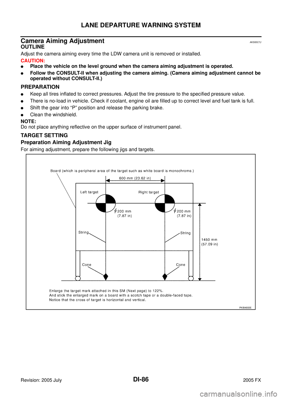
Camera Aiming AdjustmentAKS00C7J
OUTLINE
Adjust the camera aiming every time the LDW camera unit is removed or installed.
CAUTION:
�Place the vehicle on the level ground when the camera aiming adjustment is operated.
�Follow the CONSULT-II when adjusting the camera aiming. (Camera aiming adjustment cannot be
operated without CONSULT-II.)
PREPARATION
�Keep all tires inflated to correct pressures. Adjust the tire pressure to the specified pressure value.
�There is no-load in vehicle. Check if coolant, engine oil are filled up to correct level and fuel tank is full.
�Shift the gear into “P” position and release the parking brake.
�Clean the windshield.
NOTE:
Do not place anything reflective on the upper surface of instrument panel.
TARGET SETTING
Preparation Aiming Adjustment Jig
For aiming adjustment, prepare the following jigs and targets.
PKIB4693E
Page 1478 of 4731
BASIC SERVICE PROCEDURE EC-85
[VQ35DE]
C
D E
F
G H
I
J
K L
M A
EC
Revision: 2005 July 2005 FX
Idle Mixture Ratio AdjustmentABS00E91
PREPARATION
1. Make sure that the following parts are in good order.
�Battery
�Ignition system
�Engine oil and coolant levels
�Fuses
�ECM harness connector
�Va c u u m h o s e s
�Air intake system
(Oil filler cap, oil level gauge, etc.)
�Fuel pressure
�Engine compression
�Throttle valve
�Evaporative emission system
2. On air conditioner equipped models, checks should be carried out while the air conditioner is OFF.
3. On automatic transmission equipped models, when checking idle rpm, ignition timing and mixture ratio, checks should be carried out while selector lever is in P or N position.
4. When measuring CO percentage, insert probe more than 40 cm (15.7 in) into tail pipe.
5. Turn OFF headlamp, heater blower, rear window defogger.
6. Keep front wheels pointed straight ahead.
Page 1503 of 4731
![INFINITI FX35 2005 Service Manual EC-110
[VQ35DE]
TROUBLE DIAGNOSIS
Revision: 2005 July 2005 FX
Symptom Matrix ChartABS006KS
SYSTEM — BASIC ENGINE CONTROL SYSTEM
SYMPTOM
Reference
page
HARD/NO START/RESTART (EXCP. HA)
ENGINE STA](/manual-img/42/57020/w960_57020-1502.png "INFINITI FX35 2005 Service Manual EC-110
[VQ35DE]
TROUBLE DIAGNOSIS
Revision: 2005 July 2005 FX
Symptom Matrix ChartABS006KS
SYSTEM — BASIC ENGINE CONTROL SYSTEM
SYMPTOM
Reference
page
HARD/NO START/RESTART (EXCP. HA)
ENGINE STA")
EC-110
[VQ35DE]
TROUBLE DIAGNOSIS
Revision: 2005 July 2005 FX
Symptom Matrix ChartABS006KS
SYSTEM — BASIC ENGINE CONTROL SYSTEM
SYMPTOM
Reference
page
HARD/NO START/RESTART (EXCP. HA)
ENGINE STALL
HESITATION/SURGING/FLAT SPOT
SPARK KNOCK/DETONATION
LACK OF POWER/POOR ACCELERATION
HIGH IDLE/LOW IDLE
ROUGH IDLE/HUNTING
IDLING VIBRATION
SLOW/NO RETURN TO IDLE
OVERHEATS/WATER TEMPERATURE HIGH
EXCESSIVE FUEL CONSUMPTION
EXCESSIVE OIL CONSUMPTION
BATTERY DEAD (UNDER CHARGE)
Warranty symptom code AA AB AC AD AE AF AG AH AJ AK AL AM HA
Fuel Fuel pump circuit 11232 22 3 2 EC-668
Fuel pressure regulator system334444444 4 EC-99
Injector circuit 11232 22 2 EC-661
Evaporative emission system 334444444 4EC-39
Air Positive crankcase ventilation sys-
tem 33 4444444 41
EC-51
Incorrect idle speed adjustment 1 1 1 1 1 EC-78
Electric throttle control actuator 112332222 2 2 EC-424,
EC-426
IgnitionIncorrect ignition timing adjustment33111 11 1 EC-78
Ignition circuit 11222 22 2EC-648
Power supply and ground circuit22333 33 23 EC-164
Mass air flow sensor circuit
1
12 2
222 2 EC-186,
EC-195
Engine coolant temperature sensor circuit
3 33
EC-208,
EC-220
Air fuel ratio (A/F) sensor EC-488
EC-497
EC-506
EC-516
EC-526
EC-536
EC-548
Throttle position sensor circuit
22 EC-213
,
EC-278
,
EC-479
,
EC-481
,
EC-633
Accelerator pedal position sensor circuit 3 2 1 EC-483
,
EC-619
,
EC-626
,
EC-640
Knock sensor circuit 2 3 EC-295
Crankshaft position sensor (POS) circuit 2 2EC-300
Camshaft position sensor (PHASE) circuit 3 2EC-307
Page 1504 of 4731
![INFINITI FX35 2005 Service Manual TROUBLE DIAGNOSIS EC-111
[VQ35DE]
C
D E
F
G H
I
J
K L
M A
EC
Revision: 2005 July 2005 FX
1 - 6: The numbers refer to the order of inspection.
(continued on next page) Vehicle speed sign](/manual-img/42/57020/w960_57020-1503.png "INFINITI FX35 2005 Service Manual TROUBLE DIAGNOSIS EC-111
[VQ35DE]
C
D E
F
G H
I
J
K L
M A
EC
Revision: 2005 July 2005 FX
1 - 6: The numbers refer to the order of inspection.
(continued on next page) Vehicle speed sign")
TROUBLE DIAGNOSIS EC-111
[VQ35DE]
C
D E
F
G H
I
J
K L
M A
EC
Revision: 2005 July 2005 FX
1 - 6: The numbers refer to the order of inspection.
(continued on next page) Vehicle speed signal circuit 2 3 3 3
EC-391
Power steering pressure sensor circuit 2 3 3EC-397
ECM 22333333333 EC-402,
EC-413
Intake valve timing control solenoid valve cir-
cuit 32 13223 3
EC-417
Park/neutral position (PNP) switch circuit 3 3 3 3 3 EC-609
Refrigerant pressure sensor circuit 2 3 3 4EC-674
Electrical load signal circuit 3EC-679
Air conditioner circuit223333333 3 2 AT C - 4 0
ABS actuator and electric unit (control unit) 4 BRC-12
SYMPTOM
Reference
page
HARD/NO START/RESTART (EXCP. HA)
ENGINE STALL
HESITATION/SURGING/FLAT SPOT
SPARK KNOCK/DETONATION
LACK OF POWER/POOR ACCELERATION
HIGH IDLE/LOW IDLE
ROUGH IDLE/HUNTING
IDLING VIBRATION
SLOW/NO RETURN TO IDLE
OVERHEATS/WATER TEMPERATURE HIGH
EXCESSIVE FUEL CONSUMPTION
EXCESSIVE OIL CONSUMPTION
BATTERY DEAD (UNDER CHARGE)
Warranty symptom code AA AB AC AD AE AF AG AH AJ AK AL AM HA
Page 1550 of 4731
![INFINITI FX35 2005 Service Manual TROUBLE DIAGNOSIS - SPECIFICATION VALUE EC-157
[VQ35DE]
C
D E
F
G H
I
J
K L
M A
EC
Revision: 2005 July 2005 FX
5. CHANGE ENGINE OIL
1. Stop the engine.
2. Change engine oil. NOTE:
This](/manual-img/42/57020/w960_57020-1549.png "INFINITI FX35 2005 Service Manual TROUBLE DIAGNOSIS - SPECIFICATION VALUE EC-157
[VQ35DE]
C
D E
F
G H
I
J
K L
M A
EC
Revision: 2005 July 2005 FX
5. CHANGE ENGINE OIL
1. Stop the engine.
2. Change engine oil. NOTE:
This")
TROUBLE DIAGNOSIS - SPECIFICATION VALUE EC-157
[VQ35DE]
C
D E
F
G H
I
J
K L
M A
EC
Revision: 2005 July 2005 FX
5. CHANGE ENGINE OIL
1. Stop the engine.
2. Change engine oil. NOTE:
This symptom may occur when a large amount of gasoline is mixed with engine oil because of driving
conditions (such as when engine oil temperature does not rise enough since a journey distance is too
short during winter). The symptom will not be detected after changing engine oil or changing driving con-
dition.
>> INSPECTION END
6. CHECK FUEL PRESSURE
Check fuel pressure. (Refer to EC-99, "
Fuel Pressure Check" .)
OK or NG
OK >> GO TO 9.
NG (Fuel pressure is too high)>>Replace fuel pressure regulator, refer to EC-99, "
Fuel Pressure Check" .
GO TO 8.
NG (Fuel pressure is too low)>>GO TO 7.
7. DETECT MALFUNCTIONING PART
1. Check the following.
–Clogged and bent fuel hose and fuel tube
–Clogged fuel filter
–Fuel pump and its circuit (Refer to EC-668, "FUEL PUMP CIRCUIT" .)
2. If NG, repair or replace the malfunctioning part. (Refer to EC-99, "
Fuel Pressure Check" .)
If OK, replace fuel pressure regulator.
>> GO TO 8.
8. CHECK “A/F ALPHA-B1”, “A/F ALPHA-B2”
1. Start engine.
2. Select “A/F ALPHA-B1”, “A/F ALPHA-B2” in “DATA MONITOR (SPEC)” mode, and make sure that the each indication is within the SP value.
OK or NG
OK >> INSPECTION END
NG >> GO TO 9.
9. PERFORM POWER BALANCE TEST
1. Perform “POWER BALANCE” in “ACTIVE TEST” mode.
2. Make sure that the each cylinder produces a momentary engine speed drop.
OK or NG
OK >> GO TO 12.
NG >> GO TO 10.
PBIB0133E
Page 1551 of 4731
![INFINITI FX35 2005 Service Manual EC-158
[VQ35DE]
TROUBLE DIAGNOSIS - SPECIFICATION VALUE
Revision: 2005 July 2005 FX
10. DETECT MALFUNCTIONING PART
1. Check the following.
–Ignition coil and its circuit (Refer to EC-648, "IGNITI](/manual-img/42/57020/w960_57020-1550.png "INFINITI FX35 2005 Service Manual EC-158
[VQ35DE]
TROUBLE DIAGNOSIS - SPECIFICATION VALUE
Revision: 2005 July 2005 FX
10. DETECT MALFUNCTIONING PART
1. Check the following.
–Ignition coil and its circuit (Refer to EC-648, \"IGNITI")
EC-158
[VQ35DE]
TROUBLE DIAGNOSIS - SPECIFICATION VALUE
Revision: 2005 July 2005 FX
10. DETECT MALFUNCTIONING PART
1. Check the following.
–Ignition coil and its circuit (Refer to EC-648, "IGNITION SIGNAL" .)
–Fuel injector and its circuit (Refer to EC-661, "INJECTOR CIRCUIT" .)
–Intake air leakage
–Low compression pressure (Refer to EM-100, "CHECKING COMPRESSION PRESSURE" .)
2. If NG, repair or replace the malfunctioning part. If OK, replace fuel injector. (It may be caused by leakage from fuel injector or clogging.)
>> GO TO 11.
11 . CHECK “A/F ALPHA-B1”, “A/F ALPHA-B2”
1. Start engine.
2. Select “A/F ALPHA-B1”, “A/F ALPHA-B2” in “DATA MONITOR (SPEC)” mode, and make sure that the each indication is within the SP value.
OK or NG
OK >> INSPECTION END
NG >> GO TO 12.
12. CHECK A/F SENSOR 1 FUNCTION
Perform all DTC Confirmation Procedure related with A/F sensor 1.
�For DTC P1271, P1281, refer to EC-488, "DTC Confirmation Procedure" .
�For DTC P1272, P1282, refer to EC-497, "DTC Confirmation Procedure" .
�For DTC P1273, P1283, refer to EC-506, "DTC Confirmation Procedure" .
�For DTC P1274, P1284, refer to EC-516, "DTC Confirmation Procedure" .
�For DTC P1276, P1286, refer to EC-526, "DTC Confirmation Procedure" .
�For DTC P1278, P1288, refer to EC-537, "DTC Confirmation Procedure" .
�For DTC P1279, P1289, refer to EC-549, "DTC Confirmation Procedure" .
OK or NG
OK >> GO TO 15.
NG >> GO TO 13.
13. CHECK A/F SENSOR 1 CIRCUIT
Perform Diagnostic Procedure according to corresponding DTC.
>> GO TO 14.
14. CHECK “A/F ALPHA-B1”, “A/F ALPHA-B2”
1. Start engine.
2. Select “A/F ALPHA-B1”, “A/F ALPHA-B2” in “DATA MONITOR (SPEC)” mode, and make sure that the each indication is within the SP value.
OK or NG
OK >> INSPECTION END
NG >> GO TO 15.

![INFINITI FX35 2005 Service Manual BASIC SERVICE PROCEDURE EC-85
[VQ35DE]
C
D E
F
G H
I
J
K L
M A
EC
Revision: 2005 July 2005 FX
Idle Mixture Ratio AdjustmentABS00E91
PREPARATION
1. Make sure that the following parts are i](/manual-img/42/57020/w960_57020-1477.png "INFINITI FX35 2005 Service Manual BASIC SERVICE PROCEDURE EC-85
[VQ35DE]
C
D E
F
G H
I
J
K L
M A
EC
Revision: 2005 July 2005 FX
Idle Mixture Ratio AdjustmentABS00E91
PREPARATION
1. Make sure that the following parts are i")