Page 430 of 4731
ASSEMBLY AT-347
D E
F
G H
I
J
K L
M A
B
AT
Revision: 2005 July 2005 FX
g. Install control valve with TCM in transmission case.
CAUTION:
�Make sure that turbine revolution sensor securely installs
turbine revolution sensor hole.
�Hang down revolution sensor harness toward outside so
as not to disturb installation of control valve with TCM.
�Adjust A/T assembly harness connector of control valve
with TCM to terminal hole of transmission case.
�Assemble it so that manual valve cutout is engaged with
manual plate projection.
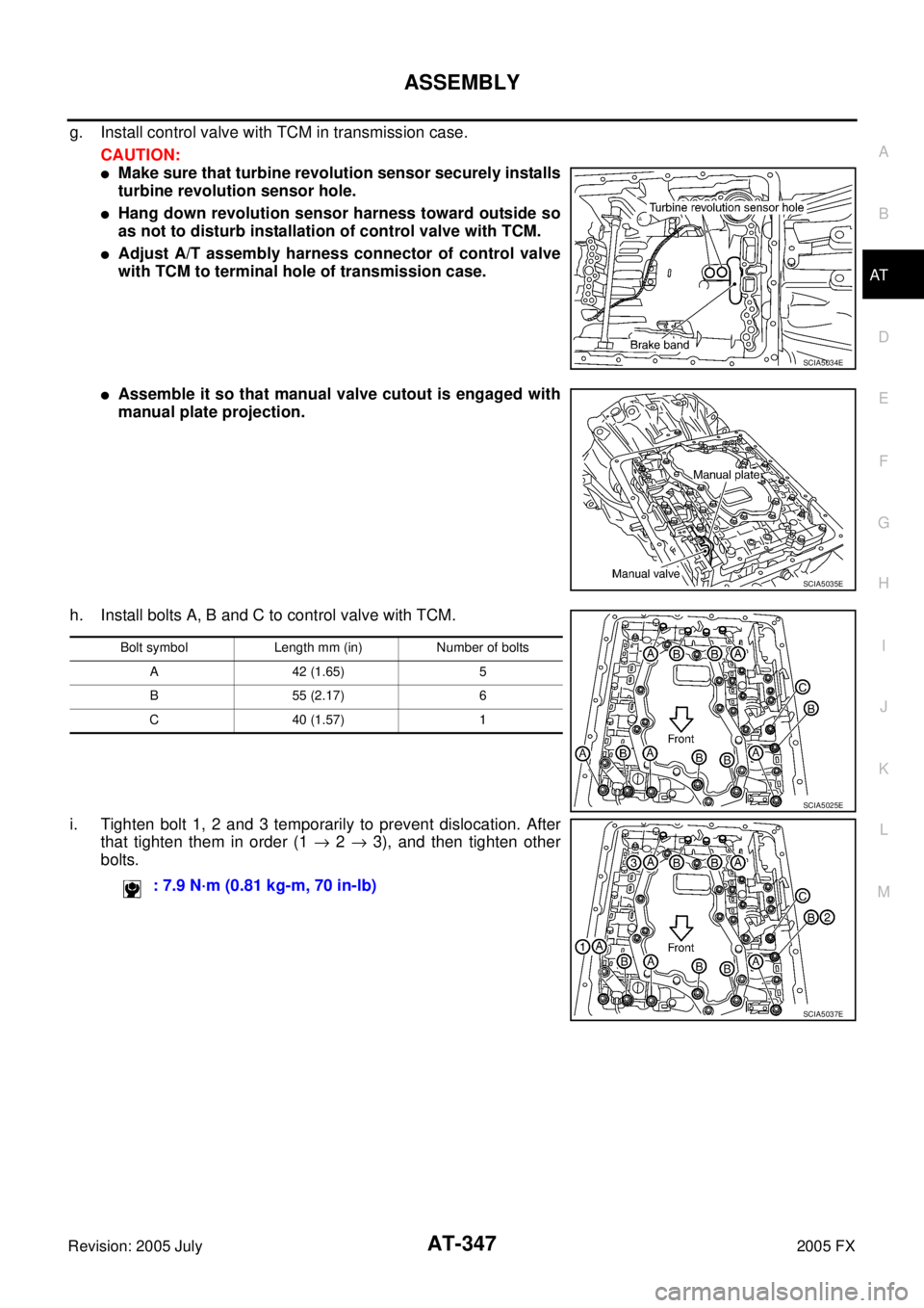
h. Install bolts A, B and C to control valve with TCM.
i. Tighten bolt 1, 2 and 3 temporarily to prevent dislocation. After that tighten them in order (1 → 2 → 3), and then tighten other
bolts.
SCIA5034E
SCIA5035E
Bolt symbol Length mm (in) Number of bolts
A 42 (1.65) 5
B 55 (2.17) 6
C 40 (1.57) 1
: 7.9 N·m (0.81 kg-m, 70 in-lb)
SCIA5025E
SCIA5037E
Page 431 of 4731
AT-348
ASSEMBLY
Revision: 2005 July 2005 FX
10. Connect A/T fluid temperature sensor 2 connector.
11. Securely fasten terminal cord assembly and A/T fluid tempera-
ture sensor 2 harness with terminal clips.
12. Connect revolution sensor connector.
13. Securely fasten revolution sensor 2 harness with terminal clips.
14. Pull down A/T assembly harness connector. CAUTION:
Be careful not to damage connector.
SCIA5023E
SCIA5446E
SCIA5024E
SCIA5293E
SCIA5299E
Page 446 of 4731

PRECAUTIONS ATC-9
C
D E
F
G H
I
K L
M A
B
AT C
Revision: 2005 July 2005 FX
REMOVAL
1. Clean piping connection point, and set a disconnector.
2. Slide disconnector in axial direction of piping, and stretch garter spring with tapered point of disconnector.
3. Slide disconnector farther so that inside diameter of garter spring becomes larger than outside diameter of female-side piping flare. Then male-side piping can be disconnected.
INSTALLATION
1. Clean piping connection points, and insert male-side piping into female-side piping.
2. Push inserted male-side piping harder so that female-side piping flare stretches garter spring.
3. If inside diameter of garter spring becomes larger than outside diameter of female-side piping flare, garter spring seats on flare. Then, it fits in between male-side piping cage and female-side piping flare to anchor
piping connection point.
NOTICE:
When garter spring seats on flare, and fits in between male-side piping cage and female-side piping flare,
it clicks.
CAUTION:
�Female-side piping connection point is thin. So, when inserting male-side piping, take care not
to deform female-side piping. Slowly insert it in axial direction.
�Insert piping securely until a click is heard.
SJIA0106E
SJIA0107E
Page 461 of 4731

ATC-24
REFRIGERATION SYSTEM
Revision: 2005 July 2005 FX
Operation
1. Control Valve
–By changing high-pressure valve lift amount, built-in compressor control valve executes the following:
Controls high-pressure valve discharge amount.
Changes crankcase pressure in compressor.
Changes angle of wobble (swash) plate.
–Amount of high-pressure valve lift is determined by factors below.
Low-pressure applied to diaphragm
Spring load of set spring
Balance of magnetic force generated by magnet coil
–Electronic control valve (ECV) magnet coil receives electric signal (duty control) from unified meter and A/
C amp. (Auto amp.) Then, magnetic force generated by electric current is changed to control high-pres-
sure valve lift amount.
2. Maximum Cooling High-pressure valve is closed by magnetic force generated by electric signal sent from unified meter and
A/C amp. At this time, cylinder moves full stroke due to pressure balance between inside crankcase (Pc)
and suction line (Ps).
Under this condition, the wobble (swash) plate is set to the maximum stroke position.
3. Capacity Control When no electric signal is sent from unified meter and A/C amp. (current: OFF), high-pressure valve is
opened by spring force.
Since suction pressure is low, it makes the suction port close and the discharge port open. Thus, crank-
case pressure becomes high as high-pressure enters the crankcase.
–The force acts around the journal pin near the wobble (swash) plate, and is generated by the pressure dif-
ference before and behind the piston.
–The drive lug and journal pin are located where the piston generates the highest pressure. Piston pres-
sure is between suction pressure Ps and discharge pressure Pd, which is close to suction pressure Ps. If
crankcase pressure Pc rises due to capacity control, the force around the journal pin makes the wobble
(swash) plate angle decrease and also the piston stroke decrease. In other words, crankcase pressure
SJIA0547E
Page 468 of 4731

AIR CONDITIONER CONTROL ATC-31
C
D E
F
G H
I
K L
M A
B
AT C
Revision: 2005 July 2005 FX
TRANSMISSION DATA AND TRANSMISSION ORDER
Unified meter and A/C amp. data is transmitted consecutively to each of the door motors following the form
shown in figure below.
Start:
Initial compulsory signal sent to each of the door motors.
Address:
Data sent from the unified meter and A/C amp. are selected according to data-based decisions made by the
air mix door motor, mode door motor and intake door motor.
If the addresses are identical, the opening angle data and error check signals are received by the door motor
LCUs. The LCUs then make the appropriate error decision. If the opening angle data have no error, door con-
trol begins.
If an error exists, the received data are rejected and corrected data received. Finally, door control is based
upon the corrected opening angle data.
Opening Angle:
Data that shows the indicated door opening angle of each door motor.
Error Check:
Procedure by which sent and received data is checked for errors. Error data are then compiled. The error
check prevents corrupted data from being used by the air mix door motor, the mode door motor and the intake
door motor. Error data can be related to the following symptoms.
�Malfunction of electrical frequency
�Poor electrical connections
�Signal leakage from transmission lines
�Signal level fluctuation
RJIA1748E
Page 557 of 4731

ATC-120
INTAKE SENSOR
Revision: 2005 July 2005 FX
INTAKE SENSORPFP:27723
Removal and InstallationAJS0015D
REMOVAL
1. Remove low-pressure pipe 2 and high-pressure pipe 3. Refer to ATC-152, "Removal and Installation of
Low-Pressure Pipe 2 and High-Pressure Pipe 3" .
CAUTION:
Cap or wrap the joint of the pipe with suitable material such as vinyl tape to avoid the entry of air.
2. Slide evaporator to passenger side, and then remove intake sensor.
INSTALLATION
Installation is basically the reverse order of removal.
CAUTION:
�Replace O-rings of A/C piping with new ones, and then apply compressor oil to it when installing
it.
�Mark the mounting position of intake sensor bracket prior to removal so that the reinstalled sen-
sor can be located in the same position.
�Connection point for female-side piping is thin. So, when inserting male-side piping, take care not
to deform female-side piping. Slowly insert in axial direction.
�Insert one-touch joint connection point securely until it clicks.
�After piping has been connected, pull male-side piping by hand to make sure piping does not
come off.
�When recharging refrigerant, check for leaks.
RJIA0928E
Page 558 of 4731
BLOWER UNIT ATC-121
C
D E
F
G H
I
K L
M A
B
AT C
Revision: 2005 July 2005 FX
BLOWER UNITPFP:27200
Removal and InstallationAJS0015E
REMOVAL
1. Remove instrument passenger lower panel. Refer to IP-11, "Removal and Installation" .
2. Remove mounting nuts, and then remove ECM with bracket attached.
3. Disconnect intake door motor connector and blower fan motor connector.
4. Remove harness clip from blower unit.
5. Remove mounting bolt and screws from blower unit.
CAUTION:
Move blower unit rightward, and remove locating pin (1
part) and joint. Then remove blower unit downward.
6. Remove blower unit.
INSTALLATION
Installation is basically the reverse order of removal.
CAUTION:
Make sure locating pin (1 part) and joint are securely inserted.
RJIA2039E
RJIA0943E
Page 564 of 4731
.")
HEATER & COOLING UNIT ASSEMBLY ATC-127
C
D E
F
G H
I
K L
M A
B
AT C
Revision: 2005 July 2005 FX
11. Remove mounting nuts and bolts, and then remove instrument stays (left and right side).
12. Remove mounting bolts from heater & cooling unit assembly.
13. Disconnect drain hose.
14. Remove ventilator ducts, defroster nozzle and ducts.
15. Remove steering member mounting bolts, nut and harness clips.
16. Remove the steering member, and then remove heater & cooling unit assembly.
INSTALLATION
Installation is basically the reverse order of removal.
CAUTION:
�Replace O-rings of A/C piping with new ones, and then apply compressor oil to it when installing
it.
�Connection point for female-side piping is thin. So, when inserting male-side piping, take care not
to deform female-side piping. Slowly insert in axial direction.
�Insert one-touch joint connection point securely until it clicks.
�After piping has been connected, pull male-side piping by hand to make sure piping does not
come off.
RJIA2042E
RJIA2044E
RJIA2043E