Page 259 of 4731
AT-176
DTC P1841 ATF PRESSURE SWITCH 1
Revision: 2005 July 2005 FX
Diagnostic ProcedureACS002QM
1. CHECK INPUT SIGNAL
With CONSULT-II
1. Start engine.
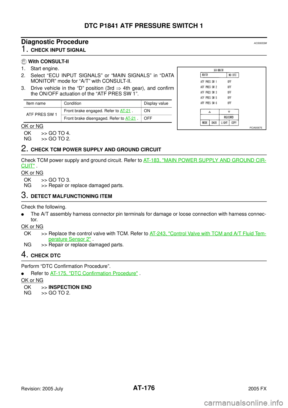
2. Select “ECU INPUT SIGNALS” or “MAIN SIGNALS” in “DATA MONITOR” mode for “A/T” with CONSULT-II.
3. Drive vehicle in the “D” position (3rd � 4th gear), and confirm
the ON/OFF actuation of the “ATF PRES SW 1”.
OK or NG
OK >> GO TO 4.
NG >> GO TO 2.
2. CHECK TCM POWER SUPPLY AND GROUND CIRCUIT
Check TCM power supply and ground circuit. Refer to AT- 1 8 3 , "
MAIN POWER SUPPLY AND GROUND CIR-
CUIT" .
OK or NG
OK >> GO TO 3.
NG >> Repair or replace damaged parts.
3. DETECT MALFUNCTIONING ITEM
Check the following.
�The A/T assembly harness connector pin terminals for damage or loose connection with harness connec-
tor.
OK or NG
OK >> Replace the control valve with TCM. Refer to AT- 2 4 3 , "Control Valve with TCM and A/T Fluid Tem-
perature Sensor 2" .
NG >> Repair or replace damaged parts.
4. CHECK DTC
Perform “DTC Confirmation Procedure”.
�Refer to AT- 1 7 5 , "DTC Confirmation Procedure" .
OK or NG
OK >> INSPECTION END
NG >> GO TO 2.
Item name Condition Display value
ATF PRES SW 1 Front brake engaged. Refer to
AT- 2 1
.ON
Front brake disengaged. Refer to AT- 2 1
.OFF
PCIA0067E
Page 261 of 4731
AT-178
DTC P1843 ATF PRESSURE SWITCH 3
Revision: 2005 July 2005 FX
Diagnostic ProcedureACS002QR
1. CHECK INPUT SIGNAL
With CONSULT-II
1. Start engine.
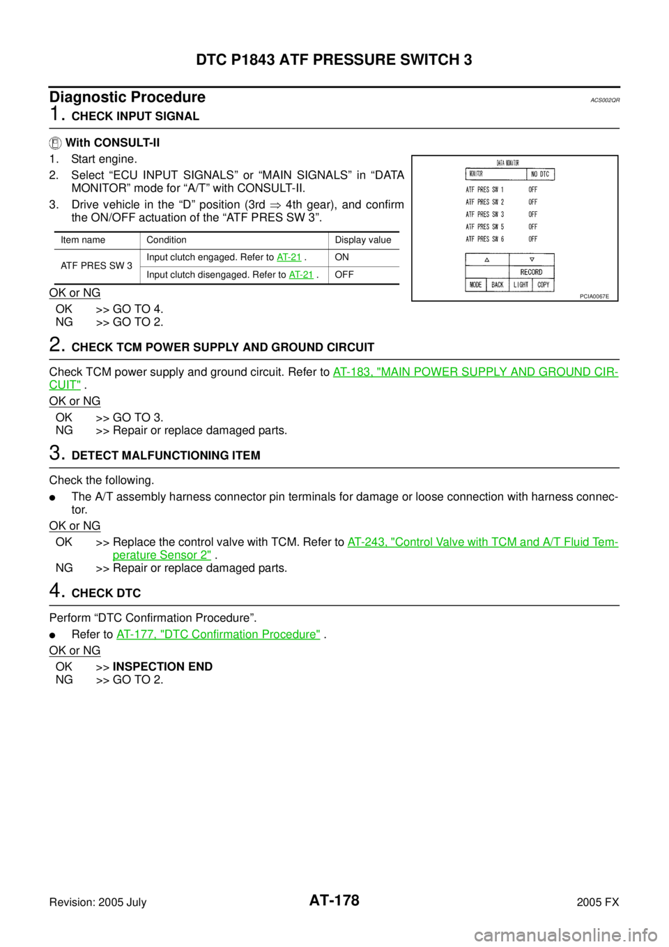
2. Select “ECU INPUT SIGNALS” or “MAIN SIGNALS” in “DATA MONITOR” mode for “A/T” with CONSULT-II.
3. Drive vehicle in the “D” position (3rd � 4th gear), and confirm
the ON/OFF actuation of the “ATF PRES SW 3”.
OK or NG
OK >> GO TO 4.
NG >> GO TO 2.
2. CHECK TCM POWER SUPPLY AND GROUND CIRCUIT
Check TCM power supply and ground circuit. Refer to AT- 1 8 3 , "
MAIN POWER SUPPLY AND GROUND CIR-
CUIT" .
OK or NG
OK >> GO TO 3.
NG >> Repair or replace damaged parts.
3. DETECT MALFUNCTIONING ITEM
Check the following.
�The A/T assembly harness connector pin terminals for damage or loose connection with harness connec-
tor.
OK or NG
OK >> Replace the control valve with TCM. Refer to AT- 2 4 3 , "Control Valve with TCM and A/T Fluid Tem-
perature Sensor 2" .
NG >> Repair or replace damaged parts.
4. CHECK DTC
Perform “DTC Confirmation Procedure”.
�Refer to AT- 1 7 7 , "DTC Confirmation Procedure" .
OK or NG
OK >> INSPECTION END
NG >> GO TO 2.
Item name Condition Display value
ATF PRES SW 3 Input clutch engaged. Refer to
AT- 2 1
.ON
Input clutch disengaged. Refer to AT- 2 1
.OFF
PCIA0067E
Page 263 of 4731
AT-180
DTC P1845 ATF PRESSURE SWITCH 5
Revision: 2005 July 2005 FX
Diagnostic ProcedureACS002QW
1. CHECK INPUT SIGNAL
With CONSULT-II
1. Start engine.
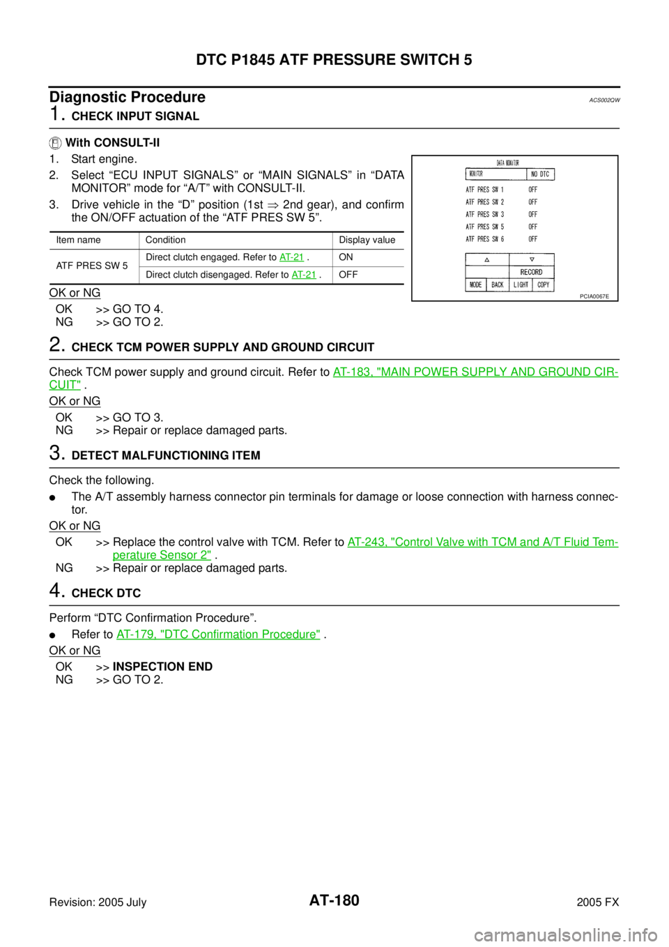
2. Select “ECU INPUT SIGNALS” or “MAIN SIGNALS” in “DATA MONITOR” mode for “A/T” with CONSULT-II.
3. Drive vehicle in the “D” position (1st � 2nd gear), and confirm
the ON/OFF actuation of the “ATF PRES SW 5”.
OK or NG
OK >> GO TO 4.
NG >> GO TO 2.
2. CHECK TCM POWER SUPPLY AND GROUND CIRCUIT
Check TCM power supply and ground circuit. Refer to AT- 1 8 3 , "
MAIN POWER SUPPLY AND GROUND CIR-
CUIT" .
OK or NG
OK >> GO TO 3.
NG >> Repair or replace damaged parts.
3. DETECT MALFUNCTIONING ITEM
Check the following.
�The A/T assembly harness connector pin terminals for damage or loose connection with harness connec-
tor.
OK or NG
OK >> Replace the control valve with TCM. Refer to AT- 2 4 3 , "Control Valve with TCM and A/T Fluid Tem-
perature Sensor 2" .
NG >> Repair or replace damaged parts.
4. CHECK DTC
Perform “DTC Confirmation Procedure”.
�Refer to AT- 1 7 9 , "DTC Confirmation Procedure" .
OK or NG
OK >> INSPECTION END
NG >> GO TO 2.
Item name Condition Display value
ATF PRES SW 5 Direct clutch engaged. Refer to
AT- 2 1
.ON
Direct clutch disengaged. Refer to AT- 2 1
.OFF
PCIA0067E
Page 265 of 4731
AT-182
DTC P1846 ATF PRESSURE SWITCH 6
Revision: 2005 July 2005 FX
Diagnostic ProcedureACS002R1
1. CHECK INPUT SIGNAL
With CONSULT-II
1. Start the engine.
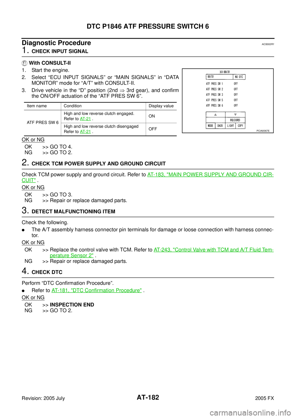
2. Select “ECU INPUT SIGNALS” or “MAIN SIGNALS” in “DATA MONITOR” mode for “A/T” with CONSULT-II.
3. Drive vehicle in the “D” position (2nd � 3rd gear), and confirm
the ON/OFF actuation of the “ATF PRES SW 6”.
OK or NG
OK >> GO TO 4.
NG >> GO TO 2.
2. CHECK TCM POWER SUPPLY AND GROUND CIRCUIT
Check TCM power supply and ground circuit. Refer to AT- 1 8 3 , "
MAIN POWER SUPPLY AND GROUND CIR-
CUIT" .
OK or NG
OK >> GO TO 3.
NG >> Repair or replace damaged parts.
3. DETECT MALFUNCTIONING ITEM
Check the following.
�The A/T assembly harness connector pin terminals for damage or loose connection with harness connec-
tor.
OK or NG
OK >> Replace the control valve with TCM. Refer to AT- 2 4 3 , "Control Valve with TCM and A/T Fluid Tem-
perature Sensor 2" .
NG >> Repair or replace damaged parts.
4. CHECK DTC
Perform “DTC Confirmation Procedure”.
�Refer to AT- 1 8 1 , "DTC Confirmation Procedure" .
OK or NG
OK >> INSPECTION END
NG >> GO TO 2.
Item name Condition Display value
ATF PRES SW 6 High and low reverse clutch engaged.
Refer to AT- 2 1
. ON
High and low reverse clutch disengaged
Refer to AT- 2 1
. OFFPCIA0067E
Page 270 of 4731
CLOSED THROTTLE POSITION AND WIDE OPEN THROTTLE POSITION CIR- CUIT
AT-187
D E
F
G H
I
J
K L
M A
B
AT
Revision: 2005 July 2005 FX
CLOSED THROTTLE POSITION AND WIDE OPEN THROTTLE POSITION CIR-
CUIT
PFP:18002
CONSULT-II Reference ValueACS006CR
Diagnostic ProcedureACS002R2
1. CHECK CAN COMMUNICATION LINE
Perform the self-diagnosis. Refer to AT- 9 3 , "
SELF-DIAGNOSTIC RESULT MODE" , AT- 1 0 3 , "Diagnostic Pro-
cedure without CONSULT-II" .
Is a malfunction in the CAN communication indicated in the results?
YES >> Check CAN communication line. Refer to AT- 1 0 6 , "DTC U1000 CAN COMMUNICATION LINE" .
NO >> GO TO 2.
2. CHECK THROTTLE POSITION SIGNAL CIRCUIT
With CONSULT-II
1. Turn ignition switch ON. (Do not start engine.)
2. Select “ECU INPUT SIGNALS” in “DATA MONITOR” mode for “A/T” with CONSULT-II.
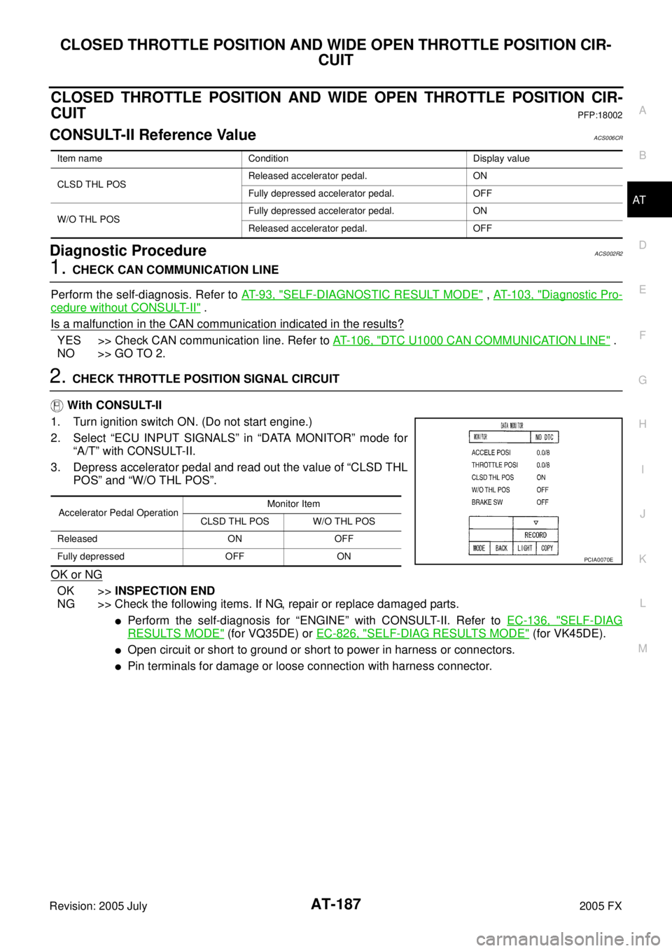
3. Depress accelerator pedal and read out the value of “CLSD THL POS” and “W/O THL POS”.
OK or NG
OK >> INSPECTION END
NG >> Check the following items. If NG, repair or replace damaged parts.
�Perform the self-diagnosis for “ENGINE” with CONSULT-II. Refer to EC-136, "SELF-DIAG
RESULTS MODE" (for VQ35DE) or EC-826, "SELF-DIAG RESULTS MODE" (for VK45DE).
�Open circuit or short to ground or short to power in harness or connectors.
�Pin terminals for damage or loose connection with harness connector.
Item name Condition Display value
CLSD THL POS Released accelerator pedal. ON
Fully depressed accelerator pedal. OFF
W/O THL POS Fully depressed accelerator pedal. ON
Released accelerator pedal. OFF
Accelerator Pedal Operation Monitor Item
CLSD THL POS W/O THL POS
Released ON OFF
Fully depressed OFF ON
PCIA0070E
Page 271 of 4731
AT-188
BRAKE SIGNAL CIRCUIT
Revision: 2005 July 2005 FX
BRAKE SIGNAL CIRCUITPFP:25320
CONSULT-II Reference ValueACS006CS
Diagnostic ProcedureACS002R3
1. CHECK CAN COMMUNICATION LINE
Perform the self-diagnosis. Refer to AT- 9 3 , "
SELF-DIAGNOSTIC RESULT MODE" , AT- 1 0 3 , "Diagnostic Pro-
cedure without CONSULT-II" .
Is a malfunction in the CAN communication indicated in the results?
YES >> Check CAN communication line. Refer to AT- 1 0 6 , "DTC U1000 CAN COMMUNICATION LINE" .
NO >> GO TO 2.
2. CHECK STOP LAMP SWITCH CIRCUIT
With CONSULT-II
1. Turn ignition switch ON. (Do not start engine.)
2. Select “ECU INPUT SIGNALS” in “DATA MONITOR” mode for “A/T” with CONSULT-II.
3. Read out ON/OFF switching action of the “BRAKE SW”.
OK or NG
OK >> INSPECTION END
NG >> GO TO 3.
3. CHECK STOP LAMP SWITCH
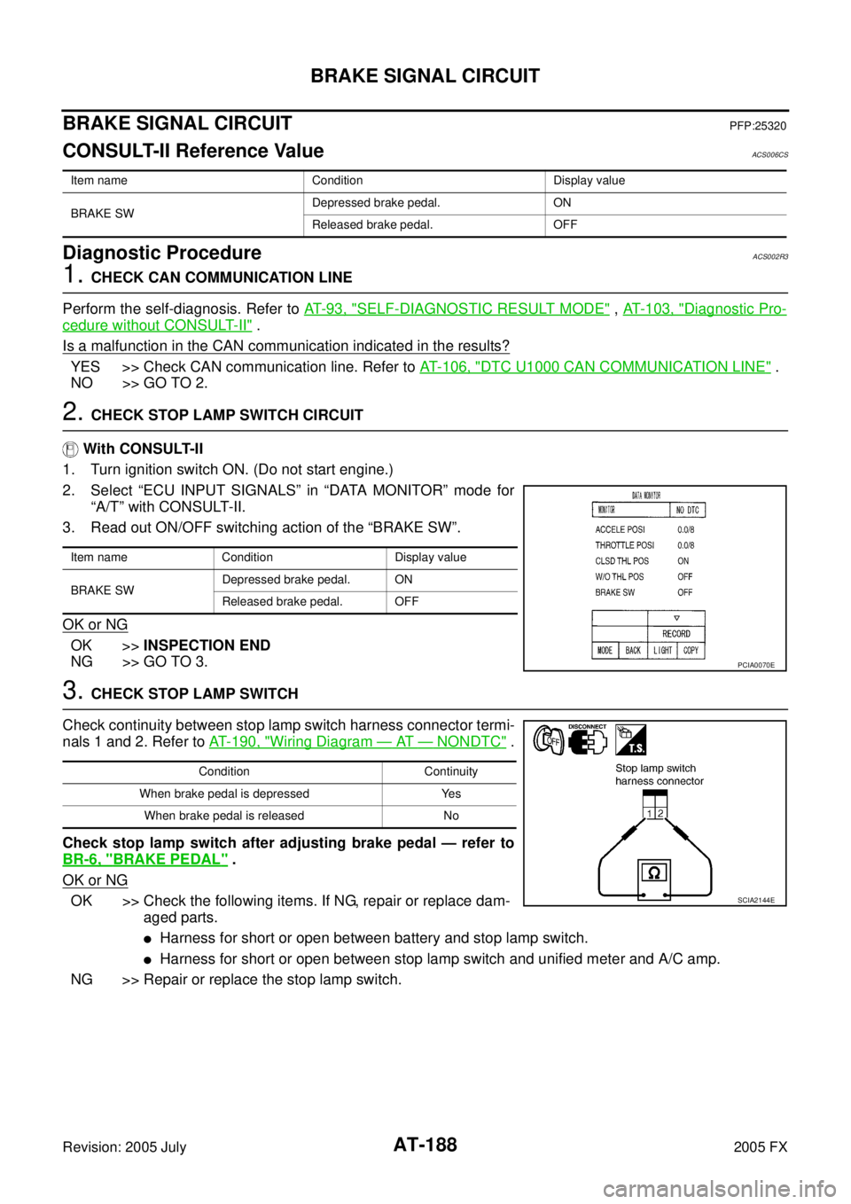
Check continuity between stop lamp switch harness connector termi-
nals 1 and 2. Refer to AT- 1 9 0 , "
Wiring Diagram — AT — NONDTC" .
Check stop lamp switch after adjusting brake pedal — refer to
BR-6, "
BRAKE PEDAL" .
OK or NG
OK >> Check the following items. If NG, repair or replace dam- aged parts.
�Harness for short or open between battery and stop lamp switch.
�Harness for short or open between stop lamp switch and unified meter and A/C amp.
NG >> Repair or replace the stop lamp switch.
Item name Condition Display value
BRAKE SW Depressed brake pedal. ON
Released brake pedal. OFF
Item name Condition Display value
BRAKE SW Depressed brake pedal. ON
Released brake pedal. OFF
PCIA0070E
Condition Continuity
When brake pedal is depressed Yes When brake pedal is released No
SCIA2144E
Page 323 of 4731
AT-240
KEY INTERLOCK CABLE
Revision: 2005 July 2005 FX
KEY INTERLOCK CABLEPFP:34908
ComponentsACS002RX
CAUTION:
�Install key interlock cable in such a way that it will not be damaged by sharp bends, twists or inter-
ference with adjacent parts.
�After installing key interlock cable to control device, make sure that casing cap and bracket are
firmly secured in their positions. If casing cap be removed with an external load of less than 39.2 N
(4.0 kg, 8.8 lb), replace key interlock cable with new one.
SCIA2150E
Page 331 of 4731
AT-248
ON-VEHICLE SERVICE
Revision: 2005 July 2005 FX
3. Connect TCM connectors.
4. Install O-ring in A/T assembly harness connector.
CAUTION:
�Do not reuse O-ring.
�Apply ATF to O-ring.
5. Install A/T fluid temperature sensor 2 to bracket.
6. Install A/T fluid temperature sensor 2 (with bracket) in control valve with TCM.
CAUTION:
Adjust bolt hole of bracket to bolt hole of control valve with
TCM.
7. Install control valve with TCM in transmission case. CAUTION:
�Make sure that turbine revolution sensor securely installs
turbine revolution sensor hole.
�Hang down revolution sensor harness toward outside so
as not to disturb installation of control valve with TCM.
�Adjust A/T assembly harness connector of control valve
with TCM to terminal hole of transmission case.
SCIA5447E
SCIA5155E
SCIA5264E
: 7.9 N·m (0.81 kg-m, 70 in-lb)
SCIA5301E
SCIA5034E