Page 525 of 4731

ATC-88
TROUBLE DIAGNOSIS
Revision: 2005 July 2005 FX
8. CHECK REFRIGERANT PRESSURE SENSOR
WITH CONSULT-II
1. Start the engine.
2. Check voltage of refrigerant pressure sensor. Refer to EC-147, "
CONSULT-II Reference Value in Data
Monitor" (VQ35DE) or EC-838, "CONSULT-II Reference Value in Data Monitor" (VK45DE).
WITHOUT CONSULT-II
1. Start the engine.
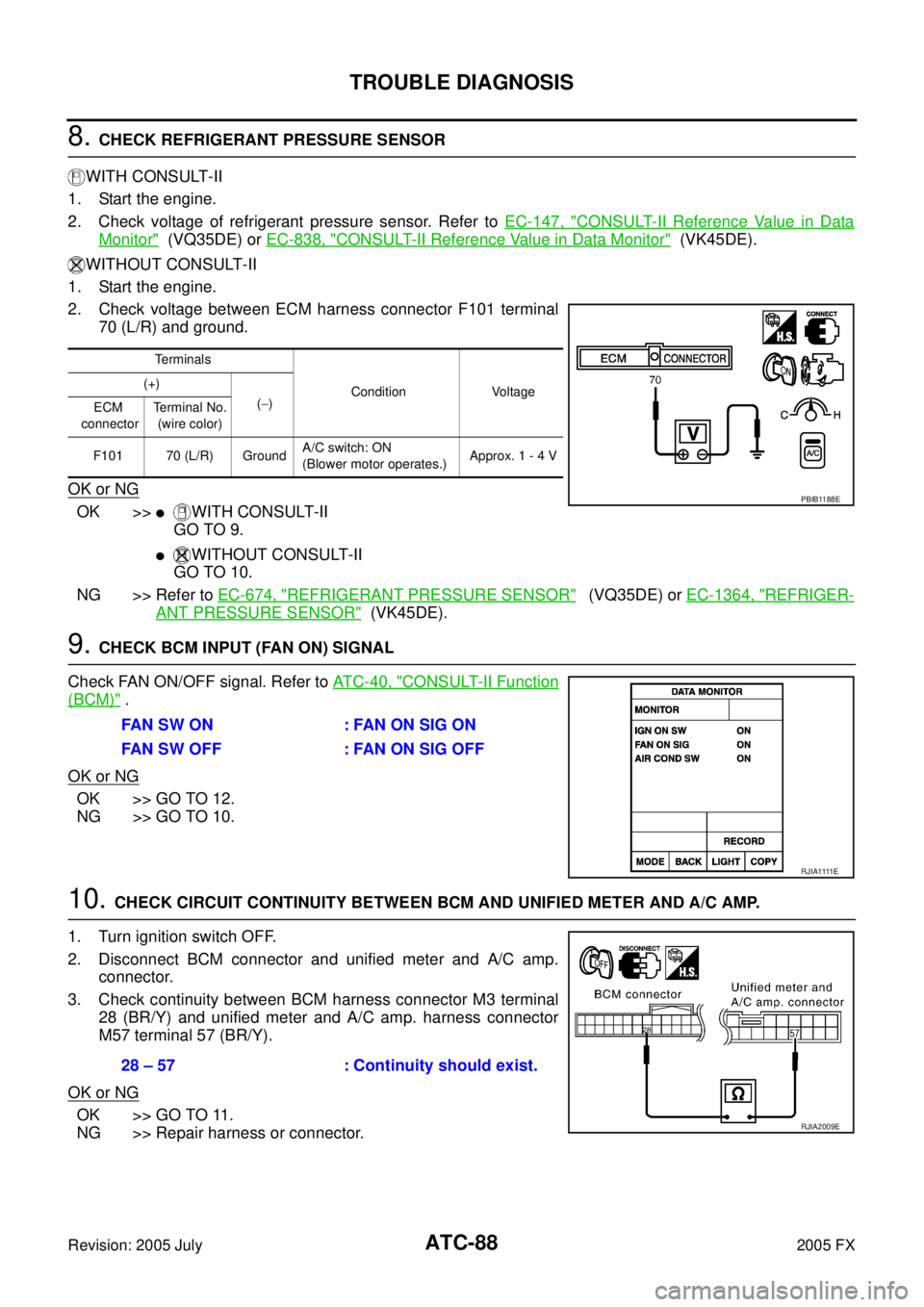
2. Check voltage between ECM harness connector F101 terminal 70 (L/R) and ground.
OK or NG
OK >>�WITH CONSULT-II
GO TO 9.
�WITHOUT CONSULT-II
GO TO 10.
NG >> Refer to EC-674, "
REFRIGERANT PRESSURE SENSOR" (VQ35DE) or EC-1364, "REFRIGER-
ANT PRESSURE SENSOR" (VK45DE).
9. CHECK BCM INPUT (FAN ON) SIGNAL
Check FAN ON/OFF signal. Refer to AT C - 4 0 , "
CONSULT-II Function
(BCM)" .
OK or NG
OK >> GO TO 12.
NG >> GO TO 10.
10. CHECK CIRCUIT CONTINUITY BETWEEN BCM AND UNIFIED METER AND A/C AMP.
1. Turn ignition switch OFF.
2. Disconnect BCM connector and unified meter and A/C amp. connector.
3. Check continuity between BCM harness connector M3 terminal 28 (BR/Y) and unified meter and A/C amp. harness connector
M57 terminal 57 (BR/Y).
OK or NG
OK >> GO TO 11.
NG >> Repair harness or connector.
Te r m i n a l s
Condition Voltage
(+)
( − )
ECM
connector Terminal No.
(wire color)
F101 70 (L/R) Ground A/C switch: ON
(Blower motor operates.) Approx. 1 - 4 V
PBIB1188E
FAN SW ON : FAN ON SIG ON
FAN SW OFF : FAN ON SIG OFF
R J I A 1111 E
28 – 57 : Continuity should exist.
RJIA2009E
Page 527 of 4731
ATC-90
TROUBLE DIAGNOSIS
Revision: 2005 July 2005 FX
COMPONENT INSPECTION
Refrigerant Pressure Sensor
The refrigerant pressure sensor is attached to the condenser.
Make sure that the A/C refrigerant pressure and the sensor output
voltage are within the specified range as shown in the A/C operating
condition figure. Refer to EC-674, "
REFRIGERANT PRESSURE
SENSOR" (VQ35DE) or EC-1364, "REFRIGERANT PRESSURE
SENSOR" (VK45DE).
RJIA2011E
RJIA2954E
Page 529 of 4731
ATC-92
TROUBLE DIAGNOSIS
Revision: 2005 July 2005 FX
*1ATC-54, "FUNCTION CONFIRMA-
TION PROCEDURE", see No. 4 to 6. *2
ATC-73, "
Air Mix Door Motor Circuit"*3ATC-95, "Test Reading"
*4 ATC-59, "AUXILIARY MECHA-
NISM: TEMPERATURE SETTING
TRIMMER"
*5ATC-54, "FUNCTION CONFIRMA-
TION PROCEDURE", see No. 13. *6
ATC-66, "
LAN System Circuit"
*7 ATC-79, "Blower Motor Circuit"*8ATC-84, "Magnet Clutch Circuit"*9ATC-93, "PERFORMANCE TEST
DIAGNOSIS"
*10 ATC-61, "Operational Check"*11AT C - 7 , "CONTAMINATED REFRIG-
ERANT"
*12EM-15, "Checking Drive Belts"
(VQ35DE) or EM-173, "
Checking
Drive Belts" (VK45DE)
*13 EC-467, "
SYSTEM DESCRIPTION"
(VQ35DE) or EC-1213, "
SYSTEM
DESCRIPTION" (VK45DE)
Page 531 of 4731
ATC-94
TROUBLE DIAGNOSIS
Revision: 2005 July 2005 FX
*1ATC-144, "Removal and Installation
of Compressor Clutch"
*2 ATC-79, "Blower Motor Circuit"*3EM-15, "Checking Drive Belts"
(VQ35DE) or EM-173, "
Checking
Drive Belts" (VK45DE)
RJIA3107E
Page 537 of 4731
ATC-100
TROUBLE DIAGNOSIS
Revision: 2005 July 2005 FX
Insufficient HeatingAJS00150
SYMPTOM: Insufficient heating
INSPECTION FLOW
*1ATC-61, "Operational Check"*2AT C - 7 3 , "Air Mix Door Motor Circuit"*3ATC-54, "FUNCTION CONFIRMA-
TION PROCEDURE", see No. 4 to
6.
*4 ATC-54, "
FUNCTION CONFIRMA-
TION PROCEDURE", see No. 13. *5
AT C - 6 6 , "
LAN System Circuit"*6ATC-79, "Blower Motor Circuit"
*7 EC-208, "DTC P0117, P0118 ECT
SENSOR" (VQ35DE) or EC-914,
"DTC P0117, P0118 ECT SEN-
SOR" (VK45DE) *8
CO-11, "
Changing Engine Coolant"
(VQ35DE) or CO-37, "
Changing
Engine Coolant" (VK45DE) *9
CO-15, "
Checking Radiator Cap"
(VQ35DE) or CO-43, "
Checking
Radiator Cap" (VK45DE)
RJIA2013E
Page 539 of 4731
ATC-102
TROUBLE DIAGNOSIS
Revision: 2005 July 2005 FX
Self-diagnosisAJS00152
SYMPTOM: Self-diagnosis cannot be performed.
INSPECTION FLOW
*1 Compressor Clutch, ATC-144,
"REMOVAL"
*2 Compressor Clutch, ATC-146,
"INSTALLATION"
*3AT C - 2 7 , "Maintenance of Lubricant
Quantity in Compressor"
*4ATC-61, "Operational Check"*5 EM-15, "Checking Drive Belts"
(VQ35DE) or EM-173, "
Checking
Drive Belts" (VK45DE)
*1 ATC-63, "
Power Supply and Ground
Circuit for Auto Amp."
*2 ATC-104, "Ambient Sensor Circuit"*3ATC-107, "In-vehicle Sensor Circuit"
*4ATC-110, "Sunload Sensor Circuit"*5 ATC-113, "Intake Sensor Circuit"*6AT C - 7 3 , "Air Mix Door Motor Circuit"
*7ATC-61, "Operational Check"*8 ATC-42, "SYMPTOM TABLE"
RJIA2014E
Page 563 of 4731

ATC-126
HEATER & COOLING UNIT ASSEMBLY
Revision: 2005 July 2005 FX
HEATER & COOLING UNIT ASSEMBLYPFP:27110
Removal and InstallationAJS0015J
REMOVAL
1. Use a refrigerant collecting equipment (for HFC-134a) to discharge refrigerant.
2. Drain coolant from cooling system. Refer to CO-11, "
Changing Engine Coolant" (VQ35DE) or CO-37,
"Changing Engine Coolant" (VK45DE).
3. Remove cowl top cover. Refer to EI-23, "
COWL TOP" .
4. Remove high-pressure pipe 2 mounting clip.
5. Remove low-pressure flexible hose bracket mounting bolt.
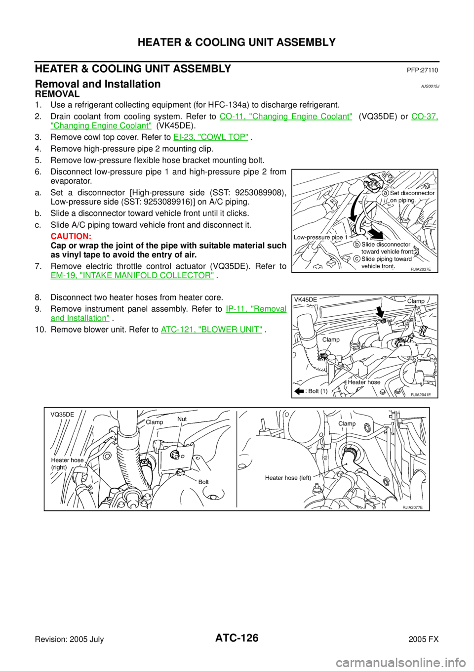
6. Disconnect low-pressure pipe 1 and high-pressure pipe 2 from evaporator.
a. Set a disconnector [High-pressure side (SST: 9253089908), Low-pressure side (SST: 9253089916)] on A/C piping.
b. Slide a disconnector toward vehicle front until it clicks.
c. Slide A/C piping toward vehicle front and disconnect it. CAUTION:
Cap or wrap the joint of the pipe with suitable material such
as vinyl tape to avoid the entry of air.
7. Remove electric throttle control actuator (VQ35DE). Refer to EM-19, "
INTAKE MANIFOLD COLLECTOR" .
8. Disconnect two heater hoses from heater core.
9. Remove instrument panel assembly. Refer to IP-11, "
Removal
and Installation" .
10. Remove blower unit. Refer to ATC-121, "
BLOWER UNIT" .
RJIA2037E
RJIA2041E
RJIA2077E
Page 565 of 4731
ATC-128
HEATER & COOLING UNIT ASSEMBLY
Revision: 2005 July 2005 FX
�When recharging refrigerant, check for leaks.
NOTE:
�When filling radiator with coolant, refer to CO-11, "Changing Engine Coolant" (VQ35DE) or CO-37,
"Changing Engine Coolant" (VK45DE).
�Recharge the refrigerant.
Heater & cooling unit mounting bolt
Tightening torque : 6.8 N·m (0.69 kg-m, 60 in-lb)
Steering member mounting nut and bolt
Tightening torque : 12 N·m (1.2 kg-m, 9 fl-lb)