Page 577 of 4731
ATC-140
REFRIGERANT LINES
Revision: 2005 July 2005 FX
ComponentsAJS0015Q
Refer to AT C - 8 , "Precautions for Refrigerant Connection" .
VQ35DE
RJIA2057E
Page 578 of 4731
REFRIGERANT LINES ATC-141
C
D E
F
G H
I
K L
M A
B
AT C
Revision: 2005 July 2005 FX
VK45DE
Removal and Installation of CompressorAJS0015R
REMOVAL
VQ35DE
RJIA2056E
RJIA2245E
Page 579 of 4731
ATC-142
REFRIGERANT LINES
Revision: 2005 July 2005 FX
VK45DE
1. Use a refrigerant collecting equipment (for HFC-134a) to discharge the refrigerant.
2. Remove air cleaner case and air duct. Refer to EM-17, "
AIR CLEANER AND AIR DUCT" (VQ35DE) or
EM-176, "
AIR CLEANER AND AIR DUCT" (VK45DE).
3. Remove front engine undercover, using power tools.
4. Remove cooling fan shroud (lower). Refer to CO-41, "
RADIATOR" (VK45DE).
5. Remove mounting nuts from low-pressure flexible hose and high-pressure flexible hose.
CAUTION:
Cap or wrap the joint of the pipe with suitable material such
as vinyl tape to avoid the entry of air.
6. Remove high-pressure flexible hose. Refer to ATC-149,
"Removal and Installation of High-Pressure Flexible Hose"
(VK45DE).
7. Disconnect compressor connector.
8. Remove A/C compressor belt. Refer to EM-15, "
DRIVE BELTS" (VQ35DE) or EM-173, "DRIVE BELTS"
(VK45DE).
RJIA2244E
RJIA2059E
RJIA2058E
Page 585 of 4731

ATC-148
REFRIGERANT LINES
Revision: 2005 July 2005 FX
Removal and Installation of Low-Pressure Flexible HoseAJS001BG
REMOVAL
1. Use a refrigerant collecting equipment (for HFC-134a) to discharge the refrigerant.
2. Remove the air cleaner case and air duct. Refer to EM-17, "
AIR CLEANER AND AIR DUCT" (VQ35DE)
or EM-176, "
AIR CLEANER AND AIR DUCT" (VK45DE).
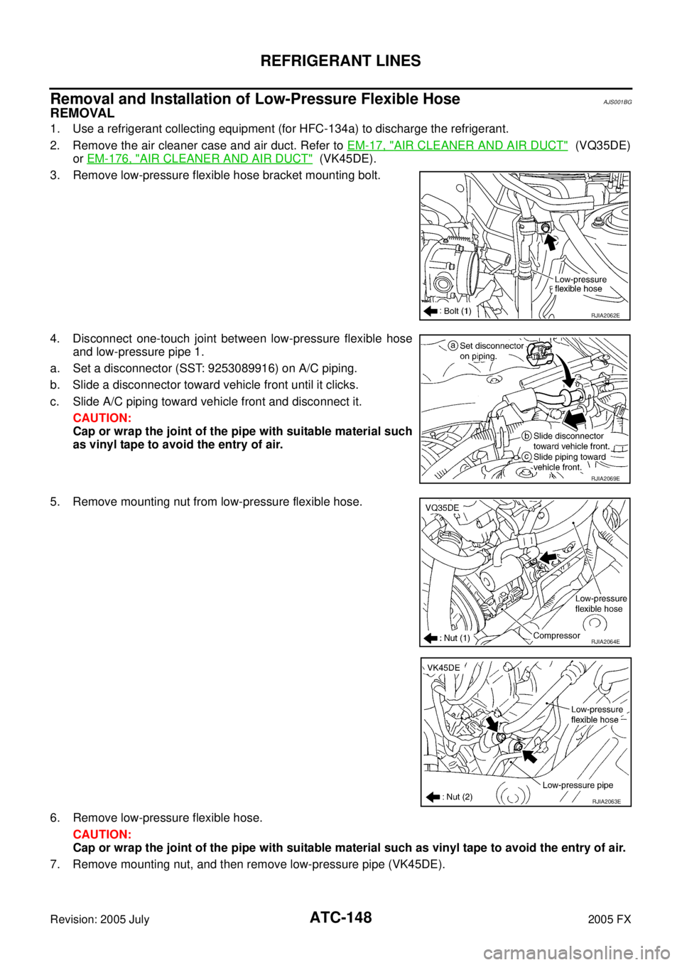
3. Remove low-pressure flexible hose bracket mounting bolt.
4. Disconnect one-touch joint between low-pressure flexible hose and low-pressure pipe 1.
a. Set a disconnector (SST: 9253089916) on A/C piping.
b. Slide a disconnector toward vehicle front until it clicks.
c. Slide A/C piping toward vehicle front and disconnect it. CAUTION:
Cap or wrap the joint of the pipe with suitable material such
as vinyl tape to avoid the entry of air.
5. Remove mounting nut from low-pressure flexible hose.
6. Remove low-pressure flexible hose. CAUTION:
Cap or wrap the joint of the pipe with suitable material such as vinyl tape to avoid the entry of air.
7. Remove mounting nut, and then remove low-pressure pipe (VK45DE).
RJIA2062E
RJIA2069E
RJIA2064E
RJIA2063E
Page 586 of 4731

REFRIGERANT LINES ATC-149
C
D E
F
G H
I
K L
M A
B
AT C
Revision: 2005 July 2005 FX
INSTALLATION
Installation is basically the reverse order of removal.
CAUTION:
�Replace O-rings of A/C piping with new ones, and then apply compressor oil to it when installing
it.
�Connection point for female-side piping is thin. So, when inserting male-side piping, take care not
to deform female-side piping. Slowly insert in axial direction.
�Insert one-touch joint connection point securely until it clicks.
�After piping has been connected, pull male-side piping by hand to make sure piping does not
come off.
�When recharging refrigerant, check for leaks.
Removal and Installation of High-Pressure Flexible HoseAJS0015U
REMOVAL
1. Use a refrigerant collecting equipment (for HFC-134a) to discharge the refrigerant.
2. Remove air cleaner case and air duct. Refer to EM-17, "
AIR CLEANER AND AIR DUCT" (VQ35DE) or
EM-176, "
AIR CLEANER AND AIR DUCT" (VK45DE).
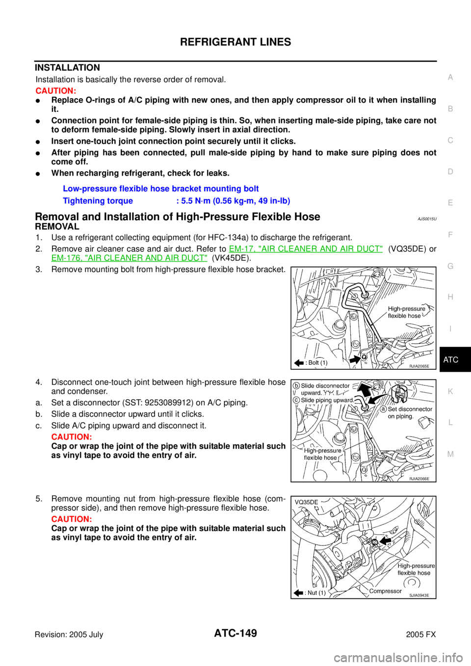
3. Remove mounting bolt from high-pressure flexible hose bracket.
4. Disconnect one-touch joint between high-pressure flexible hose and condenser.
a. Set a disconnector (SST: 9253089912) on A/C piping.
b. Slide a disconnector upward until it clicks.
c. Slide A/C piping upward and disconnect it. CAUTION:
Cap or wrap the joint of the pipe with suitable material such
as vinyl tape to avoid the entry of air.
5. Remove mounting nut from high-pressure flexible hose (com- pressor side), and then remove high-pressure flexible hose.
CAUTION:
Cap or wrap the joint of the pipe with suitable material such
as vinyl tape to avoid the entry of air. Low-pressure flexible hose bracket mounting bolt
Tightening torque : 5.5 N·m (0.56 kg-m, 49 in-lb)
RJIA2065E
RJIA2066E
SJIA0943E
Page 592 of 4731

REFRIGERANT LINES ATC-155
C
D E
F
G H
I
K L
M A
B
AT C
Revision: 2005 July 2005 FX
Removal and Installation of CondenserAJS0015Z
REMOVAL
1. Use a refrigerant collecting equipment (for HFC-134a) to discharge the refrigerant.
2. Remove the air cleaner case and air duct. Refer to EM-17, "
AIR CLEANER AND AIR DUCT" (VQ35DE)
or EM-176, "
AIR CLEANER AND AIR DUCT" (VK45DE).
3. Remove engine undercover, using power tools.
4. Drain engine coolant (VK45DE). Refer to CO-37, "
Changing Engine Coolant" .
5. Remove cooling fan shroud after removing radiator upper hose (VK45DE). Refer to CO-41, "
RADIATOR" .
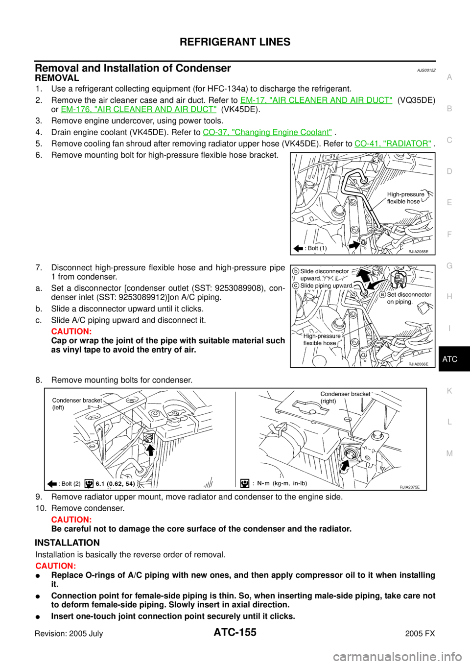
6. Remove mounting bolt for high-pressure flexible hose bracket.
7. Disconnect high-pressure flexible hose and high-pressure pipe 1 from condenser.
a. Set a disconnector [condenser outlet (SST: 9253089908), con- denser inlet (SST: 9253089912)]on A/C piping.
b. Slide a disconnector upward until it clicks.
c. Slide A/C piping upward and disconnect it.
CAUTION:
Cap or wrap the joint of the pipe with suitable material such
as vinyl tape to avoid the entry of air.
8. Remove mounting bolts for condenser.
9. Remove radiator upper mount, move radiator and condenser to the engine side.
10. Remove condenser. CAUTION:
Be careful not to damage the core surface of the condenser and the radiator.
INSTALLATION
Installation is basically the reverse order of removal.
CAUTION:
�Replace O-rings of A/C piping with new ones, and then apply compressor oil to it when installing
it.
�Connection point for female-side piping is thin. So, when inserting male-side piping, take care not
to deform female-side piping. Slowly insert in axial direction.
�Insert one-touch joint connection point securely until it clicks.
RJIA2065E
RJIA2066E
RJIA2075E
Page 597 of 4731

ATC-160
REFRIGERANT LINES
Revision: 2005 July 2005 FX
CHECKING PROCEDURE
To prevent inaccurate or false readings, make sure there is no refrigerant vapor, shop chemicals, or cigarette
smoke in the vicinity of the vehicle. Perform the leak test in calm area (low air/wind movement) so that the
leaking refrigerant is not dispersed.
1. Stop engine.
2. Connect a suitable A/C manifold gauge set to the A/C service ports.
3. Check if the A/C refrigerant pressure is at least 345 kPa (3.52 kg/cm
2 , 50 psi) above 16 °C (61 °F). If less
than specification, recover/evacuate and recharge the system with the specified amount of refrigerant.
NOTE:
At temperatures below 16 °C (61 °F), leaks may not be detected since the system may not reach 345 kPa
(3.52 kg/cm
2 , 50 psi).
4. Perform the leak test from the high-pressure side (compressor discharge a to evaporator inlet h) to the low-pressure side [evaporator drain hose i to shaft seal o (VK45DE) or n (VQ35DE)]. Refer to ATC-140,
"Components" . Perform a leak check for the following areas carefully. Clean the component to be
checked and move the leak detected probe completely around the connection/component.
Compressor
Check the fitting of high- and low-pressure flexible hoses, relief valve and shaft seal.
Condenser
Check the fitting of high-pressure flexible hose and pipe, refrigerant pressure sensor.
Liquid tank
Check the refrigerant connection.
Service valves
Check all around the service valves. Ensure service valve caps are secured on the service valves (to pre-
vent leaks).
NOTE:
After removing A/C manifold gauge set from service valves, wipe any residue from valves to prevent any
false readings by leak detector.
Cooling unit (Evaporator)
With engine OFF, turn blower fan on “High” for at least 15 seconds to dissipate any refrigerant trace in the
cooling unit. Wait a minimum of 10 minutes accumulation time (refer to the manufacturer’s recommended
procedure for actual wait time) before inserting the leak detector probe into the drain hose.
Keep the probe inserted for at least 10 seconds. Use caution not to contaminate the probe tip with water
or dirt that may be in the drain hose.
5. If a leak detector detects a leak, verify at least once by blowing compressed air into area of suspected leak, then repeat check as outlined above.
6. Do not stop when one leak is found. Continue to check for additional leaks at all system components. If no leaks are found, perform steps 7-10.
7. Start engine.
8. Set the heater A/C control as follows;
a. A/C switch: ON
b. Mode door position: VENT (Ventilation)
c. Intake position: Recirculation
d. Temperature setting: Max cold
e. Fan speed: High
9. Run engine at 1,500 rpm for at least 2 minutes.
10. Stop engine and perform leak check again following steps 4 through 6 above.
Refrigerant leaks should be checked immediately after stopping
the engine. Begin with the leak detector at the compressor. The
pressure on the high-pressure side will gradually drop after
refrigerant circulation stops and pressure on the low-pressure
side will gradually rise, as shown in the graph. Some leaks are
more easily detected when pressure is high.
SHA839E
Page 599 of 4731
ATC-162
SERVICE DATA AND SPECIFICATIONS (SDS)
Revision: 2005 July 2005 FX
SERVICE DATA AND SPECIFICATIONS (SDS)PFP:00030
CompressorAJS00167
LubricantAJS00168
RefrigerantAJS00169
Engine Idling SpeedAJS0016A
Refer to EC-83, "Idle Speed and Ignition Timing Check" (VQ35DE) or EC-774, "Idle Speed and Ignition Tim-
ing Check" (VK45DE).
Belt TensionAJS0016B
Refer to EM-15, "DRIVE BELTS" (VQ35DE) or EM-173, "DRIVE BELTS" (VK45DE).
Model Calsonic Kansei make CWV-618
Ty p e V-6 variable displacement
Displacement
cm
3 (cu in)/rev Max. 184 (11.228)
Min. 14.5 (0.885)
Cylinder bore × stroke
mm (in) 37 (1.46)
× [2.3 - 28.6 (0.091 - 1.126)]
Direction of rotation Clockwise (viewed from drive end)
Drive belt Poly V
ModelCalsonic Kansei make CWV-618
Name Nissan A/C System Oil Type S (DH-PS)
Part number KLH00-PAGS0
Capacity
m (US fl oz, lmp fl oz) Total in system 180 (6.0, 6.3)
Compressor (Service part) charg-
ing amount 180 (6.0, 6.3)
Ty p e
HFC-134a (R-134a)
Capacity
kg (lb) 0.55 (1.21)