Page 891 of 4731
BL-76
REMOTE KEYLESS ENTRY SYSTEM
Revision: 2005 July 2005 FX
CHECK BACK DOOR SWITCH
1. CHECK BACK DOOR SWITCH INPUT SIGNAL
With CONSULT-II
Check (“BACK DOOR SW”) in “DATA MONITOR” mode with CONSULT-II.
Without CONSULT-II
Check voltage between BCM connector and ground.
OK or NG
OK >> Back door switch circuit is OK.
NG >> GO TO 2.
2. CHECK HARNESS CONTINUITY
1. Turn ignition switch OFF.
2. Disconnect BCM and back door closure motor connector.
3. Check continuity between BCM connector B14 terminal 58 and back door closure motor connector D109 terminal 7.
4. Check continuity between BCM connector B14 terminal 58 and ground.
OK or NG
OK >> GO TO 3.
NG >> Repair or replace harness.
Monitor item Condition DATA MONITOR
BACK DOOR SW OPEN
↓
CLOSE ON
↓
OFF
PIIA2488E
Connector Terminals (Wire color)
Condition Voltage (V)
(Approx.)
(+) (–)
B14 58 (L) Ground OPEN 0
CLOSE 9
PIIA6229E
58 (L) – 7 (L) : Continuity should exist.
58 (L) – Ground : Continuity should not exist.
PIIA6226E
Page 892 of 4731
REMOTE KEYLESS ENTRY SYSTEM BL-77
C
D E
F
G H
J
K L
M A
B
BL
Revision: 2005 July 2005 FX
3. CHECK GROUND CIRCUIT
Check continuity between back door closure motor connector D109
terminal 8 and ground.
OK or NG
OK >> GO TO 4.
NG >> Repair or replace harness.
4. CHECK BACK DOOR SWITCH
Check continuity between back door closure motor D109 terminals 7
and 8.
OK or NG
OK >> GO TO 5.
NG >> Replace back door closure motor.
5. CHECK BCM OUTPUT SIGNAL
1. Connect BCM connector.
2. Check voltage between BCM connector and ground.
OK or NG
OK >> Check condition of harness and connector.
NG >> Replace BCM. 8 (B) – Ground : Continuity should exist.
PIIA6170E
Terminals Back door condition Continuity
78 Open Yes
Close No
PIIA9934E
58 (L) – Ground : Approx. 9V
PIIA6229E
Page 893 of 4731

BL-78
REMOTE KEYLESS ENTRY SYSTEM
Revision: 2005 July 2005 FX
Check Key SwitchAIS004MN
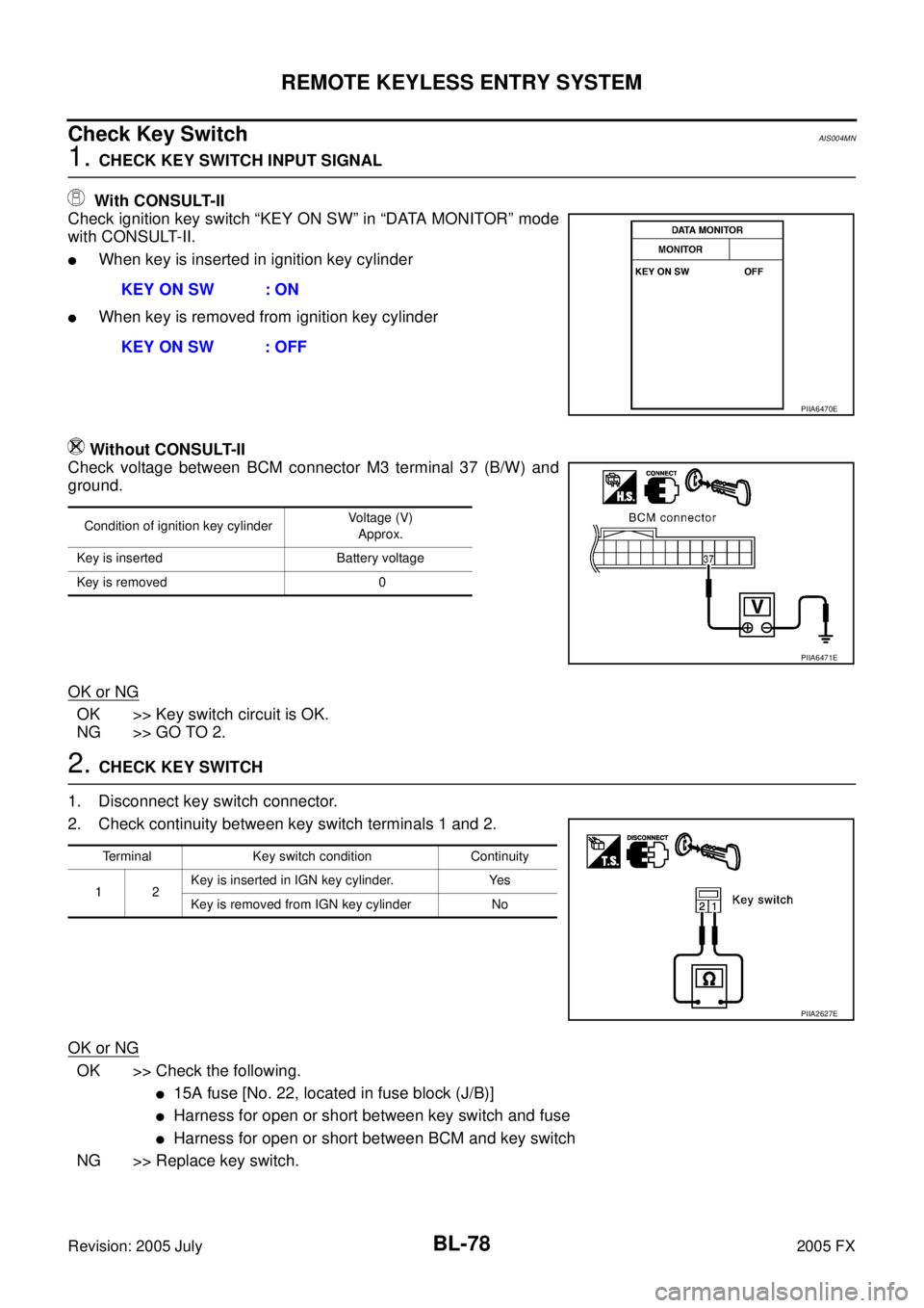
1. CHECK KEY SWITCH INPUT SIGNAL
With CONSULT-II
Check ignition key switch “KEY ON SW” in “DATA MONITOR” mode
with CONSULT-II.
�When key is inserted in ignition key cylinder
�When key is removed from ignition key cylinder
Without CONSULT-II
Check voltage between BCM connector M3 terminal 37 (B/W) and
ground.
OK or NG
OK >> Key switch circuit is OK.
NG >> GO TO 2.
2. CHECK KEY SWITCH
1. Disconnect key switch connector.
2. Check continuity between key switch terminals 1 and 2.
OK or NG
OK >> Check the following.
�15A fuse [No. 22, located in fuse block (J/B)]
�Harness for open or short between key switch and fuse
�Harness for open or short between BCM and key switch
NG >> Replace key switch. KEY ON SW : ON
KEY ON SW : OFF
PIIA6470E
Condition of ignition key cylinder Voltage (V)
Approx.
Key is inserted Battery voltage
Key is removed 0
PIIA6471E
Terminal Key switch condition Continuity
12 Key is inserted in IGN key cylinder. Yes
Key is removed from IGN key cylinder No
PIIA2627E
Page 894 of 4731
REMOTE KEYLESS ENTRY SYSTEM BL-79
C
D E
F
G H
J
K L
M A
B
BL
Revision: 2005 July 2005 FX
Check Remote Keyless Entry ReceiverAIS0069Y
1. CHECK REMOTE KEYLESS ENTRY RECEIVER OUTPUT SIGNAL
1. Turn ignition switch OFF.
2. Check remote keyless entry receiver connector M78 terminal 2 (L) and ground signal with oscilloscope.
OK or NG
OK >> Remote keyless entry receiver circuit is OK.
NG >> GO TO 2.
2. CHECK REMOTE KEYLESS ENTRY RECEIVER INPUT VOLTAGE
1. Disconnect remote keyless entry receiver connector.
2. Check voltage between remote keyless entry receiver connector M78 terminal 4 (R) and ground.
OK or NG
OK >> GO TO 4.
NG >> GO TO 3.
Connector Terminal
(Wire color) Condition
of keyfob Voltag e
(Reference value)
(+) (–)
M78 2 Ground No function
Any button is pressed
PIIB1375E
OCC3879D
OCC3880D
4 (Y) – Ground : Approx. 4.5V
PIIB3953E
Page 897 of 4731
BL-82
REMOTE KEYLESS ENTRY SYSTEM
Revision: 2005 July 2005 FX
Check IPDM E/R OperationAIS004MO
1. CHECK IPDM E/R INPUT VOLTAGE
Check voltage between IPDM E/R connector E9 terminal 51 and
ground.
OK or NG
OK >> Replace IPDM E/R.
NG >> GO TO 2.
2. CHECK IPDM E/R HARNESS
1. Turn ignition switch OFF.
2. Disconnect IPDM E/R and horn relay connector.
3. Check continuity between IPDM E/R connector E9 terminal 51 and horn relay connector E10 terminal 1.
OK or NG
OK >> Check harness connection.
NG >> Repair or replace harness. 51 (SB) – Ground : Battery voltage
PIIA6403E
51 (SB) – 1 (SB) : Continuity should exist.
PIIA6404E
Page 898 of 4731

REMOTE KEYLESS ENTRY SYSTEM BL-83
C
D E
F
G H
J
K L
M A
B
BL
Revision: 2005 July 2005 FX
Check Hazard Warning Lamp FunctionAIS004MP
1. CHECK HAZARD WARNING LAMP
Do hazard warning lamp flash with hazard switch?
YES or NO
YES >> Hazard warning lamp circuit is OK.
NO >> Check hazard circuit. Refer to LT- 9 1 , "
TURN SIGNAL AND HAZARD WARNING LAMPS" .
Check Horn FunctionAIS004MQ
First perform the “SELF-DIAG RESULTS” in “BCM” with CONSULT-II, then perform the trouble diagnosis of
malfunction system indicated “SELF-DIAG RESULTS” of “BCM”. Refer to BCS-15, "
CAN Communication
Inspection Using CONSULT-II (Self-Diagnosis)" .
1. CHECK HORN FUNCTION
Does horn sound with horn switch?
YES or NO
YES >> Horn circuit is OK.
NO >> Check horn circuit. Refer to WW-59, "
HORN" .
Check Headlamp FunctionAIS004MR
First perform the “SELF-DIAG RESULTS” in “BCM” with CONSULT-II, then perform the trouble diagnosis of
malfunction system indicated “SELF-DIAG RESULTS” of “BCM”. Refer to BCS-15, "
CAN Communication
Inspection Using CONSULT-II (Self-Diagnosis)" .
1. CHECK HEADLAMP FUNCTION
Does headlamp come on when turning lighting switch “ON”?
YES or NO
YES >> Headlamp operation circuit is OK.
NO >> Check headlamp system. Refer to LT- 7 , "
HEADLAMP - XENON TYPE -" .
Check Map Lamp and Ignition Keyhole Illumination FunctionAIS004MS
1. CHECK MAP LAMP AND IGNITION KEYHOLE ILLUMINATION FUNCTION
When map lamp switch is in “DOOR” position, open the front door (LH or RH).
OK or NG
OK >> Replace BCM.
NG >> Check ignition illumination circuit. Refer to LT- 1 5 9 , "
INTERIOR ROOM LAMP" .
Map lamp and ignition keyhole illumination should illuminate.
Page 899 of 4731

BL-84
REMOTE KEYLESS ENTRY SYSTEM
Revision: 2005 July 2005 FX
ID Code Entry ProcedureAIS004MT
KEY FOB ID SET UP WITH CONSULT-II
NOTE:
�If a key fob is lost, the ID code of the lost key fob must be erased to prevent unauthorized use. A
specific ID code can be erased with CONSULT-II. However, when the ID code of a lost key fob is not
known, all controller ID codes should be erased. After all ID codes are erased, the ID codes of all
remaining and/or new key fobs must be re-registered.
�When registering an additional key fob, the existing ID codes in memory may or may not be
erased. If four ID codes are stored in memory, when an additional code is registered, only the old-
est code is erased. If less than five ID codes are stored in memory, when an additional ID code is
registered, the new ID code is added and no ID codes are erased.
�Entry of maximum five ID codes is allowed. When more than four ID codes are entered, the oldest
ID code will be erased.
�Even if same ID code that is already in the memory is input, the same ID code can be entered. The
code is counted as an additional code.
CAUTION:
If CONSULT-II is used with no connection of CONSULT-II CONVERTER, malfunctions might be
detected in self-diagnosis depending on control unit which carry out CAN communication.
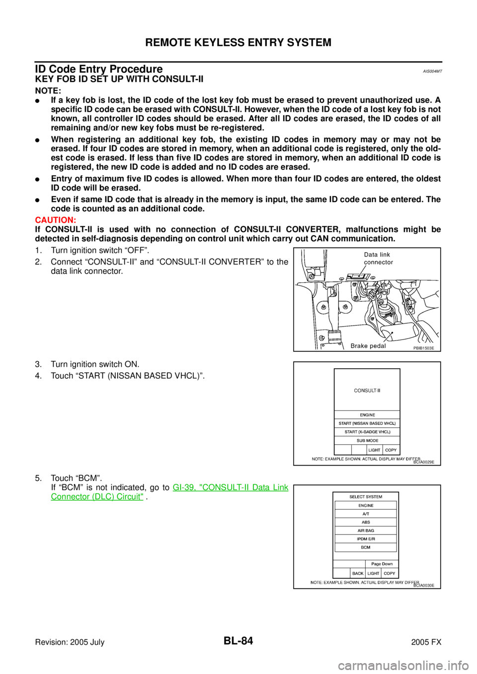
1. Turn ignition switch “OFF”.
2. Connect “CONSULT-II” and “CONSULT-II CONVERTER” to the data link connector.
3. Turn ignition switch ON.
4. Touch “START (NISSAN BASED VHCL)”.
5. Touch “BCM”. If “BCM” is not indicated, go to GI-39, "
CONSULT-II Data Link
Connector (DLC) Circuit" .
PBIB1503E
BCIA0029E
BCIA0030E
Page 906 of 4731

INTELLIGENT KEY SYSTEM BL-91
C
D E
F
G H
J
K L
M A
B
BL
Revision: 2005 July 2005 FXSystem DescriptionAIS004MW
�The Intelligent Key system is a system which can lock and unlock the doors (door lock function) and start
the engine (engine start function) by carrying around the Intelligent Key, which operates based on the
results of electrical key-ID verification using two-way communications between the Intelligent Key and the
vehicle
�Operation of the remote control buttons on the Intelligent Key also provides the same functions as the
remote control entry system. (Remote control entry functions)
�As an ignition key warning function, when a door is locked or unlocked with entry switch or remote control-
ler button operation, the hazard lamps flash and the Intelligent Key warning buzzer sounds.
�Even if the vehicle or Intelligent Key battery runs down, the door can be locked and unlocked and the
engine started with the mechanical key built into the Intelligent Key.
�If an Intelligent Key was lost, a new Intelligent Key can be registered. A maximum of 4 Intelligent Keys can
be registered.
�It has been made possible to diagnose the system, change the function setting and register an Intelligent
Key with the CONSULT-II.
DOOR LOCK FUNCTION
Operation Description
�When the driver door, passenger door, or back door request switch is pressed, Intelligent Key unit sends a
request signal from the transmission antenna corresponding to the pressed door request switch, key-ID
verification is performed using two-way communication with Intelligent Key, and if ID is successfully veri-
fied, a door lock/unlock request signal is sent to BCM (Body Control Module) using CAN communication
to lock/unlock the door lock.
�When door is locking, door is unlocked, when door is unlocking, door is locked.
�When door is locked/unlocked by door request switch operation, hazard lamps flash and Intelligent Key
warning buzzer sounds.
�With the locking operation of door request switch, door lock actuators of all door are locked.
PIIB4645E