Page 1995 of 4731
![INFINITI FX35 2005 Service Manual EC-602
[VQ35DE]
DTC P1572 ASCD BRAKE SWITCH
Revision: 2005 July 2005 FX
3. CHECK ASCD BRAKE SWITCH POWER SUPPLY CIRCUIT
1. Turn ignition switch OFF.
2. Disconnect ASCD brake switch harness connector](/manual-img/42/57020/w960_57020-1994.png "INFINITI FX35 2005 Service Manual EC-602
[VQ35DE]
DTC P1572 ASCD BRAKE SWITCH
Revision: 2005 July 2005 FX
3. CHECK ASCD BRAKE SWITCH POWER SUPPLY CIRCUIT
1. Turn ignition switch OFF.
2. Disconnect ASCD brake switch harness connector")
EC-602
[VQ35DE]
DTC P1572 ASCD BRAKE SWITCH
Revision: 2005 July 2005 FX
3. CHECK ASCD BRAKE SWITCH POWER SUPPLY CIRCUIT
1. Turn ignition switch OFF.
2. Disconnect ASCD brake switch harness connector.
3. Turn ignition switch ON.
4. Check voltage between ASCD brake switch terminal 1 and ground with CONSULT-II or tester.
OK or NG
OK >> GO TO 5.
NG >> GO TO 4.
4. DETECT MALFUNCTIONING PART
Check the following.
�Fuse block (J/B) connector E201
�10A fuse
�Harness for open or short between ASCD brake switch and fuse
>> Repair open circuit or short to ground or short to power in harness or connectors.
5. CHECK ASCD BRAKE SWITCH INPUT SIGNAL CIRCUIT FOR OPEN AND SHORT
1. Turn ignition switch OFF.
2. Disconnect ECM harness connector.
3. Check harness continuity between ECM terminal 108 and ASCD brake switch terminal 2. Refer to Wiring Diagram.
4. Also check harness for short to ground and short to power.
OK or NG
OK >> GO TO 7.
NG >> GO TO 6.
6. DETECT MALFUNCTIONING PART
Check the following.
�Harness connectors E211, M41
�Harness for open or short between ECM and ASCD brake switch
>> Repair open circuit or short to ground or short to power in harness or connectors.
PBIB1605E
Voltage: Battery voltage
PBIB0857E
Continuity should exist.
Page 1996 of 4731
![INFINITI FX35 2005 Service Manual DTC P1572 ASCD BRAKE SWITCH EC-603
[VQ35DE]
C
D E
F
G H
I
J
K L
M A
EC
Revision: 2005 July 2005 FX
7. CHECK ASCD BRAKE SWITCH
Refer to EC-604, "
Component Inspection"
OK or NG
OK >>](/manual-img/42/57020/w960_57020-1995.png "INFINITI FX35 2005 Service Manual DTC P1572 ASCD BRAKE SWITCH EC-603
[VQ35DE]
C
D E
F
G H
I
J
K L
M A
EC
Revision: 2005 July 2005 FX
7. CHECK ASCD BRAKE SWITCH
Refer to EC-604, \"
Component Inspection\"
OK or NG
OK >>")
DTC P1572 ASCD BRAKE SWITCH EC-603
[VQ35DE]
C
D E
F
G H
I
J
K L
M A
EC
Revision: 2005 July 2005 FX
7. CHECK ASCD BRAKE SWITCH
Refer to EC-604, "
Component Inspection"
OK or NG
OK >> GO TO 13.
NG >> Replace ASCD brake switch.
8. CHECK STOP LAMP SWITCH POWER SUPPLY CIRCUIT
1. Turn ignition switch OFF.
2. Disconnect stop lamp switch harness connector.
3. Check voltage between stop lamp switch terminal 1 and ground with CONSULT-II or tester.
OK or NG
OK >> GO TO 10.
NG >> GO TO 9.
9. DETECT MALFUNCTIONING PART
Check the following.
�Fuse block (J/B) connector E201
�10A fuse
�Harness for open or short between stop lamp switch and battery
>> Repair open circuit or short to ground or short to power in harness or connectors.
10. CHECK STOP LAMP SWITCH INPUT SIGNAL CIRCUIT FOR OPEN AND SHORT
1. Disconnect ECM harness connector.
2. Check harness continuity between ECM terminal 101 and stop lamp switch terminal 2. Refer to Wiring Diagram.
3. Also check harness for short to ground and short to power.
OK or NG
OK >> GO TO 12.
NG >> GO TO 11.
PBIB1605E
Voltage: Battery voltage
PBIB1184E
Continuity should exist.
Page 2010 of 4731
![INFINITI FX35 2005 Service Manual DTC P1805 BRAKE SWITCH EC-617
[VQ35DE]
C
D E
F
G H
I
J
K L
M A
EC
Revision: 2005 July 2005 FX
3. DETECT MALFUNCTIONING PART
Check the following.
�10A fuse
�Fuse block (J/B) connector E20](/manual-img/42/57020/w960_57020-2009.png "INFINITI FX35 2005 Service Manual DTC P1805 BRAKE SWITCH EC-617
[VQ35DE]
C
D E
F
G H
I
J
K L
M A
EC
Revision: 2005 July 2005 FX
3. DETECT MALFUNCTIONING PART
Check the following.
�10A fuse
�Fuse block (J/B) connector E20")
DTC P1805 BRAKE SWITCH EC-617
[VQ35DE]
C
D E
F
G H
I
J
K L
M A
EC
Revision: 2005 July 2005 FX
3. DETECT MALFUNCTIONING PART
Check the following.
�10A fuse
�Fuse block (J/B) connector E201
�Harness for open and short between stop lamp switch and battery
>> Repair open circuit or short to ground or short to power in harness or connectors.
4. CHECK STOP LAMP SWITCH INPUT SIGNAL CIRCUIT FOR OPEN AND SHORT
1. Turn ignition switch OFF.
2. Disconnect ECM harness connector.
3. Disconnect stop lamp switch harness connector.
4. Check harness continuity between ECM terminal 101 and stop lamp switch terminal 2.
Refer to Wiring Diagram.
5. Also check harness for short to ground and short to power.
OK or NG
OK >> GO TO 6.
NG >> GO TO 5.
5. DETECT MALFUNCTIONING PART
Check the following.
�Harness connectors E211, M41
�Harness for open or short between ECM and stop lamp switch
>> Repair open circuit or short to ground or short to power in harness or connectors.
6. CHECK STOP LAMP SWITCH
Refer to EC-618, "
Component Inspection" .
OK or NG
OK >> GO TO 7.
NG >> Replace stop lamp switch.
7. CHECK INTERMITTENT INCIDENT
Refer to EC-163, "
TROUBLE DIAGNOSIS FOR INTERMITTENT INCIDENT" .
>> INSPECTION END
Continuity should exist.
PBIB1605E
Page 2052 of 4731
![INFINITI FX35 2005 Service Manual IGNITION SIGNAL EC-659
[VQ35DE]
C
D E
F
G H
I
J
K L
M A
EC
Revision: 2005 July 2005 FX
Component InspectionABS006Y7
IGNITION COIL WITH POWER TRANSISTOR
CAUTION:
Do the following procedur](/manual-img/42/57020/w960_57020-2051.png "INFINITI FX35 2005 Service Manual IGNITION SIGNAL EC-659
[VQ35DE]
C
D E
F
G H
I
J
K L
M A
EC
Revision: 2005 July 2005 FX
Component InspectionABS006Y7
IGNITION COIL WITH POWER TRANSISTOR
CAUTION:
Do the following procedur")
IGNITION SIGNAL EC-659
[VQ35DE]
C
D E
F
G H
I
J
K L
M A
EC
Revision: 2005 July 2005 FX
Component InspectionABS006Y7
IGNITION COIL WITH POWER TRANSISTOR
CAUTION:
Do the following procedure in the place where ventilation is good without the combustible.
1. Turn ignition switch OFF.
2. Disconnect ignition coil harness connector.
3. Check resistance between ignition coil terminals as follows.
4. If NG, Replace ignition coil with power transistor. If OK, go to next step.
5. Turn ignition switch OFF.
6. Reconnect all harness connectors disconnected.
7. Remove fuel pump fuse in IPDM E/R to release fuel pressure.
NOTE:
Do not use CONSULT-II to release fuel pressure, or fuel pres-
sure applies again during the following procedure.
8. Start engine.
9. After engine stalls, crank it 2 or 3 times to release all fuel pres- sure.
10. Turn ignition switch OFF.
11. Remove ignition coil harness connectors to avoid the electrical discharge from the ignition coils.
12. Remove ignition coil and spark plug of the cylinder to be checked.
13. Crank engine for 5 seconds or more to remove combustion gas in the cylinder.
14. Connect spark plug and harness connector to ignition coil.
15. Fix ignition coil using a rope etc. with gap of 13 - 17 mm between the edge of the spark plug and grounded metal portion
as shown in the figure.
16. Crank engine for about three seconds, and check whether spark is generated between the spark plug and the grounded part.
CAUTION:
�Do not approach to the spark plug and the ignition coil
within 50cm. Be careful not to get an electrical shock
while checking, because the electrical discharge voltage
becomes 20kV or more.
�It might cause to damage the ignition coil if the gap of 17 mm or more is taken.
NOTE:
When the gap is 13 mm or less, the spark might be generated even if the coil is malfunctioning.
17. If NG, Replace ignition coil with power transistor.
Terminal No. (Polarity) Resistance Ω [at 25 °C (77 °F)]
1 and 2 Except 0 or ∞
1 and 3 Except 0
2 and 3
Spark should be generated.
PBIB0847E
PBIB1603E
PBIB2325E
Page 2057 of 4731
![INFINITI FX35 2005 Service Manual EC-664
[VQ35DE]
INJECTOR CIRCUIT
Revision: 2005 July 2005 FX
3. CHECK FUNCTION OF INJECTOR-I
With out CONSULT-II
1. Turn ignition switch OFF.
2. Disconnect harness connector F50, F251
3. Turn ignit](/manual-img/42/57020/w960_57020-2056.png "INFINITI FX35 2005 Service Manual EC-664
[VQ35DE]
INJECTOR CIRCUIT
Revision: 2005 July 2005 FX
3. CHECK FUNCTION OF INJECTOR-I
With out CONSULT-II
1. Turn ignition switch OFF.
2. Disconnect harness connector F50, F251
3. Turn ignit")
EC-664
[VQ35DE]
INJECTOR CIRCUIT
Revision: 2005 July 2005 FX
3. CHECK FUNCTION OF INJECTOR-I
With out CONSULT-II
1. Turn ignition switch OFF.
2. Disconnect harness connector F50, F251
3. Turn ignition switch ON.
4. Check voltage between harness connector F50 terminal 5 and ground with CONSULT-II or tester.
5. Turn ignition switch OFF.
6. Disconnect ECM harness connector.
7. Check harness continuity between harness connector F50 and ECM as follows.
Refer to Wiring Diagram.
8. Also check harness for short to ground and short to power.
OK or NG
OK >> GO TO 5.
NG >> GO TO 4.
4. DETECT MALFUNCTIONING PART
Check the following.
�Harness connectors M82, F102
�Harness connectors F50, F251
�Fuse block (J/B) connector M4
�15A fuse
�Harness for open or short between harness connector F50 and fuse
�Harness for open or short between harness connector F50 and ECM
>> Repair open circuit or short to ground or short to power in harness or connectors.
PBIB2624E
Voltage: Battery voltage
Cylinder Harness connector F50
terminal ECM terminal
1623
2442
3222
4341
5121
6740
Continuity should exist.
PBIB2323E
Page 2059 of 4731
![INFINITI FX35 2005 Service Manual EC-666
[VQ35DE]
INJECTOR CIRCUIT
Revision: 2005 July 2005 FX
7. DETECT MALFUNCTIONING PART
Check the following.
�Harness connectors M82, F102
�Harness connectors F50, F251
�Fuse block (J/B) connector](/manual-img/42/57020/w960_57020-2058.png "INFINITI FX35 2005 Service Manual EC-666
[VQ35DE]
INJECTOR CIRCUIT
Revision: 2005 July 2005 FX
7. DETECT MALFUNCTIONING PART
Check the following.
�Harness connectors M82, F102
�Harness connectors F50, F251
�Fuse block (J/B) connector")
EC-666
[VQ35DE]
INJECTOR CIRCUIT
Revision: 2005 July 2005 FX
7. DETECT MALFUNCTIONING PART
Check the following.
�Harness connectors M82, F102
�Harness connectors F50, F251
�Fuse block (J/B) connector M4
�10A fuse
�Harness for open or short between injector and fuse
>> Repair open circuit or short to ground or short to power in harness or connectors.
8. CHECK INJECTOR OUTPUT SIGNAL CIRCUIT FOR OPEN AND SHORT
1. Turn ignition switch OFF.
2. Disconnect ECM harness connector.
3. Check harness continuity between injector terminal 2 and ECM terminals 21, 22, 23, 40, 41, 42. Refer to Wiring Diagram.
4. Also check harness for short to ground and short to power.
OK or NG
OK >> GO TO 10.
NG >> GO TO 9.
9. DETECT MALFUNCTIONING PART
Check the following.
�Harness connectors F251, F50
�Harness for open or short between injector and ECM
>> Repair open circuit or short to ground or short to power in harness or connectors.
10. CHECK INJECTOR
Refer to EC-667, "
Component Inspection" .
OK or NG
OK >> GO TO 11.
NG >> Replace injector.
11 . CHECK INTERMITTENT INCIDENT
Refer to EC-163, "
TROUBLE DIAGNOSIS FOR INTERMITTENT INCIDENT" .
>> INSPECTION END
Continuity should exist.
Page 2064 of 4731
FUEL PUMP CIRCUIT EC-671
[VQ35DE]
C
D E
F
G H
I
J
K L
M A
EC
Revision: 2005 July 2005 FX
4. DETECT MALFUNCTIONING PART
Check the following.
�Harness connectors E211, M41
�Harness for open or short between IPDM E/R and ECM
>> Repair open circuit or short to ground or short to power in harness or connectors.
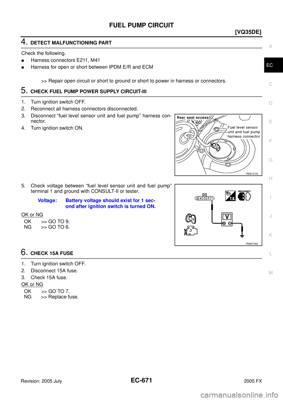
5. CHECK FUEL PUMP POWER SUPPLY CIRCUIT-III
1. Turn ignition switch OFF.
2. Reconnect all harness connectors disconnected.
3. Disconnect “fuel level sensor unit and fuel pump” harness con- nector.
4. Turn ignition switch ON.
5. Check voltage between “fuel level sensor unit and fuel pump” terminal 1 and ground with CONSULT-II or tester.
OK or NG
OK >> GO TO 9.
NG >> GO TO 6.
6. CHECK 15A FUSE
1. Turn ignition switch OFF.
2. Disconnect 15A fuse.
3. Check 15A fuse.
OK or NG
OK >> GO TO 7.
NG >> Replace fuse.
PBIB1572E
Voltage: Battery voltage should exist for 1 sec-
ond after ignition switch is turned ON.
PBIB0795E
Page 2078 of 4731
![INFINITI FX35 2005 Service Manual ICC BRAKE SWITCH EC-685
[VQ35DE]
C
D E
F
G H
I
J
K L
M A
EC
Revision: 2005 July 2005 FX
6. DETECT MALFUNCTIONING PART
Check the following.
�Fuse block (J/B) connector E201
�10A fuse
�Har](/manual-img/42/57020/w960_57020-2077.png "INFINITI FX35 2005 Service Manual ICC BRAKE SWITCH EC-685
[VQ35DE]
C
D E
F
G H
I
J
K L
M A
EC
Revision: 2005 July 2005 FX
6. DETECT MALFUNCTIONING PART
Check the following.
�Fuse block (J/B) connector E201
�10A fuse
�Har")
ICC BRAKE SWITCH EC-685
[VQ35DE]
C
D E
F
G H
I
J
K L
M A
EC
Revision: 2005 July 2005 FX
6. DETECT MALFUNCTIONING PART
Check the following.
�Fuse block (J/B) connector E201
�10A fuse
�Harness for open or short between ICC brake switch and fuse
>> Repair open circuit or short to ground or short to power in harness or connectors.
7. CHECK ICC BRAKE SWITCH INPUT SIGNAL CIRCUIT FOR OPEN AND SHORT-I
1. Turn ignition switch OFF.
2. Check harness continuity between ICC brake hold relay terminal 3 and ICC brake switch terminal 2. Refer to Wiring Diagram.
3. Also check harness for short to ground and short to power.
OK or NG
OK >> GO TO 8.
NG >> Repair open circuit or short to ground or short to power in harness or connectors.
8. CHECK ICC BRAKE SWITCH
Refer to EC-687, "
Component Inspection" .
OK or NG
OK >> GO TO 17.
NG >> Replace ICC brake switch.
9. CHECK ICC BRAKE SWITCH INPUT SIGNAL CIRCUIT FOR OPEN AND SHORT-II
1. Turn ignition switch OFF.
2. Disconnect ECM harness connector.
3. Check harness continuity between ICC brake hold relay terminal 4 and ECM terminal 108. Refer Wiring Diagram.
4. Also check harness for short to ground and short to power.
OK or NG
OK >> GO TO 11.
NG >> GO TO 10.
10. DETECT MALFUNCTIONING PART
Check the following.
�Harness connectors E211, M41
�Harness for open or short between ICC brake hold relay and ECM
>> Repair open circuit or short to ground or short to power in harness or connectors.
11 . CHECK ICC BRAKE HOLD RELAY
Refer to EC-687, "
Component Inspection" .
OK >> GO TO 17.
NG >> Replace ICC brake fold relay. Continuity should exist.
Continuity should exist.