Page 2661 of 4731
![INFINITI FX35 2005 Service Manual EC-1268
[VK45DE]
DTC P1572 ICC BRAKE SWITCH
Revision: 2005 July 2005 FX
6. DETECT MALFUNCTIONING PART
Check the following.
�Fuse block (J/B) connector E201
�10A fuse
�Harness for open or short betwee](/manual-img/42/57020/w960_57020-2660.png "INFINITI FX35 2005 Service Manual EC-1268
[VK45DE]
DTC P1572 ICC BRAKE SWITCH
Revision: 2005 July 2005 FX
6. DETECT MALFUNCTIONING PART
Check the following.
�Fuse block (J/B) connector E201
�10A fuse
�Harness for open or short betwee")
EC-1268
[VK45DE]
DTC P1572 ICC BRAKE SWITCH
Revision: 2005 July 2005 FX
6. DETECT MALFUNCTIONING PART
Check the following.
�Fuse block (J/B) connector E201
�10A fuse
�Harness for open or short between ICC brake switch and fuse
>> Repair open circuit or short to ground or short to power in harness or connectors.
7. CHECK ICC BRAKE SWITCH INPUT SIGNAL CIRCUIT FOR OPEN AND SHORT-I
1. Turn ignition switch OFF.
2. Check harness continuity between ICC brake hold relay terminal 3 and ICC brake switch terminal 2. Refer to Wiring Diagram.
3. Also check harness for short to ground and short to power.
OK or NG
OK >> GO TO 8.
NG >> Repair open circuit or short to ground or short to power in harness or connectors.
8. CHECK ICC BRAKE SWITCH
Refer to EC-1270, "
Component Inspection" .
OK or NG
OK >> GO TO 17.
NG >> Replace ICC brake switch.
9. CHECK ICC BRAKE SWITCH INPUT SIGNAL CIRCUIT FOR OPEN AND SHORT-II
1. Turn ignition switch OFF.
2. Disconnect ECM harness connector.
3. Check harness continuity between ICC brake hold relay terminal 4 and ECM terminal 108. Refer Wiring Diagram.
4. Also check harness for short to ground and short to power.
OK or NG
OK >> GO TO 11.
NG >> GO TO 10.
10. DETECT MALFUNCTIONING PART
Check the following.
�Harness connectors E211, M41
�Harness for open or short between ICC brake hold relay and ECM
>> Repair open circuit or short to ground or short to power in harness or connectors.
11 . CHECK ICC BRAKE HOLD RELAY
Refer to EC-1270, "
Component Inspection" .
OK >> GO TO 17.
NG >> Replace ICC brake hold relay. Continuity should exist.
Continuity should exist.
Page 2662 of 4731
![INFINITI FX35 2005 Service Manual DTC P1572 ICC BRAKE SWITCH EC-1269
[VK45DE]
C
D E
F
G H
I
J
K L
M A
EC
Revision: 2005 July 2005 FX
12. CHECK STOP LAMP SWITCH POWER SUPPLY CIRCUIT
1. Turn ignition switch OFF.
2. Discon](/manual-img/42/57020/w960_57020-2661.png "INFINITI FX35 2005 Service Manual DTC P1572 ICC BRAKE SWITCH EC-1269
[VK45DE]
C
D E
F
G H
I
J
K L
M A
EC
Revision: 2005 July 2005 FX
12. CHECK STOP LAMP SWITCH POWER SUPPLY CIRCUIT
1. Turn ignition switch OFF.
2. Discon")
DTC P1572 ICC BRAKE SWITCH EC-1269
[VK45DE]
C
D E
F
G H
I
J
K L
M A
EC
Revision: 2005 July 2005 FX
12. CHECK STOP LAMP SWITCH POWER SUPPLY CIRCUIT
1. Turn ignition switch OFF.
2. Disconnect stop lamp switch harness connector.
3. Check voltage between stop lamp switch terminal 1 and ground with CONSULT -II or tester.
OK or NG
OK >> GO TO 14.
NG >> GO TO 13.
13. DETECT MALFUNCTIONING PART
Check the following.
�Fuse block (J/B) connector E201
�10A fuse
�Harness for open or short between stop lamp switch and battery
>> Repair open circuit or short to ground or short to power in harness or connectors.
14. CHECK STOP LAMP SWITCH INPUT SIGNAL CIRCUIT FOR OPEN AND SHORT
1. Disconnect ECM harness connector.
2. Check harness continuity between ECM terminal 101 and stop lamp switch terminal 2. Refer to Wiring Diagram.
3. Also check harness for short to ground and short to power.
OK or NG
OK >> GO TO 16.
NG >> GO TO 15.
15. DETECT MALFUNCTIONING PART
Check the following.
�Harness connectors E211, M41
�Harness for open or short between ECM and stop lamp switch
>> Repair open circuit or short to ground or short to power in harness or connectors.
PBIB2558E
Voltage: Battery voltage
PBIB1184E
Continuity should exist.
Page 2669 of 4731
![INFINITI FX35 2005 Service Manual EC-1276
[VK45DE]
DTC P1572 ASCD BRAKE SWITCH
Revision: 2005 July 2005 FX
3. CHECK ASCD BRAKE SWITCH POWER SUPPLY CIRCUIT
1. Turn ignition switch OFF.
2. Disconnect ASCD brake switch harness connecto](/manual-img/42/57020/w960_57020-2668.png "INFINITI FX35 2005 Service Manual EC-1276
[VK45DE]
DTC P1572 ASCD BRAKE SWITCH
Revision: 2005 July 2005 FX
3. CHECK ASCD BRAKE SWITCH POWER SUPPLY CIRCUIT
1. Turn ignition switch OFF.
2. Disconnect ASCD brake switch harness connecto")
EC-1276
[VK45DE]
DTC P1572 ASCD BRAKE SWITCH
Revision: 2005 July 2005 FX
3. CHECK ASCD BRAKE SWITCH POWER SUPPLY CIRCUIT
1. Turn ignition switch OFF.
2. Disconnect ASCD brake switch harness connector.
3. Turn ignition switch ON.
4. Check voltage between ASCD brake switch terminal 1 and ground with CONSULT-II or tester.
OK or NG
OK >> GO TO 5.
NG >> GO TO 4.
4. DETECT MALFUNCTIONING PART
Check the following.
�Fuse block (J/B) connector E201
�10A fuse
�Harness for open or short between ASCD brake switch and fuse
>> Repair open circuit or short to ground or short to power in harness or connectors.
5. CHECK ASCD BRAKE SWITCH INPUT SIGNAL CIRCUIT FOR OPEN AND SHORT
1. Turn ignition switch OFF.
2. Disconnect ECM harness connector.
3. Check harness continuity between ECM terminal 108 and ASCD brake switch terminal 2. Refer to Wiring Diagram.
4. Also check harness for short to ground and short to power.
OK or NG
OK >> GO TO 7.
NG >> GO TO 6.
6. DETECT MALFUNCTIONING PART
Check the following.
�Harness connectors E211, M41
�Harness for open or short between ECM and ASCD brake switch
>> Repair open circuit or short to ground or short to power in harness or connectors.
PBIB2558E
Voltage: Battery voltage
PBIB0857E
Continuity should exist.
Page 2670 of 4731
![INFINITI FX35 2005 Service Manual DTC P1572 ASCD BRAKE SWITCH EC-1277
[VK45DE]
C
D E
F
G H
I
J
K L
M A
EC
Revision: 2005 July 2005 FX
7. CHECK ASCD BRAKE SWITCH
Refer to EC-1278, "
Component Inspection"
OK or NG
OK](/manual-img/42/57020/w960_57020-2669.png "INFINITI FX35 2005 Service Manual DTC P1572 ASCD BRAKE SWITCH EC-1277
[VK45DE]
C
D E
F
G H
I
J
K L
M A
EC
Revision: 2005 July 2005 FX
7. CHECK ASCD BRAKE SWITCH
Refer to EC-1278, \"
Component Inspection\"
OK or NG
OK")
DTC P1572 ASCD BRAKE SWITCH EC-1277
[VK45DE]
C
D E
F
G H
I
J
K L
M A
EC
Revision: 2005 July 2005 FX
7. CHECK ASCD BRAKE SWITCH
Refer to EC-1278, "
Component Inspection"
OK or NG
OK >> GO TO 13.
NG >> Replace ASCD brake switch.
8. CHECK STOP LAMP SWITCH POWER SUPPLY CIRCUIT
1. Turn ignition switch OFF.
2. Disconnect stop lamp switch harness connector.
3. Check voltage between stop lamp switch terminal 1 and ground with CONSULT-II or tester.
OK or NG
OK >> GO TO 10.
NG >> GO TO 9.
9. DETECT MALFUNCTIONING PART
Check the following.
�Fuse block (J/B) connector E201
�10A fuse
�Harness for open or short between stop lamp switch and battery
>> Repair open circuit or short to ground or short to power in harness or connectors.
10. CHECK STOP LAMP SWITCH INPUT SIGNAL CIRCUIT FOR OPEN AND SHORT
1. Disconnect ECM harness connector.
2. Check harness continuity between ECM terminal 101 and stop lamp switch terminal 2. Refer to Wiring Diagram.
3. Also check harness for short to ground and short to power.
OK or NG
OK >> GO TO 12.
NG >> GO TO 11.
PBIB2558E
Voltage: Battery voltage
PBIB1184E
Continuity should exist.
Page 2693 of 4731
![INFINITI FX35 2005 Service Manual EC-1300
[VK45DE]
DTC P1805 BRAKE SWITCH
Revision: 2005 July 2005 FX
3. DETECT MALFUNCTIONING PART
Check the following.
�10A fuse
�Fuse block (J/B) connector E201
�Harness for open and short between s](/manual-img/42/57020/w960_57020-2692.png "INFINITI FX35 2005 Service Manual EC-1300
[VK45DE]
DTC P1805 BRAKE SWITCH
Revision: 2005 July 2005 FX
3. DETECT MALFUNCTIONING PART
Check the following.
�10A fuse
�Fuse block (J/B) connector E201
�Harness for open and short between s")
EC-1300
[VK45DE]
DTC P1805 BRAKE SWITCH
Revision: 2005 July 2005 FX
3. DETECT MALFUNCTIONING PART
Check the following.
�10A fuse
�Fuse block (J/B) connector E201
�Harness for open and short between stop lamp switch and battery
>> Repair open circuit or short to ground or short to power in harness or connectors.
4. CHECK STOP LAMP SWITCH INPUT SIGNAL CIRCUIT FOR OPEN AND SHORT
1. Disconnect ECM harness connector.
2. Disconnect stop lamp switch harness connector.
3. Check harness continuity between ECM terminal 101 and stop lamp switch terminal 2. Refer to Wiring Diagram.
4. Also check harness for short to ground and short to power.
OK or NG
OK >> GO TO 6.
NG >> GO TO 5.
5. DETECT MALFUNCTIONING PART
Check the following.
�Harness connectors E211, M41
�Harness for open or short between ECM and stop lamp switch
>> Repair open circuit or short to ground or short to power in harness or connectors.
6. CHECK STOP LAMP SWITCH
Refer to EC-1301, "
Component Inspection" .
OK or NG
OK >> GO TO 7.
NG >> Replace stop lamp switch.
7. CHECK INTERMITTENT INCIDENT
Refer to EC-854, "
TROUBLE DIAGNOSIS FOR INTERMITTENT INCIDENT" .
>> INSPECTION END
Continuity should exist.
Page 2730 of 4731
![INFINITI FX35 2005 Service Manual VARIABLE INDUCTION AIR CONTROL SYSTEM (VIAS) EC-1337
[VK45DE]
C
D E
F
G H
I
J
K L
M A
EC
Revision: 2005 July 2005 FX
7. DETECT MALFUNCTIONING PART
Check the following.
�Harness connector](/manual-img/42/57020/w960_57020-2729.png "INFINITI FX35 2005 Service Manual VARIABLE INDUCTION AIR CONTROL SYSTEM (VIAS) EC-1337
[VK45DE]
C
D E
F
G H
I
J
K L
M A
EC
Revision: 2005 July 2005 FX
7. DETECT MALFUNCTIONING PART
Check the following.
�Harness connector")
VARIABLE INDUCTION AIR CONTROL SYSTEM (VIAS) EC-1337
[VK45DE]
C
D E
F
G H
I
J
K L
M A
EC
Revision: 2005 July 2005 FX
7. DETECT MALFUNCTIONING PART
Check the following.
�Harness connectors E211, M41
�Harness connectors M82, F102
�IPDM E/R connector E7
�10A fuse
�Harness continuity between IPDM E/R and VIAS control solenoid valve
>> Repair open circuit or short to ground or short to power in harness or connectors.
8. CHECK VIAS CONTROL SOLENOID VALVE OUTPUT SIGNAL CIRCUIT FOR OPEN AND SHORT
1. Turn ignition switch OFF.
2. Disconnect ECM harness connector.
3. Check harness continuity between ECM terminal 29 and VIAS control solenoid valve terminal 2. Refer to Wiring Diagram.
4. Also check harness for short to ground and short to power.
OK or NG
OK >> GO TO 9.
NG >> Repair open circuit or short to ground or short to power in harness or connectors.
9. CHECK VIAS CONTROL SOLENOID VALVE
Refer to EC-1337, "
Component Inspection" .
OK or NG
OK >> GO TO 10.
NG >> Replace VIAS control solenoid valve.
10. CHECK INTERMITTENT INCIDENT
Refer to EC-854, "
TROUBLE DIAGNOSIS FOR INTERMITTENT INCIDENT" .
>> INSPECTION END
Component InspectionABS007WO
VIAS CONTROL SOLENOID VALVE
With CONSULT-II
1. Reconnect harness connectors disconnected.
2. Turn ignition switch ON.
3. Perform “VIAS SOL VALVE” in “ACTIVE TEST” mode.
4. Check air passage continuity and operation delay time under the following conditions.
Operation takes less than 1 second. Continuity should exist.
Condition
VIAS SOL VALVE Air passage continuity
between A and B Air passage continuity
between A and C
ON Yes No
OFF No Yes
PBIB0177E
Page 2743 of 4731
![INFINITI FX35 2005 Service Manual EC-1350
[VK45DE]
IGNITION SIGNAL
Revision: 2005 July 2005 FX
7. Remove fuel pump fuse in IPDM E/R to release fuel pressure.
NOTE:
Do not use CONSULT-II to release fuel pressure, or fuel pres-
sure a](/manual-img/42/57020/w960_57020-2742.png "INFINITI FX35 2005 Service Manual EC-1350
[VK45DE]
IGNITION SIGNAL
Revision: 2005 July 2005 FX
7. Remove fuel pump fuse in IPDM E/R to release fuel pressure.
NOTE:
Do not use CONSULT-II to release fuel pressure, or fuel pres-
sure a")
EC-1350
[VK45DE]
IGNITION SIGNAL
Revision: 2005 July 2005 FX
7. Remove fuel pump fuse in IPDM E/R to release fuel pressure.
NOTE:
Do not use CONSULT-II to release fuel pressure, or fuel pres-
sure applies again during the following procedure.
8. Start engine.
9. After engine stalls, crank it two or three times to release all fuel pressure.
10. Turn ignition switch OFF.
11. Remove all ignition coil harness connectors to avoid the electri- cal discharge from the ignition coils.
12. Remove ignition coil and spark plug of the cylinder to be checked.
13. Crank engine for five seconds or more to remove combustion gas in the cylinder.
14. Connect spark plug and harness connector to ignition coil.
15. Fix ignition coil using a rope etc. with gap of 13 - 17 mm between the edge of the spark plug and grounded metal portion
as shown in the figure.
16. Crank engine for about three seconds, and check whether spark is generated between the spark plug and the grounded metal
portion.
CAUTION:
�Do not approach to the spark plug and the ignition coil
within 50cm. Be careful not to get an electrical shock
while checking, because the electrical discharge voltage
becomes 20kV or more.
�It might cause to damage the ignition coil if the gap of 17 mm or more is taken.
NOTE:
When the gap is 13 mm or less, the spark might be generated even if the coil is malfunctioning.
17. If NG, replace ignition coil with power transistor.
CONDENSER
1. Turn ignition switch OFF.
2. Disconnect condenser harness connector.
3. Check resistance between condenser terminals 1 and 2.
Removal and InstallationABS007WU
IGNITION COIL WITH POWER TRANSISTOR
Refer to EM-189, "IGNITION COIL" .
Spark should be generated.
PBIB1482E
PBIB2325E
Resistance: Above 1 M
Ω at 25 °C (77 °F)
PBIB0794E
Page 2748 of 4731
INJECTOR CIRCUIT EC-1355
[VK45DE]
C
D E
F
G H
I
J
K L
M A
EC
Revision: 2005 July 2005 FX
4. DETECT MALFUNCTIONING PART
Check the following.
�Harness connectors M82, F102
�Harness connectors F21, F201
�Harness connectors F41, F221
�Fuse block (J/B) connector M1
�15A fuse
�Harness for open or short between harness connector F21 and fuse
�Harness for open or short between harness connector F41 and fuse
�Harness for open or short between harness connector F21 and ECM
�Harness for open or short between harness connector F41 and ECM
>> Repair open circuit or short to ground or short to power in harness or connectors.
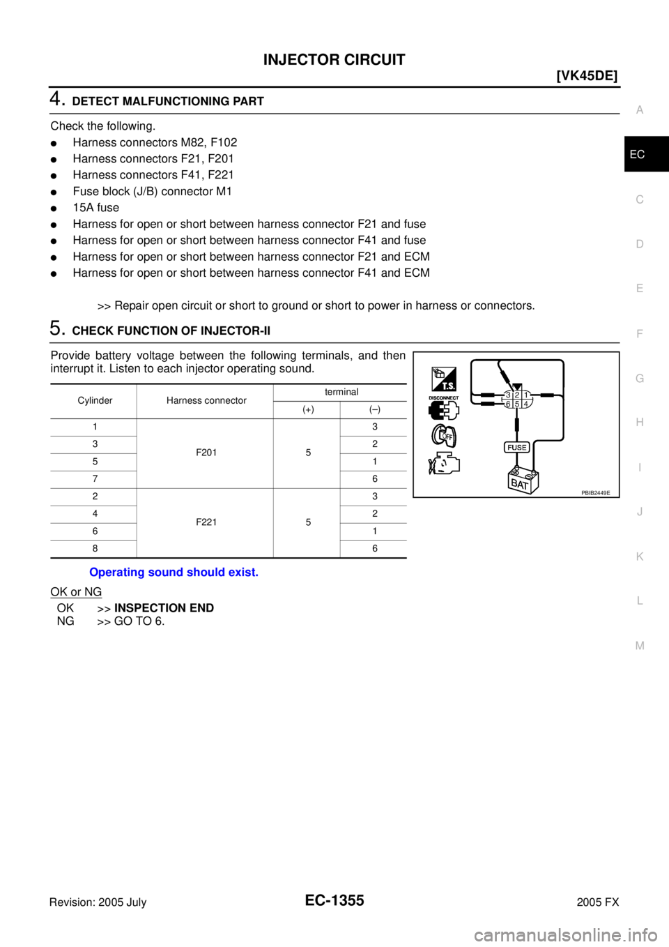
5. CHECK FUNCTION OF INJECTOR-II
Provide battery voltage between the following terminals, and then
interrupt it. Listen to each injector operating sound.
OK or NG
OK >> INSPECTION END
NG >> GO TO 6.
Cylinder Harness connector terminal
(+) (–)
1
F201 5 3
32
51
76
2
F221 5 3
42
61
86
Operating sound should exist.
PBIB2449E