Page 3293 of 4731

GW-16
POWER WINDOW SYSTEM
Revision: 2005 July 2005 FX
System DescriptionAIS004PX
WITH FRONT POWER WINDOW ANTI-PINCH SYSTEM
Power is supplied at all time
�through 50A fusible link (letter M , located in the fuse and fusible link box)
�to BCM terminal 55, and
�through BCM terminal 54
�to power window main switch terminal 19
�to front power window switch (passenger side) terminal 10.
�through 15A fuse [No. 22, located in the fuse block (J/B)]
�to BCM terminal 42.
With ignition switch in ON or START position,
Power is supplied
�through 15A fuse [No. 1 , located in the fuse block (J/B)]
�to BCM terminal 38, and
�trough BCM terminal 53
�to power window main switch terminal 10
�to rear power window switch (LH and RH) terminal 1.
Ground supplied
�to BCM terminal 49 and 52
�through body grounds M35, M45 and M85.
�to power window main switch terminal 17
�through body grounds M35, M45 and M85.
�to front power window switch (passenger side) terminal 11
�through body grounds M35, M45 and M85.
WITH FRONT AND REAR WINDOW ANTI-PINCH SYSTEM
Power is supplied at all time
�through 50A fusible link (letter M , located in the fuse and fusible link box)
�to BCM terminal 55, and
�through BCM terminal 54
�to power window main switch terminal 19
�to front power window switch (passenger side) terminal 10
�to rear power window switch (LH and RH) terminal 10.
�through 15A fuse [No. 22, located in the fuse block (J/B)]
�to BCM terminal 42.
With ignition switch in ON or START position,
Power is supplied
�through 15A fuse [No. 1, located in the fuse block (J/B)]
�to BCM terminal 38, and
�through BCM terminal 53
�to power window main switch terminal 10
Ground supplied
�to BCM terminal 49 and 52
�through body grounds M35, M45 and M85.
�to power window main switch terminal 17
�through body grounds M35, M45 and M85.
�to front power window switch (passenger side) terminal 11
�through body grounds M35, M45 and M85.
�to rear power window switch (LH and RH) terminal 11
�through body grounds B15 and B45.
Page 3305 of 4731
GW-28
POWER WINDOW SYSTEM
Revision: 2005 July 2005 FX
Terminal and Reference Value for BCM / With Front Power Window Anti-Pinch
System
AIS004Q2
Terminal Wire color Item Condition Voltage [V]
(Approx.)
12 P/B Front door switch
passenger side signal ON (Open) 0
OFF (Close) Battery voltage
22 OR Power window serial link IGN SW ON or power window
timer operating.
38 W/L Ignition switch (ON or START) Ignition switch
(ON or START position) Battery voltage
39 L CAN - H — —
40 R CAN - L — —
42 L/R Power source (Fuse) — Battery voltage
49 B Ground (signal) — 0
52 B Ground (power) — 0
53 Y/B Rap signal IGN SW ON Battery voltage
Within 45 second after ignition
switch is turned to OFF Battery voltage
When driver side or passenger
side door is open in power win-
dow timer is operates 0
54 W Power window power supply — Battery voltage
55 G Power source (Fusible link) — Battery voltage
62 W Front door switch
driver side signal ON (Open) 0
OFF (Close) Battery voltage
PIIA2344J
Page 3314 of 4731

POWER WINDOW SYSTEM GW-37
C
D E
F
G H
J
K L
M A
B
GW
Revision: 2005 July 2005 FX
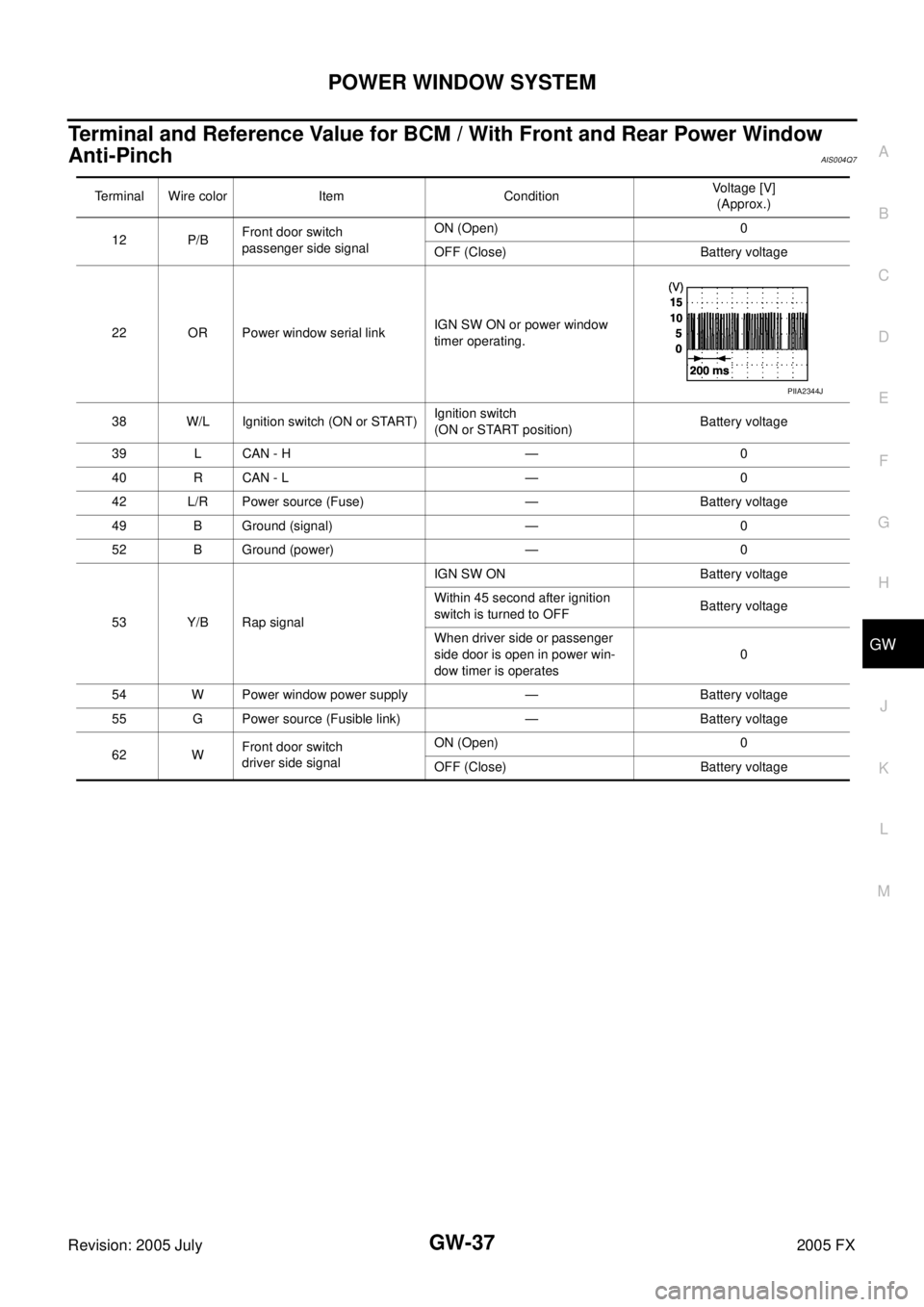
Terminal and Reference Value for BCM / With Front and Rear Power Window
Anti-Pinch
AIS004Q7
Terminal Wire color Item Condition Voltage [V]
(Approx.)
12 P/B Front door switch
passenger side signal ON (Open) 0
OFF (Close) Battery voltage
22 OR Power window serial link IGN SW ON or power window
timer operating.
38 W/L Ignition switch (ON or START) Ignition switch
(ON or START position) Battery voltage
39 L CAN - H — 0
40 R CAN - L — 0
42 L/R Power source (Fuse) — Battery voltage
49 B Ground (signal) — 0
52 B Ground (power) — 0
53 Y/B Rap signal IGN SW ON Battery voltage
Within 45 second after ignition
switch is turned to OFF Battery voltage
When driver side or passenger
side door is open in power win-
dow timer is operates 0
54 W Power window power supply — Battery voltage
55 G Power source (Fusible link) — Battery voltage
62 W Front door switch
driver side signal ON (Open) 0
OFF (Close) Battery voltage
PIIA2344J
Page 3322 of 4731

POWER WINDOW SYSTEM GW-45
C
D E
F
G H
J
K L
M A
B
GW
Revision: 2005 July 2005 FX
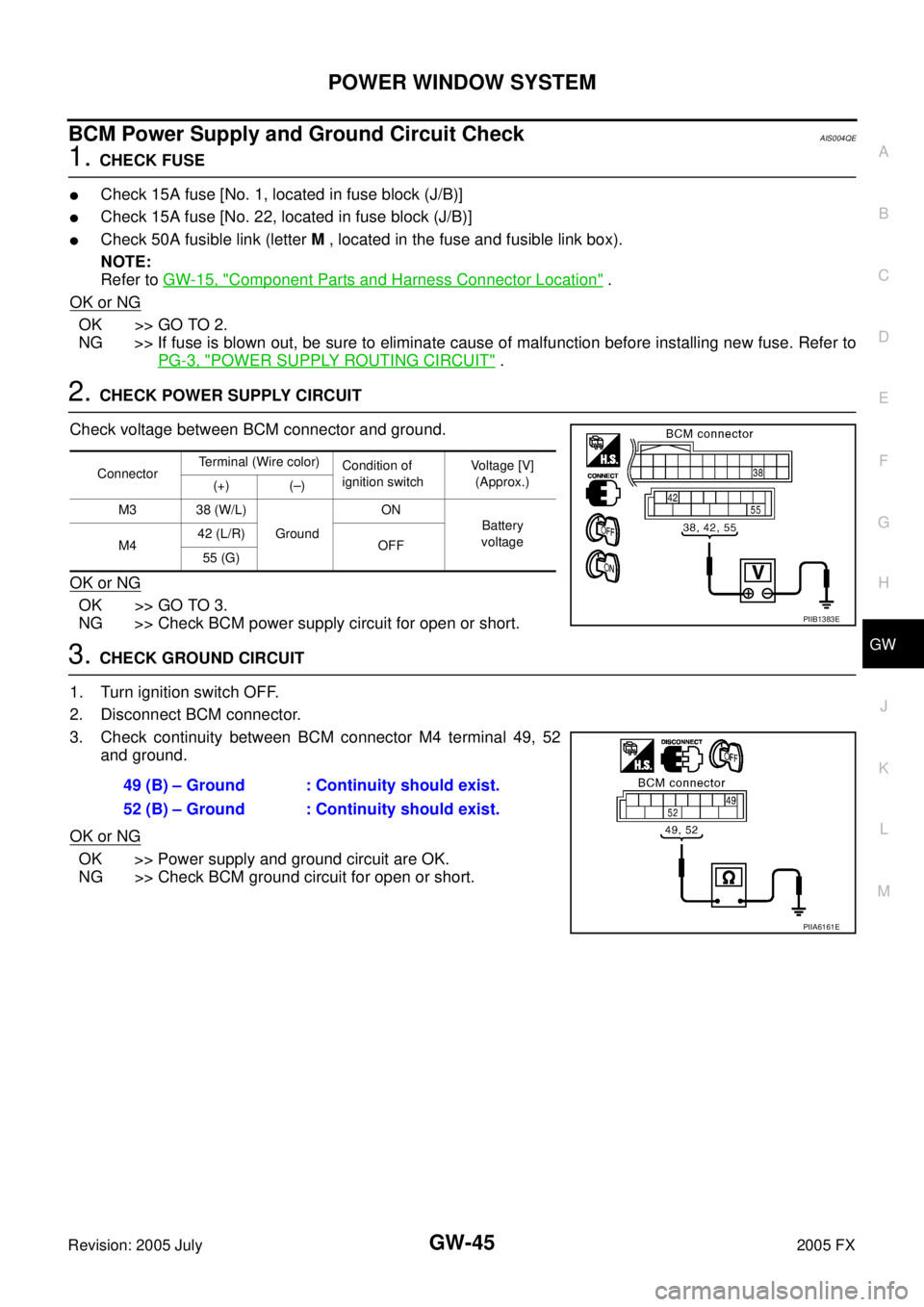
BCM Power Supply and Ground Circuit CheckAIS004QE
1. CHECK FUSE
�Check 15A fuse [No. 1, located in fuse block (J/B)]
�Check 15A fuse [No. 22, located in fuse block (J/B)]
�Check 50A fusible link (letter M , located in the fuse and fusible link box).
NOTE:
Refer to GW-15, "
Component Parts and Harness Connector Location" .
OK or NG
OK >> GO TO 2.
NG >> If fuse is blown out, be sure to eliminate cause of malfunction before installing new fuse. Refer to
PG-3, "
POWER SUPPLY ROUTING CIRCUIT" .
2. CHECK POWER SUPPLY CIRCUIT
Check voltage between BCM connector and ground.
OK or NG
OK >> GO TO 3.
NG >> Check BCM power supply circuit for open or short.
3. CHECK GROUND CIRCUIT
1. Turn ignition switch OFF.
2. Disconnect BCM connector.
3. Check continuity between BCM connector M4 terminal 49, 52 and ground.
OK or NG
OK >> Power supply and ground circuit are OK.
NG >> Check BCM ground circuit for open or short.
Connector Terminal (Wire color)
Condition of
ignition switch Voltage [V]
(Approx.)
(+) (–)
M3 38 (W/L) Ground ON
Battery
voltage
M4 42 (L/R)
OFF
55 (G)
PIIB1383E
49 (B) – Ground : Continuity should exist.
52 (B) – Ground : Continuity should exist.
PIIA6161E
Page 3363 of 4731
GW-86
REAR WINDOW DEFOGGER
Revision: 2005 July 2005 FX
REAR WINDOW DEFOGGERPFP:25350
Component Parts and Harness Connector LocationAIS004QY
System DescriptionAIS004QZ
The rear window defogger system is controlled by BCM (Body Control Module) and IPDM E/R (Intelligent
Power Distribution Module Engine Room).
The rear window defogger operates only for approximately 15 minutes.
Power is at all times supplied
�through 20A fuse [No. 75, located in the IPDM E/R]
�to rear window defogger relay terminals 3,
�through 20A fuse [No. 80, located in the IPDM E/R]
�to rear window defogger relay terminals 6,
�through 10A fuse [No. 12, located in the fuse block]
PIIA6408E
Page 3364 of 4731
![INFINITI FX35 2005 Service Manual REAR WINDOW DEFOGGER GW-87
C
D E
F
G H
J
K L
M A
B
GW
Revision: 2005 July 2005 FX
�to rear window defogger relay terminal 1,
�through 15A fuse [No. 32, located in the fuse block (J/B)]
�t INFINITI FX35 2005 Service Manual REAR WINDOW DEFOGGER GW-87
C
D E
F
G H
J
K L
M A
B
GW
Revision: 2005 July 2005 FX
�to rear window defogger relay terminal 1,
�through 15A fuse [No. 32, located in the fuse block (J/B)]
�t](/manual-img/42/57020/w960_57020-3363.png)
REAR WINDOW DEFOGGER GW-87
C
D E
F
G H
J
K L
M A
B
GW
Revision: 2005 July 2005 FX
�to rear window defogger relay terminal 1,
�through 15A fuse [No. 32, located in the fuse block (J/B)]
�to A/C and AV switch terminal 1,
�through 50A fusible link (letter M , located in the fuse and fusible link box)
�to BCM terminal 55,
�through 15A fuse [No. 22, located in the fuse block (J/B)]
�to BCM terminal 42.
With the ignition switch turned to ON or START position,
Power is supplied
�through 15A fuse [No. 1, located in the fuse block (J/B)]
�to BCM terminal 38.
Ground is supplied
�to BCM terminal 49 and 52
�through body grounds M35, M45 and M85,
�to A/C and AV switch terminal 5
�through body grounds M35, M45 and M85,
�to IPDM E/R terminals 38 and 60
�through body grounds E21, E50 and E51.
When rear window defogger switch in A/C and AV switch is turned to ON,
Ground is supplied
�to BCM terminal 9
�through A/C and AV switch terminal 16
�through A/C and AV switch terminal 5 and
�through body grounds M35, M45 and M85.
Then rear window defogger switch is illuminated.
Then BCM recognizes that rear window defogger switch is turned to ON.
Then it sends rear window defogger switch signals to IPDM E/R, display control unit (with navigation system)
or display unit (without navigation system) via DATA LINE (CAN H, CAN L).
When display control unit (with navigation system) or display unit (without navigation system) receives rear
window defogger switch signals, and display on the screen.
When IPDM E/R receives rear window defogger switch signals,
Ground is supplied
�to rear window defogger relay terminal 2
�through IPDM E/R terminal 52
�through IPDM E/R terminals 38 and 60 and
�through body grounds E21, E50 and E51.
And then rear window defogger relay is energized.
When rear window defogger relay is turned ON, signals are transmitted.
�through rear window defogger relay terminals 5 and 7
�to rear window defogger terminal 1
Rear window defogger terminal 2 is grounded through grounds B15 and B45.
With power and ground supplied, rear window defogger filaments heat and defog the rear window.
When rear window defogger relay is turned to ON,
Power is supplied
�through rear window defogger relay terminal 7
�through fuse block (J/B) terminal 2C
�through 15A fuse [No. 8, located in the fuse block (J/B)] and
�through fuse block (J/B) terminal 5B
�to door mirror defogger (driver side and passenger side) terminal 1.
Door mirror defogger (driver side and passenger side) terminal 2 is grounded through body grounds M35, M45
and M85.
Page 3371 of 4731
GW-94
REAR WINDOW DEFOGGER
Revision: 2005 July 2005 FX
Terminal and Reference Value for BCMAIS004R4
Terminal and Reference Value for IPDM E/RAIS004R5
Terminal Wire color Item Condition Voltage (V)
(Approx.)
9L/W Rear window defogger
switch signal When rear window defogger switch is pressed. 0
When rear window defogger switch is OFF. 5
38 W/L Ignition switch ON or START Ignition switch (ON or START position) Battery voltage
39 L CAN − H——
40 R CAN − L——
42 L/R Power source (Fuse) — Battery voltage
49 B Ground (signal) — 0
52 B Ground (power) — 0
55 G Power source (Fusible link) — Battery voltage
Terminal Wire color Item Condition Voltage (V)
(Approx.)
5 R Battery power supply — Battery voltage
6 W Battery power supply — Battery voltage
38 B Ground (Power) — 0
48 L CAN − H——
49 R CAN − L——
52 G Rear window defogger relay
control signal When rear window defogger switch is ON. 0
When rear window defogger switch is OFF. Battery voltage
60 B Ground (Signal) — 0
Page 3375 of 4731

GW-98
REAR WINDOW DEFOGGER
Revision: 2005 July 2005 FX
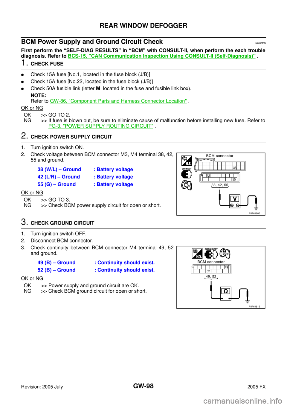
BCM Power Supply and Ground Circuit CheckAIS004R9
First perform the “SELF-DIAG RESULTS” in “BCM” with CONSULT-II, when perform the each trouble
diagnosis. Refer to BCS-15, "
CAN Communication Inspection Using CONSULT-II (Self-Diagnosis)" .
1. CHECK FUSE
�Check 15A fuse [No.1, located in the fuse block (J/B)]
�Check 15A fuse [No.22, located in the fuse block (J/B)]
�Check 50A fusible link (letter M located in the fuse and fusible link box).
NOTE:
Refer to GW-86, "
Component Parts and Harness Connector Location" .
OK or NG
OK >> GO TO 2.
NG >> If fuse is blown out, be sure to eliminate cause of malfunction before installing new fuse. Refer to PG-3, "
POWER SUPPLY ROUTING CIRCUIT" .
2. CHECK POWER SUPPLY CIRCUIT
1. Turn ignition switch ON.
2. Check voltage between BCM connector M3, M4 terminal 38, 42, 55 and ground.
OK or NG
OK >> GO TO 3.
NG >> Check BCM power supply circuit for open or short.
3. CHECK GROUND CIRCUIT
1. Turn ignition switch OFF.
2. Disconnect BCM connector.
3. Check continuity between BCM connector M4 terminal 49, 52 and ground.
OK or NG
OK >> Power supply and ground circuit are OK.
NG >> Check BCM ground circuit for open or short. 38 (W/L) – Ground : Battery voltage
42 (L/R) – Ground : Battery voltage
55 (G) – Ground : Battery voltage
PIIA6160E
49 (B) – Ground : Continuity should exist.
52 (B) – Ground : Continuity should exist.
PIIA6161E