Page 391 of 4731
AT-308
REPAIR FOR COMPONENT PARTS
Revision: 2005 July 2005 FX
REPAIR FOR COMPONENT PARTSPFP:00000
Oil PumpACS0081M
COMPONENTS
DISASSEMBLY
1. Remove oil pump housing from oil pump cover.
2. Remove oil pump housing oil seal using a flat-bladed screw- driver.
CAUTION:
Be careful not to scratch oil pump housing.
1. O-ring 2. Oil pump cover 3. O-ring
4. Oil pump housing 5. Oil pump housing oil seal
SCIA5323E
SCIA6388E
SCIA2840E
Page 392 of 4731
REPAIR FOR COMPONENT PARTS AT-309
D E
F
G H
I
J
K L
M A
B
AT
Revision: 2005 July 2005 FX
3. Remove O-ring from oil pump housing.
4. Remove O-ring from oil pump cover.
ASSEMBLY
1. Install O-ring to oil pump cover.
CAUTION:
�Do not reuse O-ring.
�Apply ATF to O-ring.
2. Install O-ring to oil pump housing. CAUTION:
�Do not reuse O-ring.
�Apply ATF to O-ring.
SCIA2841E
SCIA5230E
SCIA5230E
SCIA2841E
Page 393 of 4731
AT-310
REPAIR FOR COMPONENT PARTS
Revision: 2005 July 2005 FX
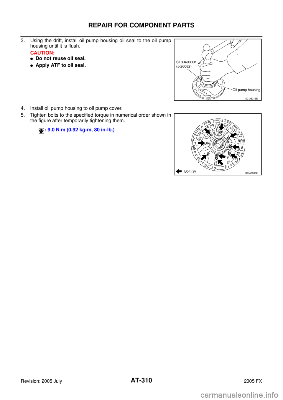
3. Using the drift, install oil pump housing oil seal to the oil pump
housing until it is flush.
CAUTION:
�Do not reuse oil seal.
�Apply ATF to oil seal.
4. Install oil pump housing to oil pump cover.
5. Tighten bolts to the specified torque in numerical order shown in the figure after temporarily tightening them.
SCIA5313E
: 9.0 N·m (0.92 kg-m, 80 in-lb.)
SCIA6388E
Page 395 of 4731
AT-312
REPAIR FOR COMPONENT PARTS
Revision: 2005 July 2005 FX
INSPECTION
3rd One-way Clutch
�Check frictional surface for wear or damage.
CAUTION:
If necessary, replace the 3rd one-way clutch.
Front Sun Gear Snap Ring
�Check for deformation, fatigue or damage.
CAUTION:
If necessary, replace the snap ring.
Front Sun Gear
�Check for deformation, fatigue or damage.
CAUTION:
If necessary, replace the front sun gear.
ASSEMBLY
1. Install 3rd one-way clutch in front sun gear.
CAUTION:
Apply ATF to 3rd one-way clutch.
2. Using a flat-bladed screwdriver, install snap ring in front sun gear.
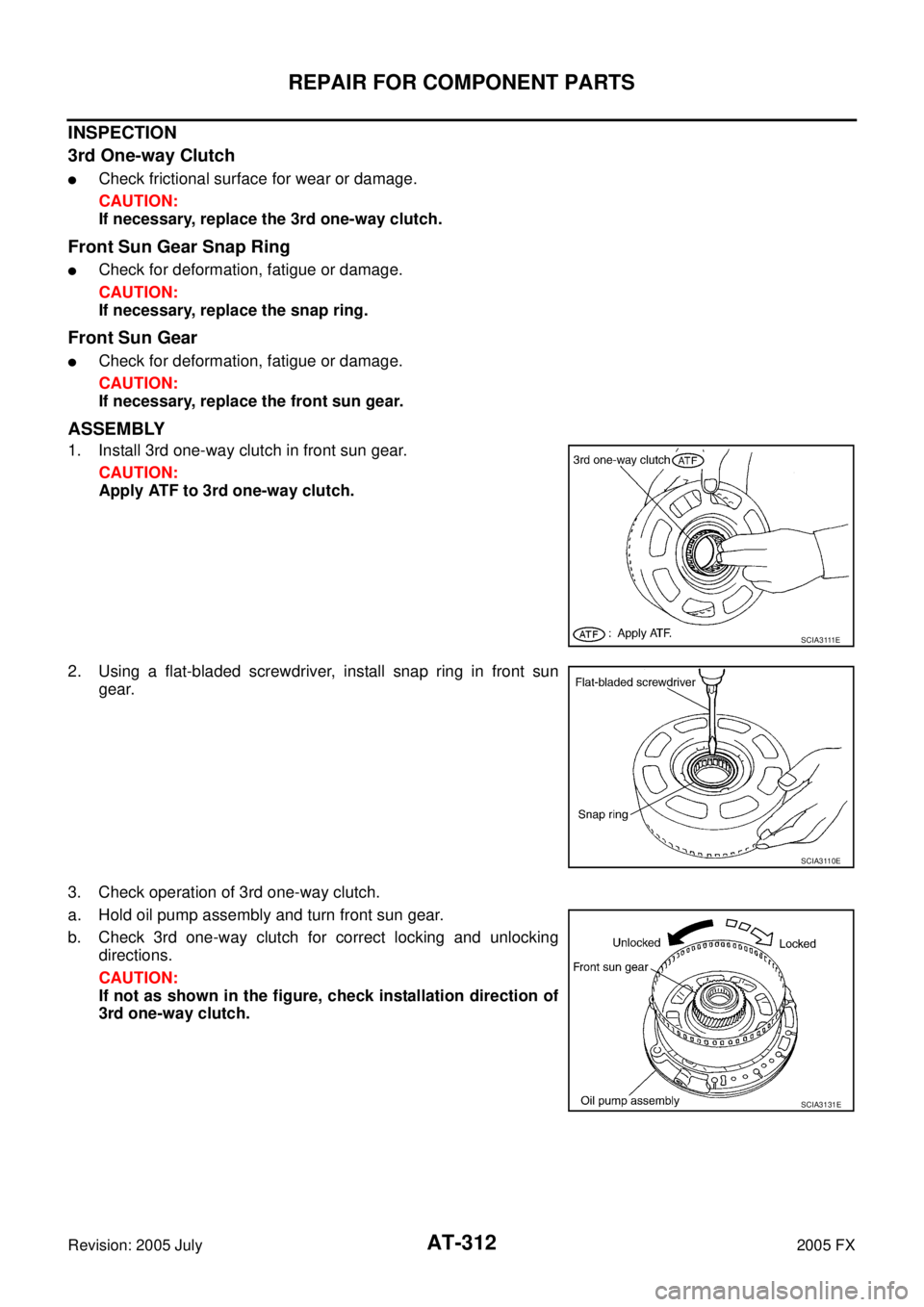
3. Check operation of 3rd one-way clutch.
a. Hold oil pump assembly and turn front sun gear.
b. Check 3rd one-way clutch for correct locking and unlocking directions.
CAUTION:
If not as shown in the figure, check installation direction of
3rd one-way clutch.
S C I A 3 111 E
SCIA3110E
SCIA3131E
Page 411 of 4731
AT-328
ASSEMBLY
Revision: 2005 July 2005 FX
ASSEMBLYPFP:00000
Assembly (1)ACS0081S
1. As shown in the figure, use a drift [commercial service tool:
22mm (0.87in)dia.] to drive manual shaft oil seals into the trans-
mission case until it is flush.
CAUTION:
�Apply ATF to manual shaft oil seals.
�Do not reuse manual shaft oil seals.
2. Install detent spring and spacer in transmission case.
3. Install manual shaft to transmission case.
4. Install parking rod to manual plate.
SCIA5259E
: 7.9 N·m (0.81 kg-m, 70 in-lb)
SCIA5248E
SCIA5716E
SCIA5220E
Page 416 of 4731
ASSEMBLY AT-333
D E
F
G H
I
J
K L
M A
B
AT
Revision: 2005 July 2005 FX
22. Measure clearance between retaining plate and snap ring. If not
within specified clearance, select proper retaining plate.
23. Install needle bearing to transmission case. CAUTION:
Apply petroleum jelly to needle bearing.
24. Install revolution sensor to transmission case. CAUTION:
�Do not subject it to impact by dropping or hitting it.
�Do not disassemble.
�Do not allow metal filings, etc., to get on the sensor's
front edge magnetic area.
�Do not place in an area affected by magnetism.
25. As shown in the figure, use the drift to drive rear oil seal into the rear extension (2WD models) or adapter case (AWD models)
until it is flush.
CAUTION:
�Apply ATF to rear oil seal.
�Do not reuse rear oil seal. Specified clearance “A”:
Standard: 0.7 - 1.1mm (0.028 - 0.043 in)
Retaining plate: Refer to AT- 3 5 3 , "
Reverse Brake" .
SCIA3129E
SCIA5031E
: 5.8 N·m (0.59 kg-m, 51 in-lb)
SCIA2320E
SCIA5477E
Page 418 of 4731
ASSEMBLY AT-335
D E
F
G H
I
J
K L
M A
B
AT
Revision: 2005 July 2005 FX
31. Install parking gear to output shaft.
32. Install output shaft in transmission case. CAUTION:
Be careful not to mistake front for rear because both sides
looks similar. (Thinner end is front side.)
33. Install bearing race to output shaft.
34. Install rear extension assembly (2WD models) or adapter case assembly (AWD models) according to the following procedures.
a. 2WD models
i. Apply recommended sealant (Genuine Anaerobic Liquid Gasket or equivalent. Refer to GI-48, "
Recommended Chemical Prod-
ucts and Sealants" .) to rear extension assembly as shown in
the figure.
CAUTION:
Completely remove all moisture, oil and old sealant, etc.
from the transmission case and rear extension assembly
mounting surfaces.
SCIA5247E
SCIA5030E
SCIA5245E
SCIA5212E
Page 419 of 4731
AT-336
ASSEMBLY
Revision: 2005 July 2005 FX
ii. Install rear extension assembly to transmission case.
CAUTION:
Insert the tip of parking rod between the parking pawl and
the parking actuator support when assembling the rear
extension assembly.
iii. Tighten rear extension assembly mounting bolts to specified torque.
CAUTION:
Do not reuse self-sealing bolt.
b. AW D m o d e l s
i. Install gasket onto transmission case. CAUTION:
�Completely remove all moisture, oil and old gasket, etc.
from the transmission case and adapter case assembly
mounting surfaces.
�Do not reuse gasket.
ii. Install adapter case assembly to transmission case. CAUTION:
Insert the tip of parking rod between the parking pawl and
the parking actuator support when assembling the rear
extension assembly.
SCIA5029E
Rear extension assembly mounting bolt:
: 52 N·m (5.3 kg-m, 38 ft-lb)
Self-sealing bolt: : 61 N·m (6.2 kg-m, 45 ft-lb)
SCIA6941E
SCIA5231E
SCIA5186E


![INFINITI FX35 2005 Service Manual AT-328
ASSEMBLY
Revision: 2005 July 2005 FX
ASSEMBLYPFP:00000
Assembly (1)ACS0081S
1. As shown in the figure, use a drift [commercial service tool:
22mm (0.87in)dia.] to drive manual shaft oil seals](/manual-img/42/57020/w960_57020-410.png "INFINITI FX35 2005 Service Manual AT-328
ASSEMBLY
Revision: 2005 July 2005 FX
ASSEMBLYPFP:00000
Assembly (1)ACS0081S
1. As shown in the figure, use a drift [commercial service tool:
22mm (0.87in)dia.] to drive manual shaft oil seals")


