2004 SUBARU FORESTER rear turn signal
[x] Cancel search: rear turn signalPage 66 of 2870

AC-10
HVAC SYSTEM (AUTO A/C)(DIAGNOSTIC)
Diagnostic Chart for Self-Diagnosis
Step Check Yes No
1 SELECT CONTROL PANEL TO SELF-DIAG-
NOSIS MODE.
1) Turn the ignition switch to OFF.
2) Start the engine while pressing defroster
switch and A/C switch.
N
OTE:
Self-diagnosis can also be performed with the
ignition switch ON, but start the engine be-
cause telling the magnet clutch operation is dif-
ficult.
3) The LED in A/C control panel blinks.Does the self-diagnosis mode
operate?Go to step 2.
NOSIS SYS-
TEMS DO NOT
OPERATE, Diag-
nostics for A/C
System Malfunc-
tion.>
2 CHECK LED ILLUMINATION.
Make sure that three LED blink in turn on A/C
control panel (5 patterns are repeated 2 times).Do all LED blink? Go to step 3.Go to step 5.
3 CHECK SENSORS MALFUNCTION.
1) After completing the LED check or when
AUTO switch is pressed, the A/C switch LED
illuminates, and then the sensor check is
started.
2) Check the input signal of each sensor in
turn. If there are any trouble for each sensor,
DEF, MODE and fan speed LEDs are blinked.
Also check for each sensor is possible respec-
tively every time AUTO switch is pressed. (At
this time, the AUTO switch LED illuminates.)
3) If there is no trouble, DEF, MODE and fan
speed LEDs are turned off.
N
OTE:
Rear window defogger LED illuminates in case
of stored malfunction but does not illuminate in
case of present malfunction.Does each DEF, MODE and
fan speed LED turn off?Go to step 4.Confirm the com-
bination of illumi-
nating LEDs by
using Sensor
Check Table, and
identify the mal-
functioning sensor
before repairing.
TABLE, OPERA-
TION, Diagnostic
Chart for Self-
Diagnosis.>
4 CHECK OPERATION OF EACH ACTUATOR,
COMPRESSOR AND FAN MOTOR.
1) Press the FRESH/RECIRC switch
(FRESH/RECIRC switch LED illuminates at
this time.).
2) Refer to OPERATING MODE TABLE to
check the operation of each actuator, compres-
sor and fan motor.
Chart for Self-Diagnosis.>
Also check for each step is possible respec-
tively every time AUTO switch pressed. (At this
time, the AUTO switch LED illuminates.)Does each actuator, compres-
sor and fan motor operate
according to operating mode
table?Press the OFF
switch or turn the
ignition switch to
OFF and finish the
self-diagnosis
mode.Refer to each
diagnostics chart
for actuator, com-
pressor and fan
motor, and repair
the malfunctioning
par t as necessary.
C System Mal-
function.>
Procedure for
Actuators.>
5 CHECK POOR CONTACT.
Check the auto A/C control module connector
for poor contact.Is there a poor contact in con-
nector?Replace the auto
A/C control mod-
ule.Repair the con-
nector.
Page 243 of 2870

SB-9
SEAT BELT SYSTEM
Seat Belt Warning System
14 CHECK HARNESS BETWEEN TCU AND
SEAT BELT TIMER MODULE.
Measure the resistance between seat belt
timer module harness connector and chassis
ground.
Connector & terminal
(B44) No. 7 — Chassis ground:Is the resistance less than 10
Ω?Go to step 15.Repair the short of
harness.
15 CHECK SEAT BELT TIMER MODULE OUT-
PUT SIGNAL.
1) Turn the ignition switch to ON.
2) Measure the voltage between seat belt
timer module harness connector and chassis
ground.
Connector & terminal
(B44) No. 2 (+) — Chassis ground (–):Is the voltage more than 10 V? Go to step 16.Check the wiring
harness and com-
bination meter,
and then repair or
replace them.
16 CHECK POOR CONTACT.
Check the poor contact of seat belt warning
light circuit.Is there any poor contact
occurs?Repair the poor
contact.Go to step 17.
17 CHECK SEAT BELT TIMER MODULE.
1) Connect all connectors.
2) Lift-up the vehicle and place rigid racks.
NOTE:
Raise all wheels off floor.
3) Hold the tang plate disconnected from seat
belt buckle.
4) Start the engine, and set the vehicle speed
less than 19 km/h (12 MPH)
N
OTE:
The speed difference between front and rear
wheels may light the ABS warning light, but this
indicates no malfunction. When diagnosis is fin-
ished, perform the ABS memory clearance pro-
cedure of OBD system.
Check seat belt warning light comes on.Does the seat belt warning
light come on?Go to step 18.Replace the seat
belt timer module.
18 CHECK SEAT BELT TIMER MODULE.
1) Connect all connectors.
2) Lift-up the vehicle and place rigid racks.
N
OTE:
Raise all wheels off floor.
3) Hold the tang plate disconnected from seat
belt buckle.
4) Start the engine, and set the vehicle speed
more than 25 km/h (16 MPH).
NOTE:
The speed difference between front and rear
wheels may light the ABS warning light, but this
indicates no malfunction. When diagnosis is fin-
ished, perform the ABS memory clearance pro-
cedure of OBD system.
Check seat belt warning light comes on and
buzzer beeps.Does the seat belt warning
light come on and buzzer
beep?Temporary poor
contact of connec-
tor or harness may
be the cause.
Check the poor
contact.Replace the seat
belt timer module. Step Check Yes No
Page 255 of 2870

LIGHTING SYSTEM
LI
Page
1. General Description ....................................................................................2
2. Headlight and Tail Light System .................................................................3
3. Front Fog Light System ...............................................................................4
4. Rear Fog Light System ...............................................................................5
5. Turn Signal Light and Hazard Light System................................................6
6. Back-up Light System .................................................................................7
7. Stop Light System .......................................................................................8
8. Room Light System .....................................................................................9
9. Headlight Beam Leveler System ...............................................................10
10. Combination Switch (Light) .......................................................................11
11. Headlight Assembly ..................................................................................13
12. Headlight Bulb ...........................................................................................16
13. Front Turn Signal Light Bulb .....................................................................17
14. Clearance Light Bulb .................................................................................18
15. Front Fog Light Assembly .........................................................................19
16. Front Fog Light Bulb..................................................................................20
17. Rear Combination Light Assembly ............................................................21
18. Tail/Stop Light Bulb ...................................................................................22
19. Back-up Light Bulb ....................................................................................23
20. Rear Turn Signal Light Bulb ......................................................................24
21. Rear Fog Light Bulb ..................................................................................25
22. License Plate Light ....................................................................................26
23. High-mounted Stop Light ..........................................................................27
24. Side Turn Signal Light ...............................................................................28
25. Spot Map Light ..........................................................................................29
26. Room Light ................................................................................................30
27. Luggage Room Light .................................................................................31
28. Glove Box Light .........................................................................................32
Page 256 of 2870

LI-2
LIGHTING SYSTEM
General Description
1. General Description
A: SPECIFICATION
B: PRECAUTIONS
Before removing and installing parts, always disconnect the battery ground cable. When replacing audio,
control module, and other parts provided with memory functions, record memory contents before disconnect-
ing the battery ground cable. Otherwise, the memory will be erased.
Reassemble in reverse order of disassembly, unless otherwise indicated.
Adjust parts to the given specifications.
Connect the connectors and hoses securely during reassembly.
After reassembly, make sure functional parts operate smoothly.
WARNING:
Airbag system wiring harness is routed near electrical parts and switches. All airbag system wiring
harnesses and connectors are yellow. Do not use electric test equipment on these circuits.
Be careful not to damage the airbag system wiring harness when servicing electrical parts and
switches.
C: PREPARATION TOOL
1. GENERAL TOOL
Headlight12 V — 55 W/60 W
Front turn signal light 12 V — 21 W
Clearance light12 V — 5 W
Side marker light12 V — 5 W
Front fog light12 V — 55 W
Rear combination lightTail/Stop light 12 V — 5/21 W
Turn signal light 12 V — 21 W
Back-up light 12 V — 16 W
License plate light12 V — 5 W
High-mounted stop lightStandard type 12 V — 13 W
Rear spoiler built-in type 12 V — 1.2 W
Room light12 V — 8 W
Spot light12 V — 8 W
Luggage room light12 V — 5 W
TOOL NAME REMARKS
Circuit tester Used for measuring resistance and voltage.
Page 265 of 2870
LI-11
LIGHTING SYSTEM
Combination Switch (Light)
10.Combination Switch (Light)
A: REMOVAL
1) Disconnect the ground cable from battery.
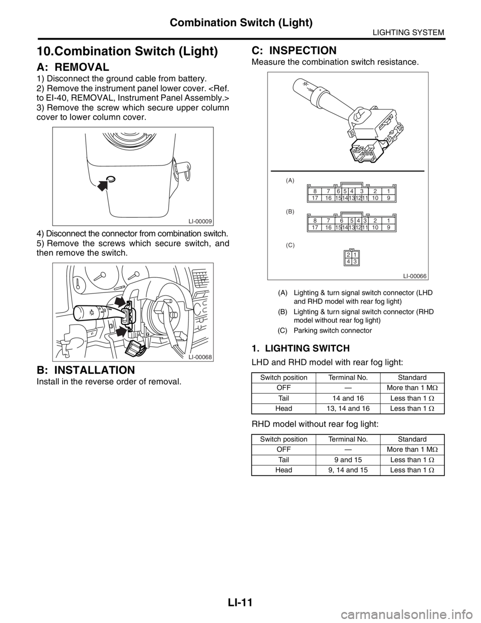
2) Remove the instrument panel lower cover.
3) Remove the screw which secure upper column
cover to lower column cover.
4) Disconnect the connector from combination switch.
5) Remove the screws which secure switch, and
then remove the switch.
B: INSTALLATION
Install in the reverse order of removal.
C: INSPECTION
Measure the combination switch resistance.
1. LIGHTING SWITCH
LHD and RHD model with rear fog light:
RHD model without rear fog light:
LI-00009
LI-00068
(A) Lighting & turn signal switch connector (LHD
and RHD model with rear fog light)
(B) Lighting & turn signal switch connector (RHD
model without rear fog light)
(C) Parking switch connector
Switch position Terminal No. Standard
OFF — More than 1 MΩ
Tail 14 and 16 Less than 1 Ω
Head 13, 14 and 16 Less than 1 Ω
Switch position Terminal No. Standard
OFF — More than 1 MΩ
Tail 9 and 15 Less than 1 Ω
Head 9, 14 and 15 Less than 1 Ω
LI-00066
1514131211109171665432187
1514
2143
131211109171665432187
(A)
(B)
(C)
Page 266 of 2870

LI-12
LIGHTING SYSTEM
Combination Switch (Light)
2. DIMMER AND PASSING SWITCH
LHD and RHD model with rear fog light:
RHD model without rear fog light:
3. TURN SIGNAL SWITCH
LHD and RHD with rear fog light:
RHD model without rear fog light:
4. PARKING SWITCH
Switch position Terminal No. Standard
Passing 7, 8 and 16 Less than 1 Ω
Low beam 16 and 17 Less than 1 Ω
High beam 7 and 16 Less than 1 Ω
Switch position Terminal No. Standard
Passing 1, 2 and 9 Less than 1 Ω
Low beam 9 and 10 Less than 1 Ω
High beam 2 and 9 Less than 1 Ω
Switch position Terminal No. Standard
Left 1 and 2 Less than 1 Ω
Neutral — More than 1 MΩ
Right 2 and 3 Less than 1 Ω
Switch position Terminal No. Standard
Left 6 and 7 Less than 1 Ω
Neutral — More than 1 MΩ
Right 7 and 8 Less than 1 Ω
Switch position Terminal No. Standard
OFF 2 and 4 Less than 1 Ω
ON 1 and 4 Less than 1 Ω
Page 278 of 2870
LI-24
LIGHTING SYSTEM
Rear Turn Signal Light Bulb
20.Rear Turn Signal Light Bulb
A: REMOVAL
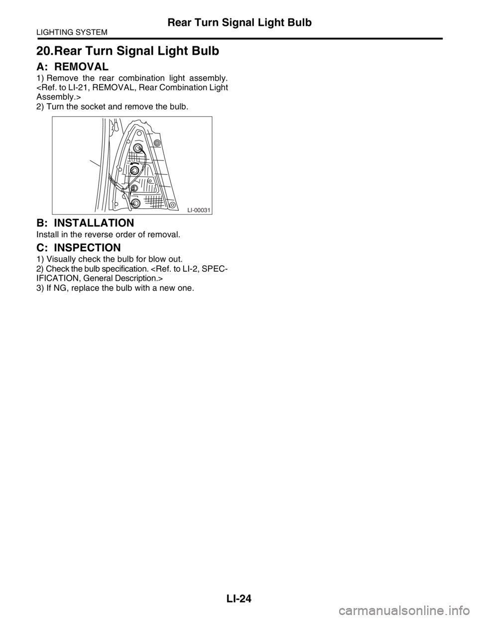
1) Remove the rear combination light assembly.
2) Turn the socket and remove the bulb.
B: INSTALLATION
Install in the reverse order of removal.
C: INSPECTION
1) Visually check the bulb for blow out.
2) Check the bulb specification.
3) If NG, replace the bulb with a new one.
LI-00031
Page 386 of 2870

IDI-2
INSTRUMENTATION/DRIVER INFO
General Description
1. General Description
A: SPECIFICATION
B: CAUTION
Be careful not to damage meters and instrument panel.
Be careful not to damage meter glasses.
Make sure that electrical connector is connected securely.
After installation, make sure that each meter operates normally.
Use gloves to avoid damage and getting fingerprints on the glass surface and meter surfaces.
Do not apply excessive force to the printed circuit.
Do not drop or otherwise apply impact.
C: PREPARATION TOOL
1. GENERAL TOOL
Combination meterSpeedometer Electric pulse type
Temperature gauge Cross coil type
Fuel gauge Cross coil type
Tachometer Electric pulse type
Turn signal indicator light 14 V — 2 W
Charge indicator light 14 V — 1.4 W
Oil pressure indicator light LED
ABS warning light 14 V — 1.4 W
Malfunction indicator light LED
HI-beam indicator light 14 V — 2 W
Door open warning light LED
Seat belt warning light LED
Brake fluid and parking brake warning
light14 V — 2 W
FWD indicator light LED
AIRBAG warning light LED
Meter illumination light 14 V — 3.4 W, 14 V — 2 W
AT OIL TEMP. warning light LED
LO indicator light LED
HOLD indicator light LED
Immobilizer indicator light LED
Rear differential oil temperature warn-
ing light14 V — 2 W
Cruise indicator light 14 V — 1.4 W
Rear fog light indicator light 14 V — 2 W
POWER indicator light 14 V — 1.4 W
Low fuel warning light LED
AT select lever position indicator light 14 V — 100 mA
LCD back light 14 V — 1.4 W
TOOL NAME REMARKS
Circuit tester Used for measuring resistance and voltage.