2004 SUBARU FORESTER sensor
[x] Cancel search: sensorPage 1984 of 2870
FU(H4DOTC 2.5)-54
FUEL INJECTION (FUEL SYSTEM)
Fuel Level Sensor
25.Fuel Level Sensor
A: REMOVAL
WARNING:
Place “NO FIRE” signs near the working area.
Be careful not to spill fuel on the floor.
NOTE:
Fuel level sensor is built in fuel pump assembly.
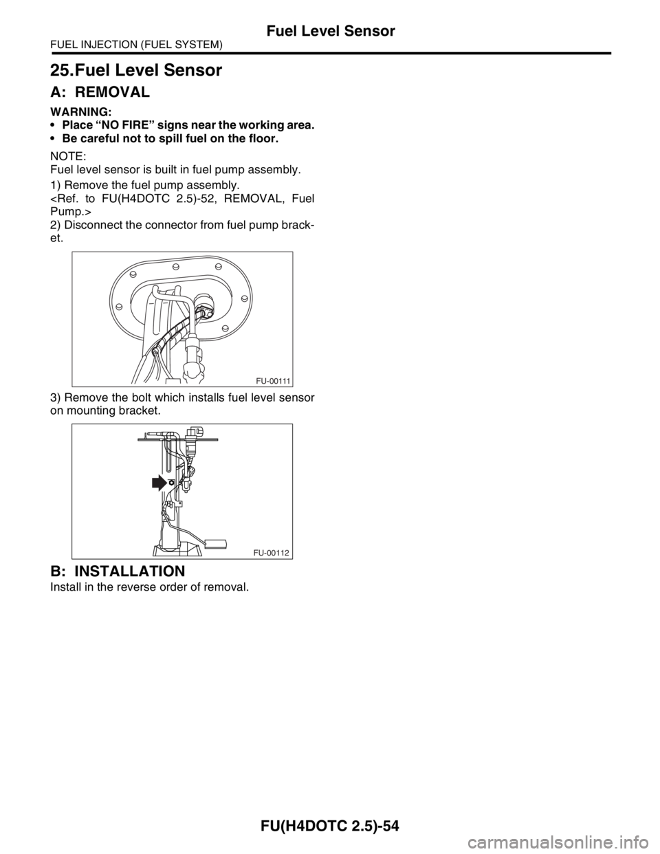
1) Remove the fuel pump assembly.
2) Disconnect the connector from fuel pump brack-
et.
3) Remove the bolt which installs fuel level sensor
on mounting bracket.
B: INSTALLATION
Install in the reverse order of removal.
FU-00111
FU-00112
Page 1985 of 2870
FU(H4DOTC 2.5)-55
FUEL INJECTION (FUEL SYSTEM)
Fuel Sub Level Sensor
26.Fuel Sub Level Sensor
A: REMOVAL
WARNING:
Place “NO FIRE” signs near the working area.
Be careful not to spill fuel on the floor.
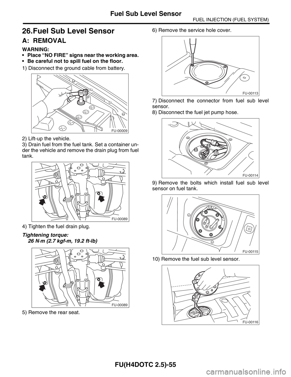
1) Disconnect the ground cable from battery.
2) Lift-up the vehicle.
3) Drain fuel from the fuel tank. Set a container un-
der the vehicle and remove the drain plug from fuel
tank.
4) Tighten the fuel drain plug.
Tightening torque:
26 N
⋅m (2.7 kgf-m, 19.2 ft-lb)
5) Remove the rear seat.6) Remove the service hole cover.
7) Disconnect the connector from fuel sub level
sensor.
8) Disconnect the fuel jet pump hose.
9) Remove the bolts which install fuel sub level
sensor on fuel tank.
10) Remove the fuel sub level sensor.
FU-00009
FU-00089
FU-00089
FU-00113
FU-00114
FU-00115
FU-00116
Page 1986 of 2870
FU(H4DOTC 2.5)-56
FUEL INJECTION (FUEL SYSTEM)
Fuel Sub Level Sensor
B: INSTALLATION
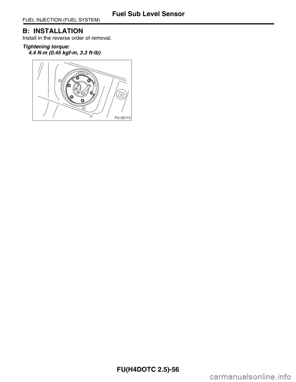
Install in the reverse order of removal.
Tightening torque:
4.4 N·m (0.45 kgf-m, 3.3 ft-lb)
FU-00115
Page 1993 of 2870

FU(H4DOTC 2.5)-63
FUEL INJECTION (FUEL SYSTEM)
Fuel System Trouble in General
31.Fuel System Trouble in General
A: INSPECTION
NOTE:
When the vehicle is left unattended for an extended period of time, water may accumulate in the fuel tank.
To prevent water condensation.
(1) Top off the fuel tank or drain the fuel completely.
(2) Drain the water condensation from the fuel filter.
Refilling the fuel tank.
Refill the fuel tank while there is still some fuel left in the tank.
Protecting the fuel system against freezing and water condensation.
(3) Cold areas:
In snow-covered areas, mountainous areas, skiing areas, etc. where ambient temperatures drop below
0°C (32°F) throughout the winter season, use an anti-freeze solution in the cooling system. Refueling will
also complement the effect of anti-freeze solution each time the fuel level drops to about one-half. After
the winter season, drain the water which may have accumulated in the fuel filter and fuel tank in the man-
ner same as that described under “Affected areas” below.
(4) Affected areas:
When the water condensation is notched in the fuel filter, drain the water from both the fuel filter and fuel
tank or use a water removing agent (or anti-freeze solution) in the fuel tank.
Observe the instructions, notes, etc., indicated on the label affixed to the anti-freeze solution (water remov-
ing agent) container before use.
Trouble and possible cause Corrective action
1. Insufficient fuel supply to the injector
1) Fuel pump will not operate.
❍Defective terminal contact.Inspect connections, especially ground, and tighten
securely.
❍Trouble in electromagnetic or electronic circuit parts. Replace the fuel pump.
2) Lowering of fuel pump function. Replace the fuel pump.
3) Clogged dust or water in the fuel filter. Replace the fuel filter, clean or replace fuel tank.
4) Clogged or bent fuel pipe or hose. Clean, correct or replace the fuel pipe or hose.
5) Air is mixed in the fuel system. Inspect or retighten each connection part.
6) Clogged or bent breather tube or pipe. Clean, correct or replace the air breather tube or pipe.
7) Damaged diaphragm of pressure regulator. Replace.
2. Leakage or blow out fuel
1) Loosened joints of the fuel pipe. Retightening.
2) Cracked fuel pipe, hose and fuel tank. Replace.
3) Defective welding part on the fuel tank. Replace.
4) Defective drain packing of the fuel tank. Replace.
5) Clogged or bent air breather tube or air vent tube.Clean, correct or replace the air breather tube or air vent
tube.
3. Gasoline smell inside of compartment
1)Loose joints at air breather tube, air vent tube and fuel filler
pipe.Retightening.
2) Defective packing air tightness on the fuel saucer. Correct or replace the packing.
3) Cracked fuel separator. Replace the separator.
4) Inoperative fuel pump modulator or circuit. Replace.
4. Defective fuel meter indicator
1) Defective operation of fuel level sensor. Replace.
2) Defective operation of fuel meter. Replace.
5. Noise
1) Large operation noise or vibration of fuel pump. Replace.
Page 2016 of 2870

SP(H4DOTC 2.5)-3
SPEED CONTROL SYSTEM
General Description
C: CAUTION
Wear work clothing, including a cap, protective
goggles, and protective shoes during operation.
Remove contamination, including dirt and corro-
sion, before removal, installation or disassembly.
Keep the disassembled parts in order and pro-
tect them from dust and dirt.
Before removal, installation or disassembly, be
sure to clarify the failure. Avoid unnecessary re-
moval, installation, disassembly, and replacement.
Be careful not to burn your hands, because each
part in the vehicle is hot after running.
Be sure to tighten fasteners including bolts and
nuts to the specified torque.
Place shop jacks or rigid racks at the specified
points.
Before disconnecting electrical connectors of
sensors or units, be sure to disconnect the ground
cable from battery.
Page 2029 of 2870
EN(H4DOTC 2.5)-5
ENGINE (DIAGNOSTIC)
General Description
3. General Description
A: CAUTION
1) Airbag system wiring harness is routed near the
ECM, main relay and fuel pump relay.
CAUTION:
All airbag system wiring harness and con-
nectors are all colored yellow. Do not use the
electrical test equipment on these circuits.
Be careful not to damage the Airbag system
wiring harness when servicing the ECM, TCM,
main relay and fuel pump relay.
2) Never connect the battery in reverse polarity.
The ECM will be destroyed immediately.
The fuel injector and other part will be damaged.
3) Do not disconnect the battery terminals while the
engine is running.
A large counter electromotive force will be gener-
ated in the generator, and this voltage may damage
electronic parts such as ECM, etc.
4) Before disconnecting the connectors of each
sensor and the ECM, be sure to turn OFF the igni-
tion switch.
5) Poor contact has been identified as a primary
cause of this problem. Measure the voltage or re-
sistance of individual sensor or all electrical control
modules using a tapered pin with a diameter of less
than 0.64 mm (0.025 in). Do not insert the pin more
than 5 mm (0.20 in) into the part.
6) Remove the ECM from the located position after
disconnecting two cables on battery.
Otherwise, the ECM may be damaged.
CAUTION:
When replacing the ECM, be careful not to use
the wrong spec. ECM to avoid damaging the
fuel injection system.
7) Connectors to each sensor in the engine com-
partment and the harness connectors on the en-
gine side and body side are all designed to be
waterproof. However, take care not to allow water
to get into the connectors when washing the vehi-
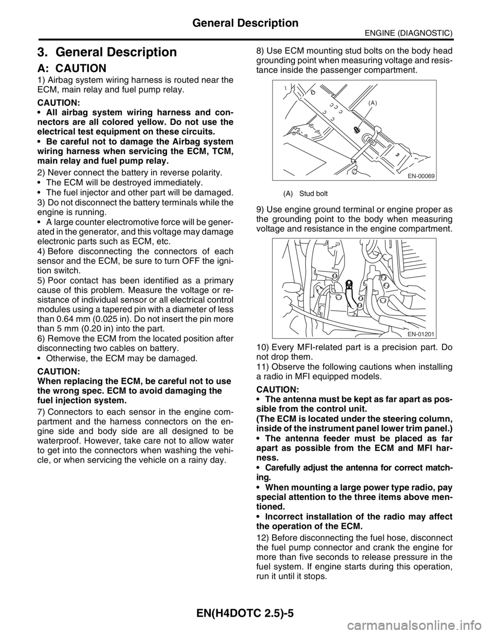
cle, or when servicing the vehicle on a rainy day. 8) Use ECM mounting stud bolts on the body head
grounding point when measuring voltage and resis-
tance inside the passenger compartment.
9) Use engine ground terminal or engine proper as
the grounding point to the body when measuring
voltage and resistance in the engine compartment.
10) Every MFI-related part is a precision part. Do
not drop them.
11) Observe the following cautions when installing
a radio in MFI equipped models.
CAUTION:
The antenna must be kept as far apart as pos-
sible from the control unit.
(The ECM is located under the steering column,
inside of the instrument panel lower trim panel.)
The antenna feeder must be placed as far
apart as possible from the ECM and MFI har-
ness.
Carefully adjust the antenna for correct match-
ing.
When mounting a large power type radio, pay
special attention to the three items above men-
tioned.
Incorrect installation of the radio may affect
the operation of the ECM.
12) Before disconnecting the fuel hose, disconnect
the fuel pump connector and crank the engine for
more than five seconds to release pressure in the
fuel system. If engine starts during this operation,
run it until it stops.
(A) Stud bolt
EN-00069
(A)
EN-01201
Page 2030 of 2870
EN(H4DOTC 2.5)-6
ENGINE (DIAGNOSTIC)
General Description
13) Diagnostics should be conducted by rotating
with simple, easy operations and proceeding to
complicated, difficult operations. The most impor-
tant thing in diagnostics is to understand the cus-
tomer’s complaint, and distinguish between the
three causes.
14) On the model with ABS, when performing driv-
ing test in jacked-up or lifted-up position, some-
times the warning light may be lit, but this is not a
malfunction of the system. The reason for this is the
speed difference between the front and rear
wheels. After diagnosis of engine control system,
perform the ABS memory clearance procedure of
self-diagnosis function.
B: INSPECTION
Before performing diagnostics, check the following
items which might affect engine problems:
1. BATTERY
1) Measure battery voltage and specific gravity of
electrolyte.
Standard voltage: 12 V
Specific gravity: Above 1.260
2) Check the condition of the main and other fuses,
and harnesses and connectors. Also check for
proper grounding.
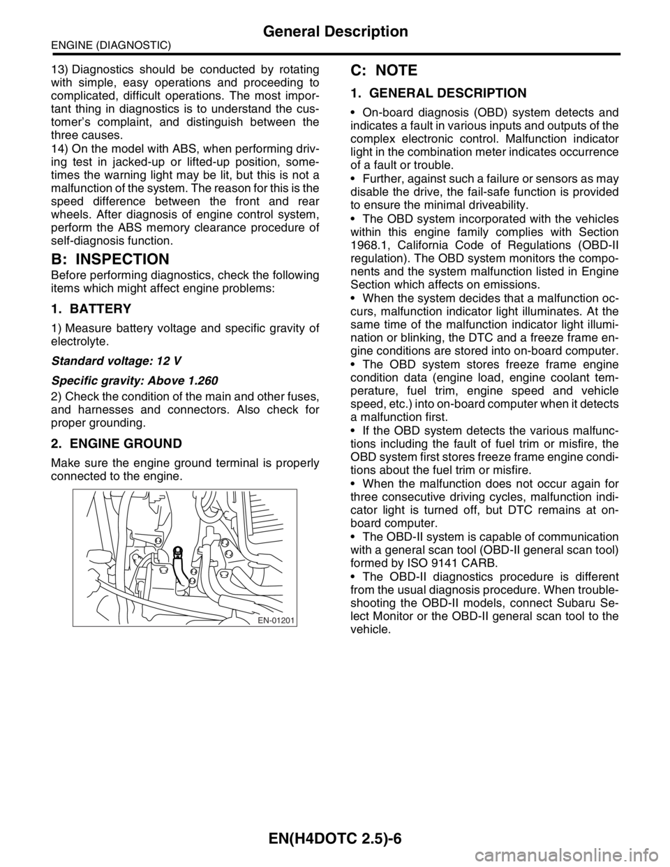
2. ENGINE GROUND
Make sure the engine ground terminal is properly
connected to the engine.
C: NOTE
1. GENERAL DESCRIPTION
On-board diagnosis (OBD) system detects and
indicates a fault in various inputs and outputs of the
complex electronic control. Malfunction indicator
light in the combination meter indicates occurrence
of a fault or trouble.
Further, against such a failure or sensors as may
disable the drive, the fail-safe function is provided
to ensure the minimal driveability.
The OBD system incorporated with the vehicles
within this engine family complies with Section
1968.1, California Code of Regulations (OBD-II
regulation). The OBD system monitors the compo-
nents and the system malfunction listed in Engine
Section which affects on emissions.
When the system decides that a malfunction oc-
curs, malfunction indicator light illuminates. At the
same time of the malfunction indicator light illumi-
nation or blinking, the DTC and a freeze frame en-
gine conditions are stored into on-board computer.
The OBD system stores freeze frame engine
condition data (engine load, engine coolant tem-
perature, fuel trim, engine speed and vehicle
speed, etc.) into on-board computer when it detects
a malfunction first.
If the OBD system detects the various malfunc-
tions including the fault of fuel trim or misfire, the
OBD system first stores freeze frame engine condi-
tions about the fuel trim or misfire.
When the malfunction does not occur again for
three consecutive driving cycles, malfunction indi-
cator light is turned off, but DTC remains at on-
board computer.
The OBD-II system is capable of communication
with a general scan tool (OBD-II general scan tool)
formed by ISO 9141 CARB.
The OBD-II diagnostics procedure is different
from the usual diagnosis procedure. When trouble-
shooting the OBD-II models, connect Subaru Se-
lect Monitor or the OBD-II general scan tool to the
vehicle.
EN-01201
Page 2033 of 2870
EN(H4DOTC 2.5)-9
ENGINE (DIAGNOSTIC)
Electrical Component Location
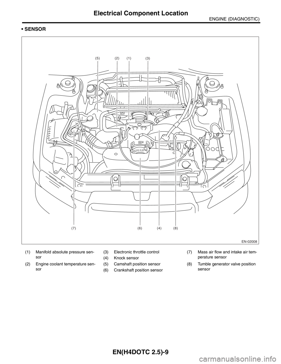
SENSOR
(1) Manifold absolute pressure sen-
sor(3) Electronic throttle control (7) Mass air flow and intake air tem-
perature sensor
(4) Knock sensor
(2) Engine coolant temperature sen-
sor(5) Camshaft position sensor (8) Tumble generator valve position
sensor
(6) Crankshaft position sensor
EN-02008
(1)
(7) (6) (4) (8)(2)
(3)(5)