Page 2316 of 2870
4AT-4
AUTOMATIC TRANSMISSION
General Description
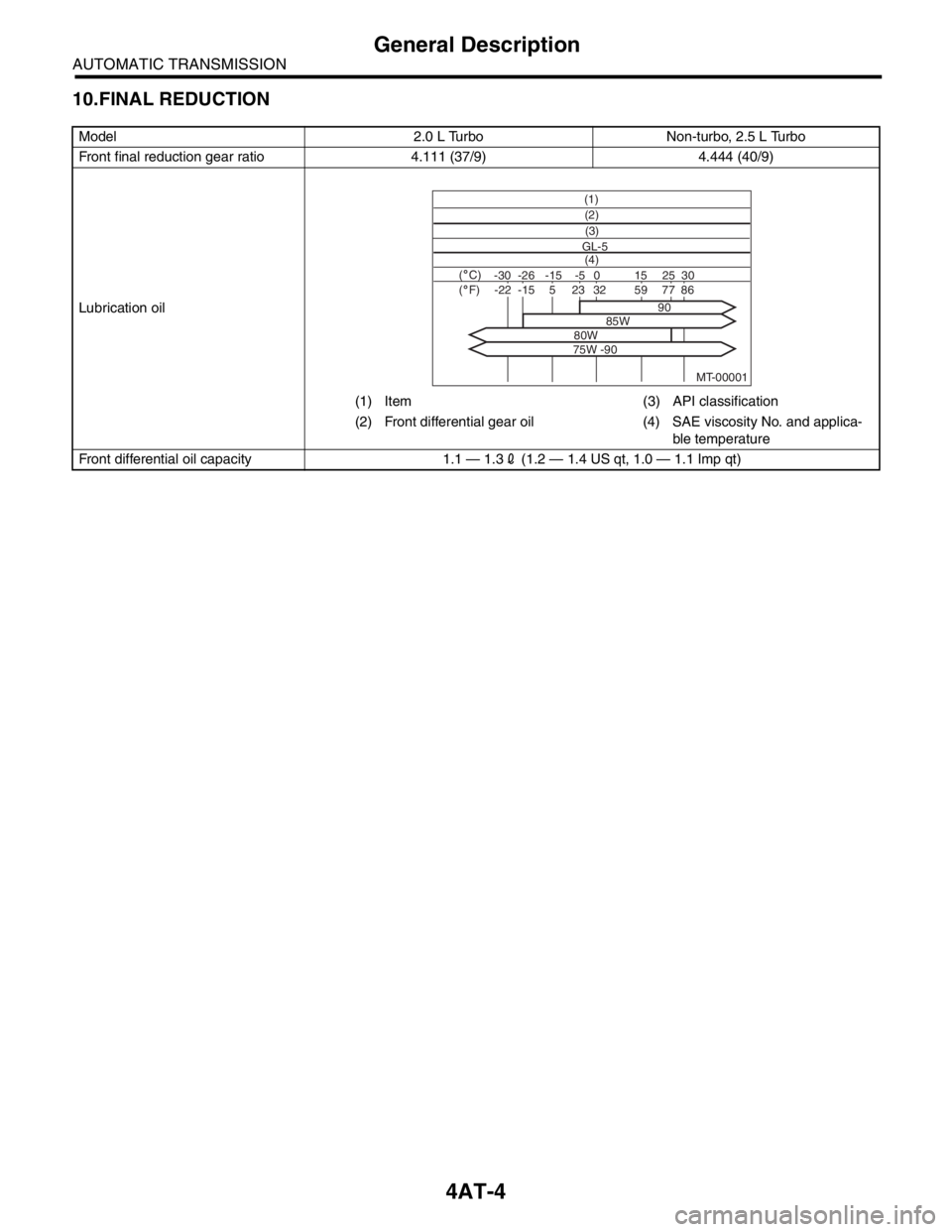
10.FINAL REDUCTION
Model 2.0 L Turbo Non-turbo, 2.5 L Turbo
Front final reduction gear ratio 4.111 (37/9) 4.444 (40/9)
Lubrication oil
(1) Item (3) API classification
(2) Front differential gear oil (4) SAE viscosity No. and applica-
ble temperature
Front differential oil capacity 1.1 — 1.32 (1.2 — 1.4 US qt, 1.0 — 1.1 Imp qt)
MT-00001
(1)
(4) GL-5(3) (2)
( C)( F)-30 -26 -15 15
90
85W
80W
75W -9025 30 -5 0-22-1523328659775
Page 2317 of 2870
4AT-5
AUTOMATIC TRANSMISSION
General Description
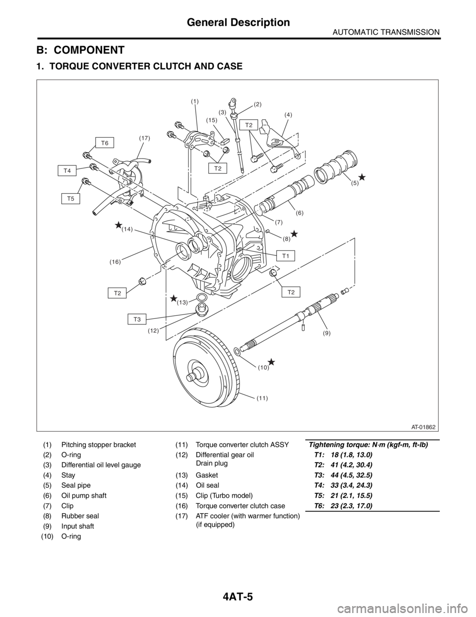
B: COMPONENT
1. TORQUE CONVERTER CLUTCH AND CASE
(1) Pitching stopper bracket (11) Torque converter clutch ASSYTightening torque: N⋅m (kgf-m, ft-lb)
(2) O-ring (12) Differential gear oil
Drain plugT1: 18 (1.8, 13.0)
(3) Differential oil level gaugeT2: 41 (4.2, 30.4)
(4) Stay (13) GasketT3: 44 (4.5, 32.5)
(5) Seal pipe (14) Oil sealT4: 33 (3.4, 24.3)
(6) Oil pump shaft (15) Clip (Turbo model)T5: 21 (2.1, 15.5)
(7) Clip (16) Torque converter clutch caseT6: 23 (2.3, 17.0)
(8) Rubber seal (17) ATF cooler (with warmer function)
(if equipped)
(9) Input shaft
(10) O-ring
AT-01862
T2
T2
T2T2
T3
T1
(8)
(11) (1)
(2)
(3)
(4)
(7)(5)
(6)
(10)(9)
(14)
(16)
(12)
(13)
(15)
T5 T4T6(17)
Page 2318 of 2870
4AT-6
AUTOMATIC TRANSMISSION
General Description
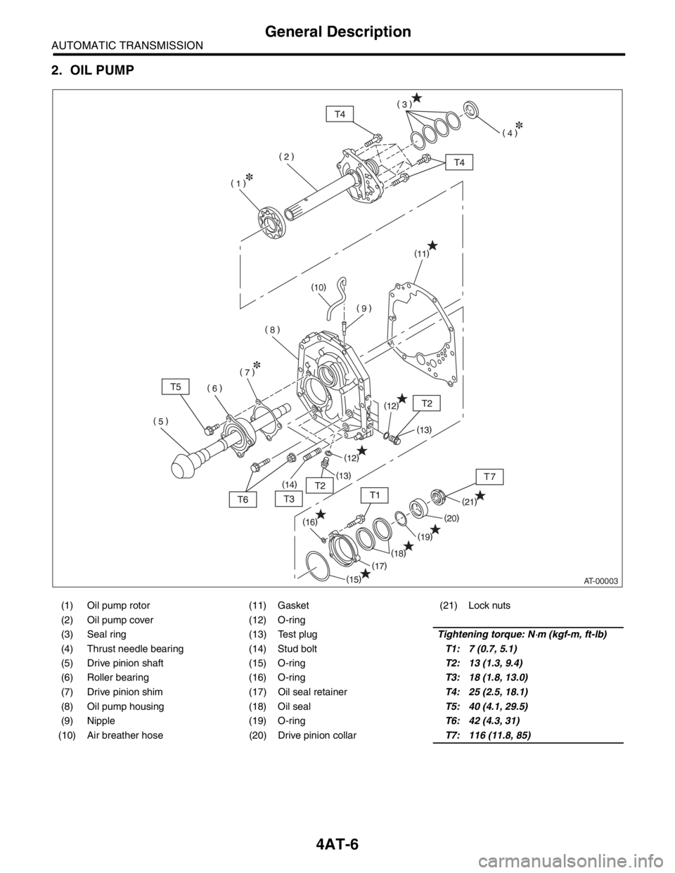
2. OIL PUMP
(1) Oil pump rotor (11) Gasket (21) Lock nuts
(2) Oil pump cover (12) O-ring
(3) Seal ring (13) Test plugTightening torque: N
⋅m (kgf-m, ft-lb)
(4) Thrust needle bearing (14) Stud boltT1: 7 (0.7, 5.1)
(5) Drive pinion shaft (15) O-ringT2: 13 (1.3, 9.4)
(6) Roller bearing (16) O-ringT3: 18 (1.8, 13.0)
(7) Drive pinion shim (17) Oil seal retainerT4: 25 (2.5, 18.1)
(8) Oil pump housing (18) Oil sealT5: 40 (4.1, 29.5)
(9) Nipple (19) O-ringT6: 42 (4.3, 31)
(10) Air breather hose (20) Drive pinion collarT7: 116 (11.8, 85)
AT-00003
Page 2320 of 2870

4AT-8
AUTOMATIC TRANSMISSION
General Description
(1) ATF level gauge (19) Oil filter (41) Transmission case
(2) ATF charger pipe (20) Oil filter stud bolt (42) Plate ASSY
(3) O-ring (21) Drain plug (ATF) (43) Washer
(4) Transfer valve plate (22) Gasket (44) Bushing (turbo model)
(Non-turbo model) (23) Oil pan (45) ATF cooler inlet pipe (model with
ATF cooler (with warmer func-
tion)) (5) Transfer valve ASSY (24) Magnet
(Non-turbo model) (25) Stud bolt (Short)
(6) Transfer clutch seal
(Non-turbo model)(26) Stud bolt (Long) (46) ATF cooler outlet pipe (model
with ATF cooler (with warmer
function)) (27) Parking rod
(7) Transfer duty solenoid (non-turbo
model)(28) Manual plate
(29) Spring pin
(8) Straight pin (30) Detention springTightening torque: N
⋅m (kgf-m, ft-lb)
(9) Return spring (31) BallT1: 3.4 (0.35, 2.6)
(10) Shaft (32) SpringT2: 5 (0.5, 3.6)
(11) Parking pawl (33) GasketT3: 6 (0.6, 4.4)
(12) Parking support (34) ATF cooler outlet pipe (model
without ATF cooler (with warmer
function))T4: 8 (0.8, 6)
(13) Inlet filter (Non-turbo model)T5: 12 (1.2, 8.7)
(14) GasketT6: 13 (1.3, 10)
(15) ATF cooler inlet pipe (model with-
out ATF cooler (with warmer func-
tion))(35) Union screwT7: 14 (1.4, 10)
(36) Oil sealT8: 18 (1.8, 13)
(37) Range select leverT9: 25 (2.5, 18.1)
(16) Union screw (38) Inhibitor switch ASSYT10: 45 (4.6, 33.2)
(17) O-ring (39) NippleT11: 21 (2.1, 15.5)
(18) Test plug (40) Air breather hose
Page 2321 of 2870
4AT-9
AUTOMATIC TRANSMISSION
General Description
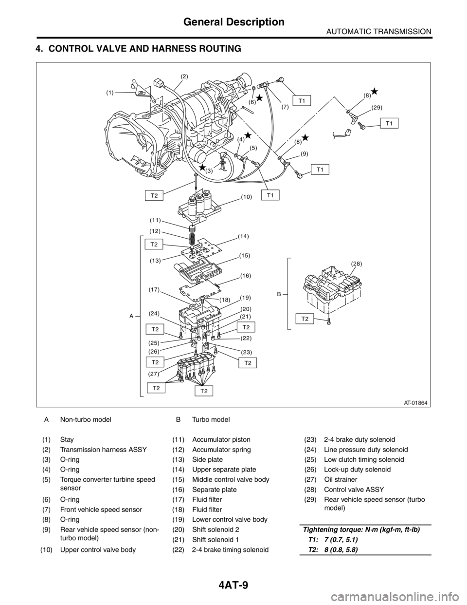
4. CONTROL VALVE AND HARNESS ROUTING
A Non-turbo model B Turbo model
(1) Stay (11) Accumulator piston (23) 2-4 brake duty solenoid
(2) Transmission harness ASSY (12) Accumulator spring (24) Line pressure duty solenoid
(3) O-ring (13) Side plate (25) Low clutch timing solenoid
(4) O-ring (14) Upper separate plate (26) Lock-up duty solenoid
(5) Torque converter turbine speed
sensor(15) Middle control valve body (27) Oil strainer
(16) Separate plate (28) Control valve ASSY
(6) O-ring (17) Fluid filter (29) Rear vehicle speed sensor (turbo
model)
(7) Front vehicle speed sensor (18) Fluid filter
(8) O-ring (19) Lower control valve body
(9) Rear vehicle speed sensor (non-
turbo model)(20) Shift solenoid 2Tightening torque: N
⋅m (kgf-m, ft-lb)
(21) Shift solenoid 1T1: 7 (0.7, 5.1)
(10) Upper control valve body (22) 2-4 brake timing solenoidT2: 8 (0.8, 5.8)
AT-01864
T1T2
T2
T2
T2
T2
T2
T2T2
T2
T1
(1)(2)
(3)(4)
(5)
(6)
(7)
(10)
(11)
(12)
(14)
(13)(15)
(16)
(17)
A(24)(19)
(18)
(20)
(21)
(22)
(23) (26) (25)
(27)
(28)
B
T1
(8)
(9)
T1
(8)
(29)
Page 2326 of 2870
4AT-14
AUTOMATIC TRANSMISSION
General Description
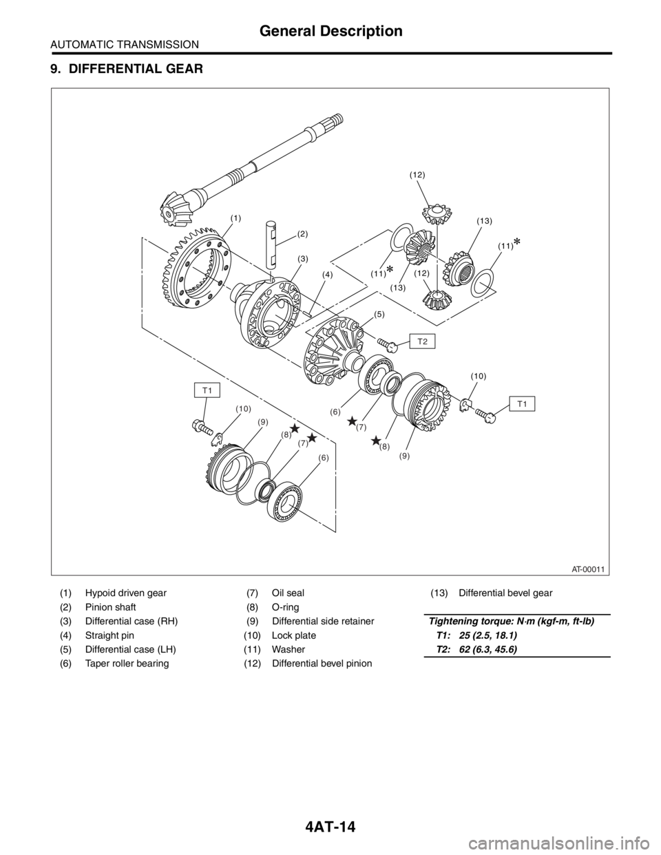
9. DIFFERENTIAL GEAR
(1) Hypoid driven gear (7) Oil seal (13) Differential bevel gear
(2) Pinion shaft (8) O-ring
(3) Differential case (RH) (9) Differential side retainerTightening torque: N
⋅m (kgf-m, ft-lb)
(4) Straight pin (10) Lock plateT1: 25 (2.5, 18.1)
(5) Differential case (LH) (11) WasherT2: 62 (6.3, 45.6)
(6) Taper roller bearing (12) Differential bevel pinion
AT-00011
T2
T1
T1
(8) (8)
(9) (9)
(7)
(7)(6)
(6)
(10)
(13)
(13) (1)
(2)
(3)
(4)
(5)
(10)(11)
(11)(12) (12)
Page 2327 of 2870
4AT-15
AUTOMATIC TRANSMISSION
General Description
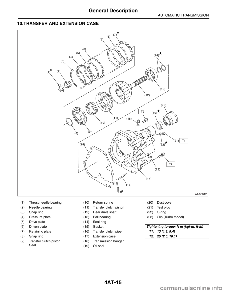
10.TRANSFER AND EXTENSION CASE
(1) Thrust needle bearing (10) Return spring (20) Dust cover
(2) Needle bearing (11) Transfer clutch piston (21) Test plug
(3) Snap ring (12) Rear drive shaft (22) O-ring
(4) Pressure plate (13) Ball bearing (23) Clip (Turbo model)
(5) Drive plate (14) Seal ring
(6) Driven plate (15) GasketTightening torque: N
⋅m (kgf-m, ft-lb)
(7) Retaining plate (16) Transfer clutch pipeT1: 13 (1.3, 9.4)
(8) Snap ring (17) Extension caseT2: 25 (2.5, 18.1)
(9) Transfer clutch piston
Seal(18) Transmission hanger
(19) Oil seal
AT-00012
(1)(2)(3)(4)(5)(6)(7)
(8)(9)(10)(11)
(16)(23) (18)(19)
(22)(21) (12)(13) (14)
(15)
(5)
(17)
(20)
T2
T2
T1
(6)
Page 2330 of 2870

4AT-18
AUTOMATIC TRANSMISSION
General Description
C: CAUTION
Wear work clothing, including a cap, protective
goggles, and protective shoes during operation.
Remove contamination including dirt and corro-
sion before removal, installation or disassembly.
Keep the disassembled parts in order and pro-
tect them from dust and dirt.
Until the oil pan is installed, do not place with the
inside of oil pan facing up to prevent foreign matter
from entering the valve body.
Before removal, installation or disassembly, be
sure to clarify the failure. Avoid unnecessary re-
moval, installation, disassembly and replacement.
When disassembling the case and other light al-
loy parts, use a plastic hammer to force it apart. Do
not pry it apart with a screwdriver or other tool.
Be careful not to burn yourself, because each
part on the vehicle is hot after running.
Use SUBARU genuine gear oil, grease etc. or
the equivalent. Do not mix gear oil, grease etc. with
that of another grade or from other manufacturers.
Be sure to tighten fasteners including bolts and
nuts to the specified torque.
Place shop jacks or rigid racks at the specified
points.
Apply gear oil or ATF onto sliding or revolution
surfaces before installation.
Replace deformed or otherwise damaged snap
rings with new ones.
Before installing O-rings or oil seals, apply suffi-
cient amount of ATF to avoid damage and defor-
mation.
Be careful not to incorrectly install or fail to install
O-rings, snap rings and other such parts.
Before securing a part on a vice, place cushion-
ing material such as wood blocks, aluminum plate,
or shop cloth between the part and the vice.
Avoid damaging the mating surface of the case.
Before applying sealant, completely remove the
old seal.