Page 2307 of 2870
CS-22
CONTROL SYSTEM
MT Gear Shift Lever
E: INSPECTION
1) Check each part (bushing, cushion rubber, spacer,
boot, stay, rod, etc.) for deformation, damage and
wear. Repair or replace any defective part. Determine
defective parts by comparing with new parts.
2) Check the swing torque of the rod connected to
gear shift lever.
If the torque exceeds specification, replace the
bushing or retighten nuts.
Swing torque:
3.7 N (0.38 kgf, 0.83 lb) or less3) Check that there is no excessive play and that
parts move smoothly.
(A) Bushing
(B) Cushion rubber
(C) Spacer
(D) Boot
(E) Stay
(F) Rod
(A) Center of rotation
(B) Swing torque
(C)
(D)(A) (F) (A)
CS-00064
(E)(B)
CS-00065
(A)
(B)
Page 2747 of 2870

5MT-35
MANUAL TRANSMISSION AND DIFFERENTIAL
Manual Transmission Assembly
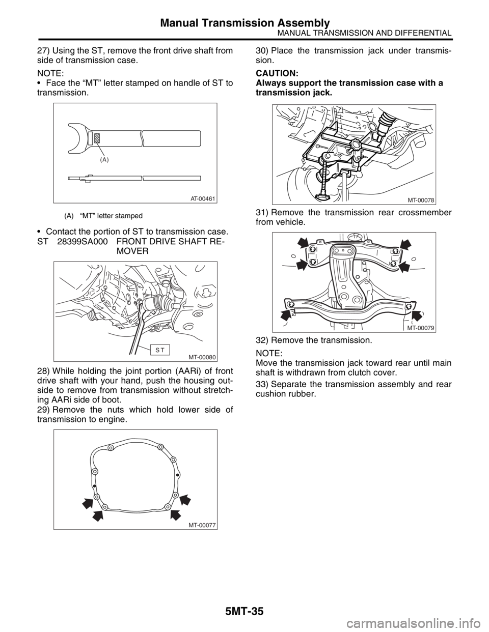
27) Using the ST, remove the front drive shaft from
side of transmission case.
NOTE:
Face the “MT” letter stamped on handle of ST to
transmission.
Contact the portion of ST to transmission case.
ST 28399SA000 FRONT DRIVE SHAFT RE-
MOVER
28) While holding the joint portion (AARi) of front
drive shaft with your hand, push the housing out-
side to remove from transmission without stretch-
ing AARi side of boot.
29) Remove the nuts which hold lower side of
transmission to engine.30) Place the transmission jack under transmis-
sion.
CAUTION:
Always support the transmission case with a
transmission jack.
31) Remove the transmission rear crossmember
from vehicle.
32) Remove the transmission.
NOTE:
Move the transmission jack toward rear until main
shaft is withdrawn from clutch cover.
33) Separate the transmission assembly and rear
cushion rubber.
(A) “MT” letter stamped
AT-00461
(A)
MT-00080ST
MT-00077
MT-00078
MT-00079
Page 2835 of 2870
CL-9
CLUTCH SYSTEM
General Description
4. MASTER CYLINDER
NON-TURBO MODEL
(1) Reservoir cap (7) GasketTightening torque: N⋅m (kgf-m, ft-lb)
(2) Reservoir tank (8) Return springT1: 10 (1.0, 7)
(3) Oil seal (9) PistonT2: 46.6 (4.75, 34.4)
(4) Straight pin (10) Push rod
(5) Master cylinder (11) Piston stop ring
(6) Clutch damper (12) Cylinder boot
CL-00005
(1)
(2)
(3)
(4)
(5)
(7)
(6)
T2
T1
(8)
(9)(10) (11)
(12)
Page 2836 of 2870
CL-10
CLUTCH SYSTEM
General Description
LHD TURBO MODEL
(1) Reservoir cap (7) GasketTightening torque: N⋅m (kgf-m, ft-lb)
(2) Reservoir tank (8) Return springT1: 10 (1.0, 7)
(3) Oil seal (9) PistonT2: 46.6 (4.75, 34.4)
(4) Straight pin (10) Push rod
(5) Master cylinder (11) Piston stop ring
(6) Clutch damper (12) Cylinder boot
CL-00109
(3)(1)
(4)
(5)
T1
(8)
(9)(11)(12)
(10)
(2)
(7)
(6)
T2
Page 2837 of 2870
CL-11
CLUTCH SYSTEM
General Description
RHD TURBO MODEL
(1) Reservoir cap (8) Oil sealTightening torque: N⋅m (kgf-m, ft-lb)
(2) Reservoir tank (9) Master cylinderT1: 8 (0.8, 5.8)
(3) Washer (10) Return springT2: 10 (1.0, 7)
(4) Straight pin (11) PistonT3: 18 (1.8, 13.0)
(5) Clip (12) Push rod
(6) Hose (13) Piston stop ring
(7) Reservoir tank bracket (14) Cylinder boot
)
CL-00162
(8) (1)
(2)
(9)
T2
(10)
(11)(13)
(12) (14)
T1
T3
T3
(7)
(5)
(3) (3)
(6)
(5)
(4)
Page 2851 of 2870

CL-25
CLUTCH SYSTEM
Operating Cylinder
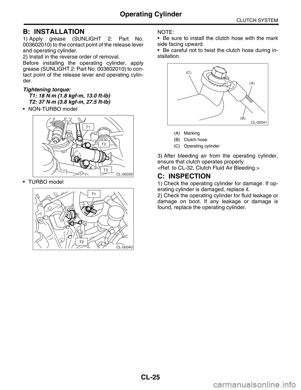
B: INSTALLATION
1) Apply grease (SUNLIGHT 2: Part No.
003602010) to the contact point of the release lever
and operating cylinder.
2) Install in the reverse order of removal.
Before installing the operating cylinder, apply
grease (SUNLIGHT 2: Part No. 003602010) to con-
tact point of the release lever and operating cylin-
der.
Tightening torque:
T1: 18 N
⋅m (1.8 kgf-m, 13.0 ft-lb)
T2: 37 N
⋅m (3.8 kgf-m, 27.5 ft-lb)
NON-TURBO model
TURBO modelNOTE:
Be sure to install the clutch hose with the mark
side facing upward.
Be careful not to twist the clutch hose during in-
stallation.
3) After bleeding air from the operating cylinder,
ensure that clutch operates properly.
C: INSPECTION
1) Check the operating cylinder for damage. If op-
erating cylinder is damaged, replace it.
2) Check the operating cylinder for fluid leakage or
damage on boot. If any leakage or damage is
found, replace the operating cylinder.
T2
CL-00039T2
T1
CL-00040
T2
T1
(A) Marking
(B) Clutch hose
(C) Operating cylinder
CL-00041
(A)
(B) (C)
Page 2853 of 2870
CL-27
CLUTCH SYSTEM
Master Cylinder
C: DISASSEMBLY
1. EXCEPT RHD TURBO MODEL
1) Remove the straight pin and reservoir tank.
2) Remove the oil seal.
3) Move the cylinder boot backward.
4) Remove the stop ring.
CAUTION:
Be careful when removing the stop ring to pre-
vent the rod, washer, piston and return spring
from flying out.
2. RHD TURBO MODEL
1) Remove the hose.
2) Remove the reservoir tank and bracket.
3) Remove the straight pin and adapter.
4) Remove the oil seal.
(A) Reservoir tank
(B) Straight pin
(A) Oil seal
(B) Master cylinder
(A) Cylinder boot
(B) Master cylinder
CL-00046
(A)
(B)
CL-00047
(A)
(B)
CL-00048
(A)
(B)
(A) Reservoir tank
(B) Bracket
(A) Straight pin
(B) Adapter
CL-00049
CL-00050
(A)(B)
CL-00051 (A)(B)
CL-00052
Page 2854 of 2870

CL-28
CLUTCH SYSTEM
Master Cylinder
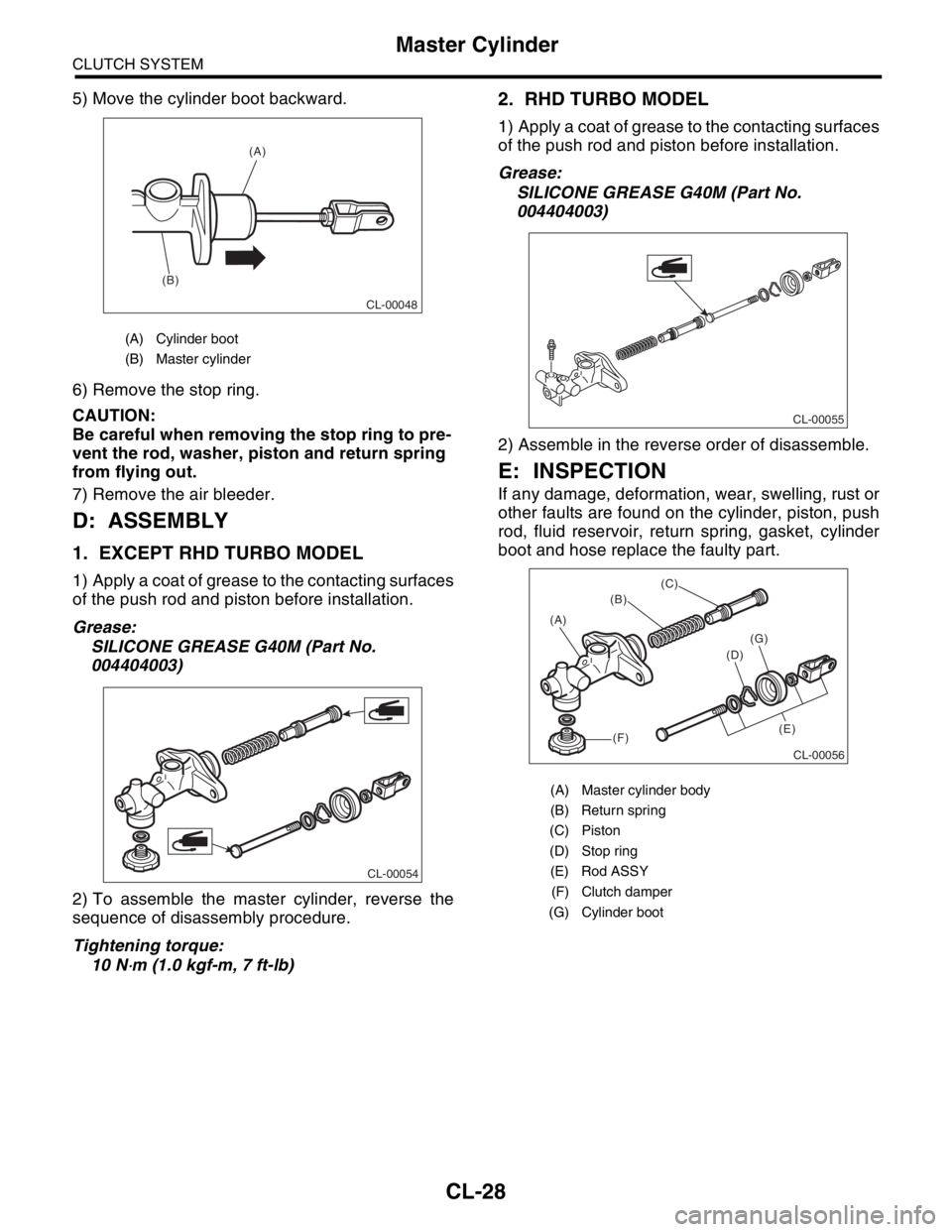
5) Move the cylinder boot backward.
6) Remove the stop ring.
CAUTION:
Be careful when removing the stop ring to pre-
vent the rod, washer, piston and return spring
from flying out.
7) Remove the air bleeder.
D: ASSEMBLY
1. EXCEPT RHD TURBO MODEL
1) Apply a coat of grease to the contacting surfaces
of the push rod and piston before installation.
Grease:
SILICONE GREASE G40M (Part No.
004404003)
2) To assemble the master cylinder, reverse the
sequence of disassembly procedure.
Tightening torque:
10 N
⋅m (1.0 kgf-m, 7 ft-lb)
2. RHD TURBO MODEL
1) Apply a coat of grease to the contacting surfaces
of the push rod and piston before installation.
Grease:
SILICONE GREASE G40M (Part No.
004404003)
2) Assemble in the reverse order of disassemble.
E: INSPECTION
If any damage, deformation, wear, swelling, rust or
other faults are found on the cylinder, piston, push
rod, fluid reservoir, return spring, gasket, cylinder
boot and hose replace the faulty part.
(A) Cylinder boot
(B) Master cylinder
CL-00048
(A)
(B)
CL-00054
(A) Master cylinder body
(B) Return spring
(C) Piston
(D) Stop ring
(E) Rod ASSY
(F) Clutch damper
(G) Cylinder boot
CL-00055
CL-00056
(B)
(C)
(D)
(E) (A)
(F)
(G)