Page 1446 of 2870
IN(H4DOTC)-7
INTAKE (INDUCTION)
Air Cleaner
2. Air Cleaner
A: REMOVAL
1) Disconnect the ground cable from battery.
2) Disconnect the connector from mass air flow
sensor.
3) Loosen the clamp (A) which connects air intake
boot and intake duct.
4) Remove the clip (B) from air cleaner upper cover.
5) Remove the air cleaner upper cover.
6) Remove the air cleaner element.
7) Remove the air cleaner lower case.
B: INSTALLATION
Install in the reverse order of removal.
Tightening torque:
33 N
⋅m (3.4 kgf-m, 24.6 ft-lb)
NOTE:
Before installing the air cleaner upper cover, align
the holes with protruding portions of air cleaner
lower case, then secure the upper cover to lower
case.
C: INSPECTION
Replace if excessively damaged or dirty.
FU-00009
IN-00005
IN-00006
(B)
(A)
IN-00007
IN-00007
IN-00008
Page 1944 of 2870

FU(H4DOTC 2.5)-14
FUEL INJECTION (FUEL SYSTEM)
Intake Manifold
3. Intake Manifold
A: REMOVAL
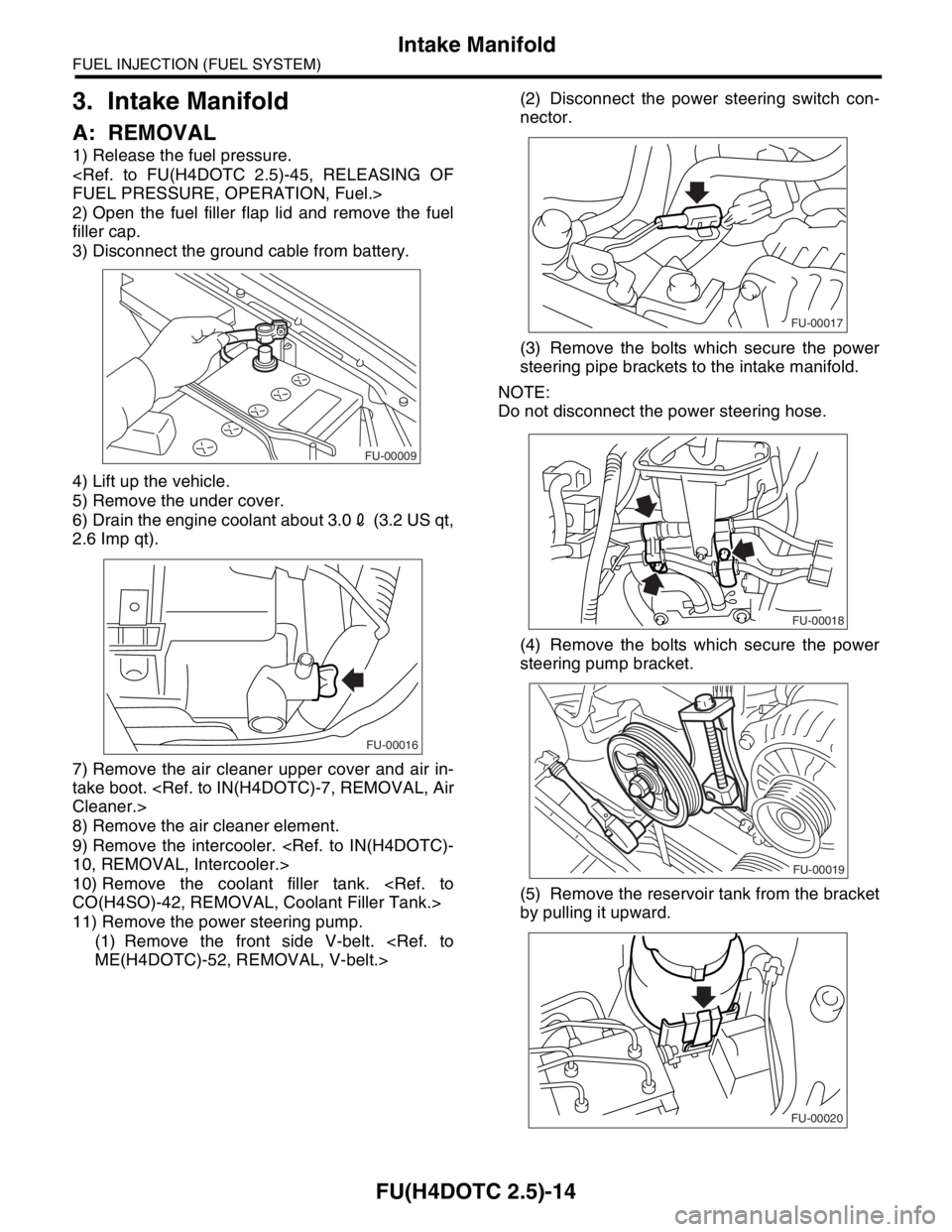
1) Release the fuel pressure.
FUEL PRESSURE, OPERATION, Fuel.>
2) Open the fuel filler flap lid and remove the fuel
filler cap.
3) Disconnect the ground cable from battery.
4) Lift up the vehicle.
5) Remove the under cover.
6) Drain the engine coolant about 3.02 (3.2 US qt,
2.6 Imp qt).
7) Remove the air cleaner upper cover and air in-
take boot.
Cleaner.>
8) Remove the air cleaner element.
9) Remove the intercooler.
10, REMOVAL, Intercooler.>
10) Remove the coolant filler tank.
CO(H4SO)-42, REMOVAL, Coolant Filler Tank.>
11) Remove the power steering pump.
(1) Remove the front side V-belt.
ME(H4DOTC)-52, REMOVAL, V-belt.>(2) Disconnect the power steering switch con-
nector.
(3) Remove the bolts which secure the power
steering pipe brackets to the intake manifold.
NOTE:
Do not disconnect the power steering hose.
(4) Remove the bolts which secure the power
steering pump bracket.
(5) Remove the reservoir tank from the bracket
by pulling it upward.
FU-00009
FU-00016
FU-00017
FU-00018
FU-00019
FU-00020
Page 2290 of 2870
CS-5
CONTROL SYSTEM
General Description
2. MT GEAR SHIFT LEVER
(1) Gear shift knob (11) Bushing A (21) Boot & insulator ASSY
(2) Console boot (12) Spring pin (22) Front cover
(3) Plate ASSY (13) Cushion rubber (23) Clamp
(4) Gear shift lever (14) Bushing B
(5) Bushing (15) JointTightening torque: N·m (kgf-m, ft-lb)
(6) Bushing (16) RodT1: 7.5 (0.76, 5.5)
(7) Lock wire (17) BracketT2: 12 (1.2, 8.7)
(8) Boot (18) WasherT3: 18 (1.8, 13.0)
(9) Snap ring (19) Stay
(10) O-ring (20) Spacer
CS-00357
T2
(5) (5)
(5) (5)
(4)
(6)(3) (2)(1)
(18)(21)(23) (22)
(20)
(19)(17)T1
(14)
(13) (16)
(15)
(12) (12)
(11)
(10)
(10)
(9)(8)
(7)
T3
T3
T3
T3
Page 2299 of 2870

CS-14
CONTROL SYSTEM
Select Cable
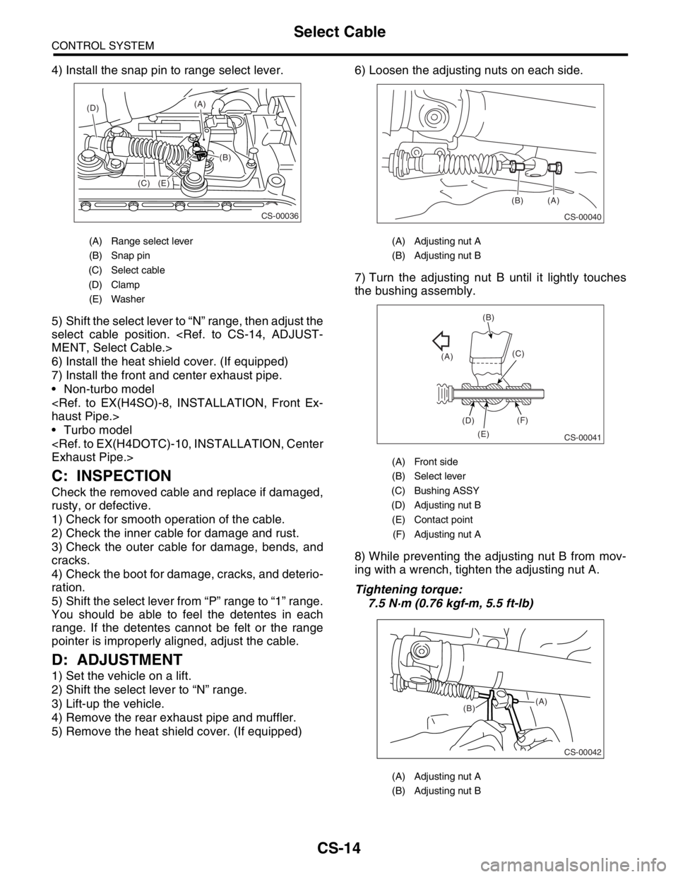
4) Install the snap pin to range select lever.
5) Shift the select lever to “N” range, then adjust the
select cable position.
MENT, Select Cable.>
6) Install the heat shield cover. (If equipped)
7) Install the front and center exhaust pipe.
Non-turbo model
haust Pipe.>
Turbo model
Exhaust Pipe.>
C: INSPECTION
Check the removed cable and replace if damaged,
rusty, or defective.
1) Check for smooth operation of the cable.
2) Check the inner cable for damage and rust.
3) Check the outer cable for damage, bends, and
cracks.
4) Check the boot for damage, cracks, and deterio-
ration.
5) Shift the select lever from “P” range to “1” range.
You should be able to feel the detentes in each
range. If the detentes cannot be felt or the range
pointer is improperly aligned, adjust the cable.
D: ADJUSTMENT
1) Set the vehicle on a lift.
2) Shift the select lever to “N” range.
3) Lift-up the vehicle.
4) Remove the rear exhaust pipe and muffler.
5) Remove the heat shield cover. (If equipped)6) Loosen the adjusting nuts on each side.
7) Turn the adjusting nut B until it lightly touches
the bushing assembly.
8) While preventing the adjusting nut B from mov-
ing with a wrench, tighten the adjusting nut A.
Tightening torque:
7.5 N·m (0.76 kgf-m, 5.5 ft-lb)
(A) Range select lever
(B) Snap pin
(C) Select cable
(D) Clamp
(E) Washer
CS-00036
(C)(B) (A)
(E) (D)
(A) Adjusting nut A
(B) Adjusting nut B
(A) Front side
(B) Select lever
(C) Bushing ASSY
(D) Adjusting nut B
(E) Contact point
(F) Adjusting nut A
(A) Adjusting nut A
(B) Adjusting nut B
CS-00040
(A) (B)
CS-00041
(A)(B)
(C)
(D)
(E)(F)
CS-00042
(A)
(B)
Page 2302 of 2870
CS-17
CONTROL SYSTEM
MT Gear Shift Lever
5. MT Gear Shift Lever
A: REMOVAL
1) Set the vehicle on a lift.
2) Remove the gear shift knob.
3) Disconnect the ground cable from battery.
4) Remove the console box.
MOVAL, Console Box.>
5) Remove the clamp.
6) Remove the boot & insulator assembly.
7) Remove the drive select cable.
REMOVAL, Drive Select Cable.>
8) Remove the plate assembly from body.
9) Lift-up the vehicle.
10) Remove the rear exhaust pipe and muffler. Non-turbo model
Pipe.>
fler.>
Turbo model
haust Pipe.>
AL, Muffler.>
11) Remove the heat shield cover. (If equipped)
12) Remove the stay from transmission bracket.
13) Remove the rod from joint.
14) Remove the cushion rubber from body.
CS-00099
CS-00100
CS-00101
(A) Stay
(B) Transmission bracket
(A) Stay
(B) Rod
(A) Stay
(B) Cushion rubber
CS-00050
(A)
(B)
CS-00051
(A)
(B)
CS-00052
(A)
(B)
Page 2304 of 2870
CS-19
CONTROL SYSTEM
MT Gear Shift Lever
6) Connect the stay to transmission bracket.
Tightening torque:
18 N·m (1.8 kgf-m, 13.0 ft-lb)
7) Install the heat shield cover. (If equipped)
8) Install the rear exhaust pipe and muffler.
Non-turbo model
haust Pipe.>
TION, Muffler.>
Turbo model
Exhaust Pipe.>
STALLATION, Muffler.>
9) Lower the vehicle.
10) Install the plate assembly to body.
Tightening torque:
7.5 N·m (0.76 kgf-m, 5.5 ft-lb)
11) Install the drive select cable.
INSTALLATION, Drive Select Cable.>12) Install the boot and insulator assembly to the
vehicle in proper direction.
13) Install the clamp.
14) Install the console box.
LATION, Console Box.>
C: DISASSEMBLY
1) Remove the lock wire.
2) Remove the rod from gear shift lever.
(A) Stay
(B) Transmission bracket
CS-00050
(A)
(B)
CS-00101
(A) Lock wire
(B) Stay
(A) Rod
(B) Gear shift lever
(C) Stay
CS-00100
CS-00055
(B)
(A)
CS-00056
(A)
(B)
(C)
Page 2305 of 2870
CS-20
CONTROL SYSTEM
MT Gear Shift Lever
3) Remove the snap ring from bushing B, and then
disconnect the stay.
4) Remove the boot from gear shift lever.
5) Remove the bushing and cushion rubber from
stay.
6) Remove the O-ring, and then remove the bush-
ing B.7) Draw out the spring pin, and then remove the
bushing A from gear shift lever.
D: ASSEMBLY
1) Clean all parts before assembly.
2) Mount the bushing and cushion rubber on the
stay.
(A) Snap ring
(B) Bushing B
(C) Stay
(A) Bushing
(B) Stay
(C) Cushion rubber
(A) O-ring
(B) O-ring
(C) Bushing B
CS-00057
(A)(B)
(C)
CS-00058
(A)
(B)
(C)
CS-00059
(C)
(B)
(A)
(A) Spring pin
(B) Bushing A
(A) Bushing
(B) Cushion rubber
CS-00060
(B)
(A)
CS-00061
(A)
(B)
Page 2306 of 2870
CS-21
CONTROL SYSTEM
MT Gear Shift Lever
3) Mount each part; boot, O-ring, bushing A, spac-
er, bushing B, bushing and spring pin on the gear
shift lever.
NOTE:
Always use new O-rings.
Apply grease [SUNLIGHT 2 (Part No. 003602010)
or equivalent] to the inner and side surfaces of the
bush when installing the spacer.
4) Insert the gear shift lever into boot hole.
5) Install the snap ring and stay to bushing B.6) Tighten with a lock wire to the extent that the
boot will not come off.
NOTE:
Always use new lock wire.
7) Insert the rod into boot hole.
8) Connect the rod to gear shift lever.
Tightening torque:
12 N·m (1.2 kgf-m, 8.7 ft-lb)
(A) Boot
(B) O-ring
(C) Bushing
(D) Spacer
(E) Bushing A
(F) Bushing B
(G) Spring pin
(H) O-ring
(A) Snap ring
(B) Bushing B
CS-00062
(F)(D)(C)
(E)
(G)
(H)
(B)
(A)
CS-00165
(A)(B)
(A) Lock wire
(B) Stay
(A) Rod
(B) Gear shift lever
(C) Stay
CS-00055
(B)
(A)
CS-00056
(A)
(B)
(C)