Page 1557 of 2870

ME(H4DOTC)-97
MECHANICAL
Cylinder Block
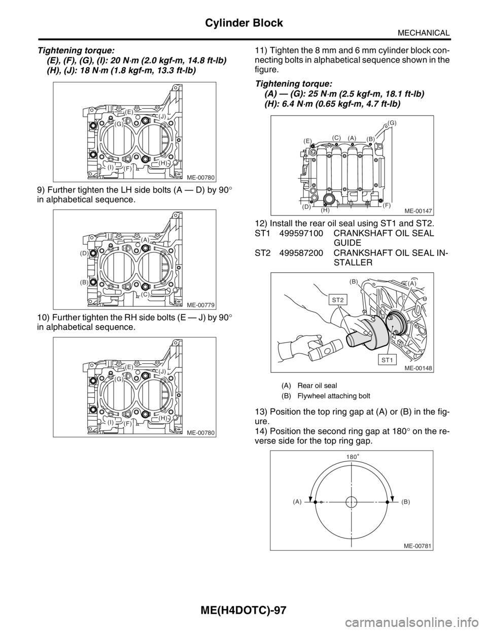
Tightening torque:
(E), (F), (G), (I): 20 N
⋅m (2.0 kgf-m, 14.8 ft-lb)
(H), (J): 18 N
⋅m (1.8 kgf-m, 13.3 ft-lb)
9) Further tighten the LH side bolts (A — D) by 90°
in alphabetical sequence.
10) Further tighten the RH side bolts (E — J) by 90°
in alphabetical sequence.11) Tighten the 8 mm and 6 mm cylinder block con-
necting bolts in alphabetical sequence shown in the
figure.
Tightening torque:
(A) — (G): 25 N
⋅m (2.5 kgf-m, 18.1 ft-lb)
(H): 6.4 N
⋅m (0.65 kgf-m, 4.7 ft-lb)
12) Install the rear oil seal using ST1 and ST2.
ST1 499597100 CRANKSHAFT OIL SEAL
GUIDE
ST2 499587200 CRANKSHAFT OIL SEAL IN-
STALLER
13) Position the top ring gap at (A) or (B) in the fig-
ure.
14) Position the second ring gap at 180° on the re-
verse side for the top ring gap.
ME-00780
(J)
(H)
(G)
(E)
(F)(I)
ME-00779
(A)
(B)
(D)
(C)
ME-00780
(J)
(H)
(G)
(E)
(F)(I)
(A) Rear oil seal
(B) Flywheel attaching bolt
ME-00147
(B)(C)
(D)
(E)
(F)
(G)
(H)
(A)
ME-00148
ST1
ST2
(B)
(A)
ME-00781
(A)(B) 180
Page 1583 of 2870

ME(H4DOTC)-123
MECHANICAL
Engine Noise
26.Engine Noise
A: INSPECTION
NOTE*:
When disconnecting the fuel injector connector, Malfunction Indicator Light illuminates and DTC is stored in
ECM memory.
Therefore, carry out the CLEAR MEMORY MODE
Mode.> and INSPECTION MODE after con-
necting the fuel injector connector.
Type of sound Condition Possible cause
Regular clicking soundSound increases as engine
speed increases. Valve mechanism is defective.
Incorrect valve clearance
Worn valve rocker
Worn camshaft
Broken valve spring
Heavy and dull clankOil pressure is low. Worn crankshaft main bearing
Worn connecting rod bearing (big end)
Oil pressure is normal. Loose flywheel mounting bolts
Damaged engine mounting
High-pitched clank (Spark
knock)Sound is noticeable when
accelerating with an overload. Ignition timing advanced
Accumulation of carbon inside combustion chamber
Wrong heat range of spark plug
Improper octane number of gasoline
Clank when engine speed is
medium (1,000 to 2,000 rpm).Sound is reduced when fuel
injector connector of noisy cyl-
inder is disconnected.
(NOTE*) Worn crankshaft main bearing
Worn bearing at crankshaft end of connecting rod
Knocking sound when engine
is operating under idling speed
and engine is warmSound is reduced when fuel
injector connector of noisy cyl-
inder is disconnected.
(NOTE*) Worn cylinder liner and piston ring
Broken or stuck piston ring
Worn piston pin and hole at piston end of connecting rod
Sound is not reduced if each
fuel injector connector is dis-
connected in turn. (NOTE*) Unusually worn valve lifter
Worn cam gear
Worn camshaft journal bore in crankcase
Squeaky sound — Insufficient generator lubrication
Rubbing sound — Defective generator brush and rotor contact
Gear scream when starting
engine— Defective ignition starter switch
Worn gear and starter pinion
Sound like polishing glass with
a dry cloth— Loose drive belt
Defective water pump shaft
Hissing sound — Loss of compression
Air leakage in air intake system, hoses, connections or mani-
folds
Timing belt noise — Loose timing belt
Belt contacting case/adjacent part
Valve tappet noise — Incorrect valve clearance
Page 1598 of 2870

EX(H4DOTC)-12
EXHAUST
Center Exhaust Pipe
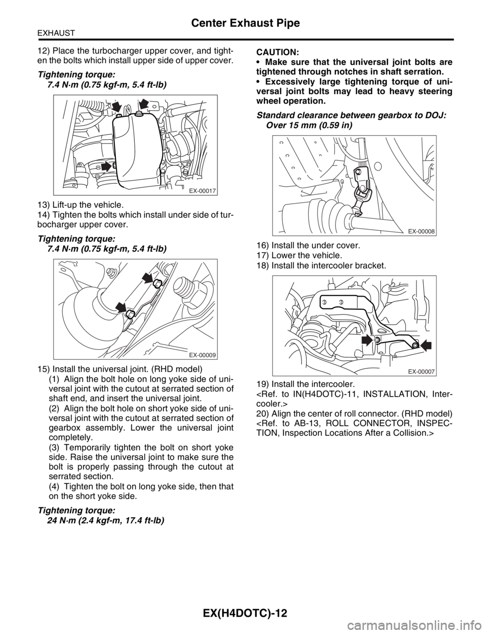
12) Place the turbocharger upper cover, and tight-
en the bolts which install upper side of upper cover.
Tightening torque:
7.4 N·m (0.75 kgf-m, 5.4 ft-lb)
13) Lift-up the vehicle.
14) Tighten the bolts which install under side of tur-
bocharger upper cover.
Tightening torque:
7.4 N·m (0.75 kgf-m, 5.4 ft-lb)
15) Install the universal joint. (RHD model)
(1) Align the bolt hole on long yoke side of uni-
versal joint with the cutout at serrated section of
shaft end, and insert the universal joint.
(2) Align the bolt hole on short yoke side of uni-
versal joint with the cutout at serrated section of
gearbox assembly. Lower the universal joint
completely.
(3) Temporarily tighten the bolt on short yoke
side. Raise the universal joint to make sure the
bolt is properly passing through the cutout at
serrated section.
(4) Tighten the bolt on long yoke side, then that
on the short yoke side.
Tightening torque:
24 N·m (2.4 kgf-m, 17.4 ft-lb)CAUTION:
Make sure that the universal joint bolts are
tightened through notches in shaft serration.
Excessively large tightening torque of uni-
versal joint bolts may lead to heavy steering
wheel operation.
Standard clearance between gearbox to DOJ:
Over 15 mm (0.59 in)
16) Install the under cover.
17) Lower the vehicle.
18) Install the intercooler bracket.
19) Install the intercooler.
cooler.>
20) Align the center of roll connector. (RHD model)
TION, Inspection Locations After a Collision.>
EX-00017
EX-00009
EX-00008
EX-00007
Page 2842 of 2870

CL-16
CLUTCH SYSTEM
Clutch Disc and Cover
2. Clutch Disc and Cover
A: REMOVAL
1) Remove the transmission assembly from vehicle
body.
mission Assembly.>
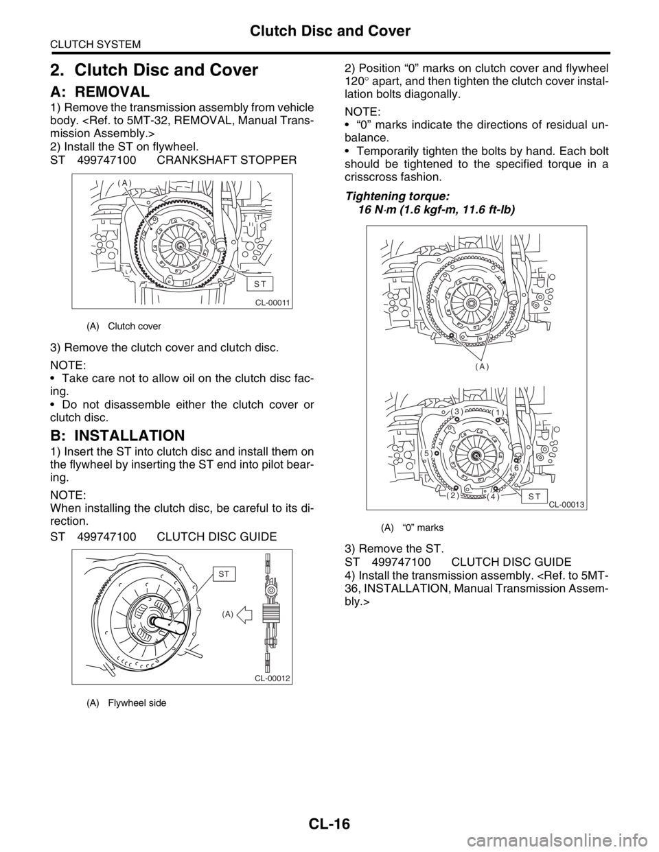
2) Install the ST on flywheel.
ST 499747100 CRANKSHAFT STOPPER
3) Remove the clutch cover and clutch disc.
NOTE:
Take care not to allow oil on the clutch disc fac-
ing.
Do not disassemble either the clutch cover or
clutch disc.
B: INSTALLATION
1) Insert the ST into clutch disc and install them on
the flywheel by inserting the ST end into pilot bear-
ing.
NOTE:
When installing the clutch disc, be careful to its di-
rection.
ST 499747100 CLUTCH DISC GUIDE2) Position “0” marks on clutch cover and flywheel
120° apart, and then tighten the clutch cover instal-
lation bolts diagonally.
NOTE:
“0” marks indicate the directions of residual un-
balance.
Temporarily tighten the bolts by hand. Each bolt
should be tightened to the specified torque in a
crisscross fashion.
Tightening torque:
16 N
⋅m (1.6 kgf-m, 11.6 ft-lb)
3) Remove the ST.
ST 499747100 CLUTCH DISC GUIDE
4) Install the transmission assembly.
36, INSTALLATION, Manual Transmission Assem-
bly.>
(A) Clutch cover
(A) Flywheel side
CL-00011
(A)
ST
CL-00012
(A)
ST
(A) “0” marks
CL-00013 (A)ST(2)
(5)
(3)(1)
(6)
(4)
Page 2845 of 2870

CL-19
CLUTCH SYSTEM
Flywheel
3. Flywheel
A: REMOVAL
1) Remove the transmission assembly.
5MT-32, REMOVAL, Manual Transmission As-
sembly.>
2) Remove the clutch cover and clutch disc.
to CL-16, REMOVAL, Clutch Disc and Cover.>
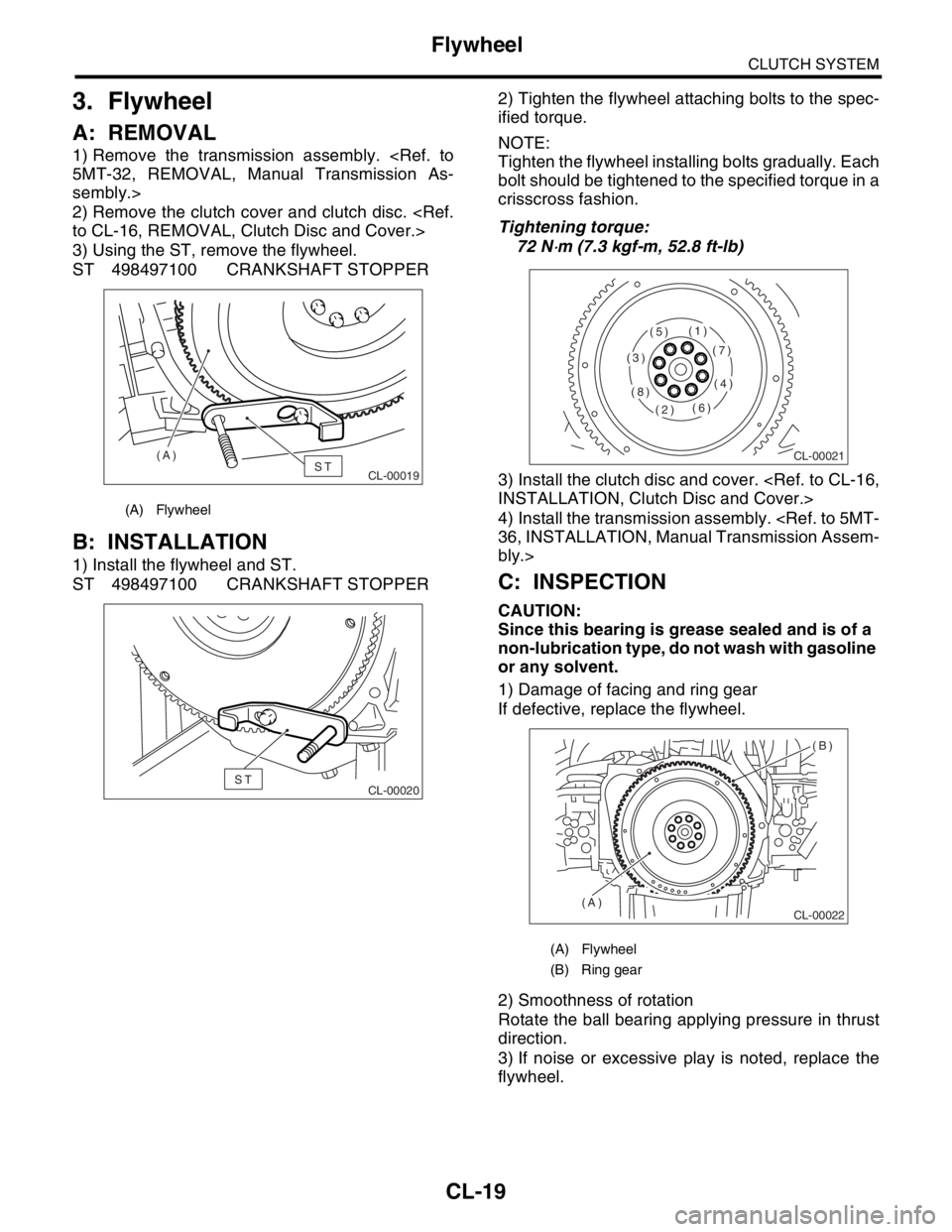
3) Using the ST, remove the flywheel.
ST 498497100 CRANKSHAFT STOPPER
B: INSTALLATION
1) Install the flywheel and ST.
ST 498497100 CRANKSHAFT STOPPER2) Tighten the flywheel attaching bolts to the spec-
ified torque.
NOTE:
Tighten the flywheel installing bolts gradually. Each
bolt should be tightened to the specified torque in a
crisscross fashion.
Tightening torque:
72 N
⋅m (7.3 kgf-m, 52.8 ft-lb)
3) Install the clutch disc and cover.
INSTALLATION, Clutch Disc and Cover.>
4) Install the transmission assembly.
36, INSTALLATION, Manual Transmission Assem-
bly.>
C: INSPECTION
CAUTION:
Since this bearing is grease sealed and is of a
non-lubrication type, do not wash with gasoline
or any solvent.
1) Damage of facing and ring gear
If defective, replace the flywheel.
2) Smoothness of rotation
Rotate the ball bearing applying pressure in thrust
direction.
3) If noise or excessive play is noted, replace the
flywheel.
(A) Flywheel
CL-00019ST (A)
CL-00020ST
(A) Flywheel
(B) Ring gear
CL-00021
(1)
(2)
(3)
(4)
(5)
(6)
(7)
(8)
CL-00022
(B)
(A)
Page:
< prev 1-8 9-16 17-24