2004 SUBARU FORESTER turn signal
[x] Cancel search: turn signalPage 390 of 2870

IDI-6
INSTRUMENTATION/DRIVER INFO
Combination Meter System
4. CHECK TRANSMISSION CONTROL MODULE (TCM)
3 CHECK HARNESS BETWEEN VEHICLE
SPEED SENSOR AND ENGINE GROUND.
1) Turn the ignition switch to OFF.
2) Measure the resistance between vehicle
speed sensor connector and engine ground.
Connector & terminal
(B17) No. 2 — Engine ground:Is the resistance less than 10
Ω?Go to step 4.Repair the wiring
harness.
4 CHECK HARNESS BETWEEN VEHICLE
SPEED SENSOR AND COMBINATION
METER.
1) Disconnect the connector from combination
meter.
2) Measure the resistance between vehicle
speed sensor harness connector and combi-
nation meter harness connector.
Connector & terminal
(B17) No. 1 — (i10) No. 12:Is the resistance less than 10
Ω?Replace the vehi-
cle speed sensor.Repair the wiring
harness.
Step Check Yes No
1 CHECK TCM SIGNAL.
1) Lift-up the vehicle and support it with rigid
racks.
2) Drive the vehicle faster than 10 km/h (6
MPH).
Warning:
Be careful not to get caught in the running
wheels.
3) Measure the voltage between TCM con-
nector and chassis ground.
Connector & terminal
(B56) No. 17 (+) — Chassis ground (
−):Is the voltage 1 V ← → 5 V? Go to step 2.Check TCM.
Basic Diagnostic
Procedure.>
2 CHECK HARNESS BETWEEN TCM AND
COMBINATION METER.
1) Turn the ignition switch to OFF.
2) Disconnect the connector from TCM and
combination meter.
3) Measure the resistance between TCM har-
ness connector and combination meter har-
ness connector.
Connector & terminal
(B56) No. 17 — (i10) No. 12:Is the resistance less than 10
Ω?Check the speedo
meter.
Speedometer.>Repair the wiring
harness. Step Check Yes No
Page 391 of 2870

IDI-7
INSTRUMENTATION/DRIVER INFO
Combination Meter System
5. CHECK ENGINE CONTROL MODULE (ECM)
6. CHECK FUEL LEVEL SENSOR
Step Check Yes No
1 CHECK ECM SIGNAL.
1) Start the engine.
2) Measure the voltage between ECM con-
nector and engine ground.
Connector & terminal
Non-turbo model
(B134) No. 10 (+) — Engine ground (
−):
Turbo model
(B134) No. 23 (+) — Engine ground (
−):Is the voltage 0 V ← → 14 V? Go to step 2.Check ECM.
Basic Diagnostics
Procedure.>
Basic Diagnostics
Procedure.>
2 CHECK HARNESS BETWEEN COMBINA-
TION METER AND ECM.
1) Turn the ignition switch to OFF.
2) Disconnect the connector from ECM and
combination meter.
3) Measure the resistance between ECM har-
ness connector and combination meter har-
ness connector.
Connector & terminal
Non-turbo model
(B134) No. 10 — (i10) No. 11:
Turbo model
(B134) No. 23 — (i10) No. 11:Is the resistance less than 10
Ω?Check the tachom-
eter.
Tachometer.>Repair the wiring
harness.
Step Check Yes No
1 CHECK FUEL LEVEL SENSOR.
1) Remove the fuel level sensor.
sor.>
2) Measure the resistance between fuel level
sensor terminals when setting the float to
FULL and EMPTY position.
Te r m i n a l s
No. 3 — No. 5:Is the resistance 0.5 to 2.5 Ω
(FULL) and 50 to 52 Ω
(EMPTY)?Go to step 2.Replace the fuel
level sensor.
2 CHECK FUEL SUB LEVEL SENSOR.
1) Remove the fuel sub level sensor.
Sensor.>
2) Measure the resistance between fuel sub
level sensor terminals when setting the float to
FULL and EMPTY position.
Te r m i n a l s
No. 1 — No. 2:Is the resistance 0.5 to 2.5 Ω
(FULL) and 42 to 44 Ω
(EMPTY)?Go to step 3.Replace the fuel
sub level sensor.
3 CHECK HARNESS BETWEEN FUEL SUB
LEVEL SENSOR AND COMBINATION
METER.
1) Disconnect the connector from combination
meter.
2) Measure the resistance between fuel sub
level sensor harness connector terminal and
combination meter harness connector termi-
nal.
Connector & terminal
(R59) No. 1 — (i11) No. 1:Is the resistance less than 10
Ω?Go to step 4.Repair the wiring
harness.
Page 396 of 2870

IDI-12
INSTRUMENTATION/DRIVER INFO
Combination Meter Assembly
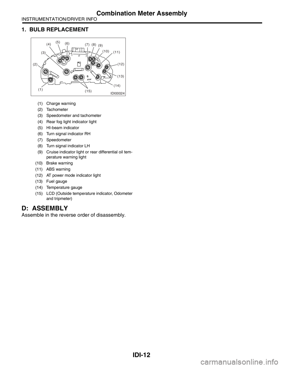
1. BULB REPLACEMENT
D: ASSEMBLY
Assemble in the reverse order of disassembly.
(1) Charge warning
(2) Tachometer
(3) Speedometer and tachometer
(4) Rear fog light indicator light
(5) HI-beam indicator
(6) Turn signal indicator RH
(7) Speedometer
(8) Turn signal indicator LH
(9) Cruise indicator light or rear differential oil tem-
perature warning light
(10) Brake warning
(11) ABS warning
(12) AT power mode indicator light
(13) Fuel gauge
(14) Temperature gauge
(15) LCD (Outside temperature indicator, Odometer
and tripmeter)
IDI00024(1) (2)(3)(5)
(6)
(7)(8)
(9)
(10)
(11)
(13)
(14)
(15)
(4)
(12)
Page 432 of 2870

SL-12
SECURITY AND LOCK
Door Lock Control System
5. CHECK DOOR LOCK ACTUATOR AND CIRCUIT
6. CHECK KEY CYLINDER LOCK SWITCH AND CIRCUIT
Step Check Yes No
1 CHECK OUTPUT SIGNAL.
Measure the voltage between the harness con-
nector terminal of keyless entry control module
or double lock module and chassis ground
when moving the door lock switch to LOCK.
Connector & terminal
Without double lock:
(B176) No. 18 (+) — Chassis ground (
−):
With double lock:
(B324) No. 3 (+) — Chassis ground (
−):Is the voltage more than 10 V? Go to step 2.Replace the key-
less entry control
module or double
lock module.
2 CHECK OUTPUT SIGNAL.
Measure the voltage between the harness con-
nector terminal of keyless entry control module
or double lock module and chassis ground
when moving the door lock switch to UNLOCK.
Connector & terminal
Without double lock:
(B176) No. 17 (+) — Chassis ground (
−):
With double lock:
(B324) No. 5 (+) — Chassis ground (
−):Is the voltage more than 10 V? Go to step 3.Replace the key-
less entry control
module or double
lock module.
3 CHECK DOOR LOCK ACTUATOR.
Check the door lock actuator.
Front door lock actuator:
Rear door lock actuator:
Rear gate latch lock actuator:
for open circuits or
shorts between
the keyless entry
control module or
double lock mod-
ule and the door
lock actuator.Replace the door
lock actuator.
Step Check Yes No
1 CHECK KEY CYLINDER LOCK SWITCH CIR-
CUIT.
1) Disconnect the double lock module har-
ness connector.
2) Measure the resistance between harness
connector terminal and chassis ground when
turning the key cylinder lock switch to lock
position.
Connector & terminal
(B325) No. 2 — Chassis ground:Is the resistance less than 10
Ω?Go to step 2.Go to step 3.
2 CHECK KEY CYLINDER LOCK SWITCH CIR-
CUIT.
Measure the resistance between harness con-
nector terminal and chassis ground when turn-
ing the key cylinder lock switch to unlock
position.
Connector & terminal
(B325) No. 3 — Chassis ground:Is the resistance less than 10
Ω?Key cylinder lock
switch is nor mal.Go to step 3.
Page 433 of 2870

SL-13
SECURITY AND LOCK
Door Lock Control System
7. CHECK DOOR LOCK ACTUATOR (DOUBLE LOCK) AND CIRCUIT
3 CHECK KEY CYLINDER LOCK SWITCH.
1) Disconnect the key cylinder lock switch
connector.
2) Measure the resistance between key cylin-
der lock switch terminals when turning the key
cylinder lock switch to lock position.
Te r m i n a l s
No. 1 — No. 2Is the resistance less than 1
Ω?Go to step 4.Replace the key
cylinder lock
switch.
4 CHECK KEY CYLINDER LOCK SWITCH.
Measure the resistance between key cylinder
lock switch terminals when turning the key cyl-
inder lock switch to unlock position.
Te r m i n a l s
No. 2 — No. 3Is the resistance less than 1
Ω?Check the harness
for open or short
circuits between
double lock mod-
ule and key cylin-
der lock switch.Replace the key
cylinder lock
switch.
Step Check Yes No
1 CHECK OUTPUT SIGNAL.
Measure the resistance between double lock
module harness connector terminal and chas-
sis ground when turning the key cylinder lock
switch to lock position.
Connector & terminal
(B324) No. 3 (+) — Chassis ground (
−):Is the voltage more than 10 V? Go to step 2.Replace the dou-
ble lock module.
2 CHECK OUTPUT SIGNAL.
Measure the resistance between double lock
module harness connector terminal and chas-
sis ground when turning the key cylinder lock
switch to unlock position.
Connector & terminal
(B324) No. 6 (+) — Chassis ground (
−):Is the voltage more than 10 V? Go to step 3.Replace the dou-
ble lock module.
3 CHECK DOOR LOCK ACTUATOR.
Check door lock actuator.
Front door lock actuator:
Rear door lock actuator:
mal?Check the harness
for open or short
circuits between
double lock mod-
ule and door lock
actuator.Replace the door
lock actuator. Step Check Yes No
Page 434 of 2870

SL-14
SECURITY AND LOCK
Keyless Entry System
3. Keyless Entry System
A: WIRING DIAGRAM
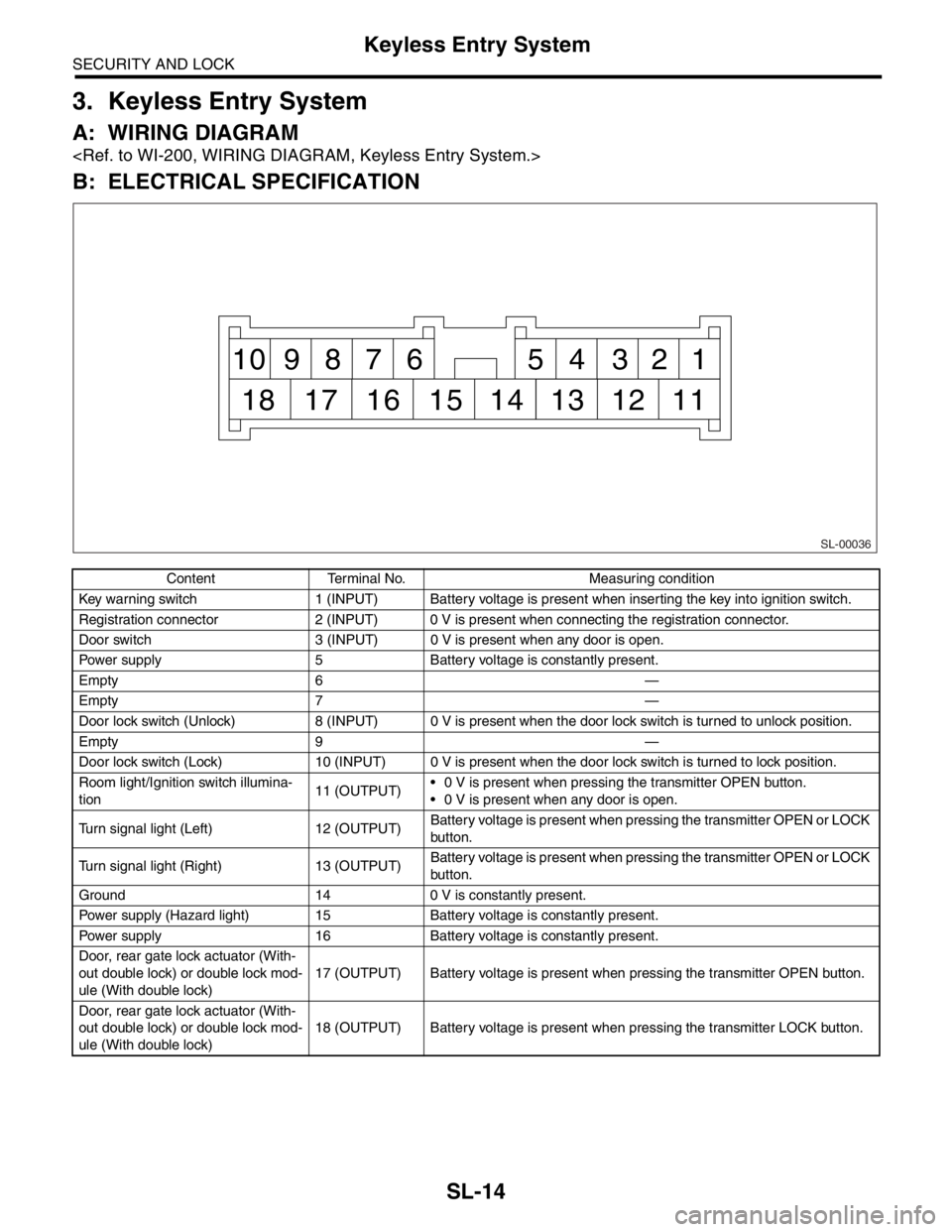
B: ELECTRICAL SPECIFICATION
Content Terminal No. Measuring condition
Key warning switch 1 (INPUT) Battery voltage is present when inserting the key into ignition switch.
Registration connector 2 (INPUT) 0 V is present when connecting the registration connector.
Door switch 3 (INPUT) 0 V is present when any door is open.
Power supply 5 Battery voltage is constantly present.
Empty 6 —
Empty 7 —
Door lock switch (Unlock) 8 (INPUT) 0 V is present when the door lock switch is turned to unlock position.
Empty 9 —
Door lock switch (Lock) 10 (INPUT) 0 V is present when the door lock switch is turned to lock position.
Room light/Ignition switch illumina-
tion11 (OUTPUT) 0 V is present when pressing the transmitter OPEN button.
0 V is present when any door is open.
Turn signal light (Left) 12 (OUTPUT)Battery voltage is present when pressing the transmitter OPEN or LOCK
button.
Turn signal light (Right) 13 (OUTPUT)Battery voltage is present when pressing the transmitter OPEN or LOCK
button.
Ground 14 0 V is constantly present.
Power supply (Hazard light) 15 Battery voltage is constantly present.
Power supply 16 Battery voltage is constantly present.
Door, rear gate lock actuator (With-
out double lock) or double lock mod-
ule (With double lock)17 (OUTPUT) Battery voltage is present when pressing the transmitter OPEN button.
Door, rear gate lock actuator (With-
out double lock) or double lock mod-
ule (With double lock)18 (OUTPUT) Battery voltage is present when pressing the transmitter LOCK button.
SL-00036
1 2 3 4 5 6 7 8 9 10
11 12 13 14 15 16 17 18
Page 440 of 2870

SL-20
SECURITY AND LOCK
Keyless Entry System
8. CHECK HAZARD LIGHT OPERATION
9. CHECK ROOM LIGHT OPERATION
Step Check Yes No
1 CHECK HAZARD LIGHT OPERATION.
Make sure the hazard light blinks when hazard
switch is turned ON.Does the hazard light blink? Go to step 2.Check the hazard
light circuit.
2 CHECK OUTPUT SIGNAL.
1) Remove the key from ignition switch.
2) Close all doors and rear gate.
3) Measure the voltage between keyless entry
control module harness connector terminal
and chassis ground when LOCK or OPEN but-
ton of transmitter is pressed.
Connector & terminal
(B176) No. 12, No. 13 (+) — Chassis
ground (
−):Is the voltage more than 10 V? Check the harness
for open or short
between keyless
entry control mod-
ule and turn signal
lights.Replace the key-
less entry control
module.
Step Check Yes No
1 CHECK ROOM LIGHT OPERATION.
Make sure the room light illuminates when the
room light switch is turned ON.Does the room light illuminate? Go to step 2.Check the room
light circuit.
2 CHECK HARNESS BETWEEN ROOM LIGHT
AND KEYLESS ENTRY CONTROL MODULE
(WITHOUT DOUBLE LOCK) OR DOUBLE
LOCK MODULE (WITH DOUBLE LOCK).
1) Disconnect the keyless entry control mod-
ule or double lock module harness connector
and room light harness connector.
2) Measure the resistance between keyless
entry control module or double lock module
harness connector terminal and room light har-
ness connector terminal.
Connector & terminal
Without double lock:
(B176) No. 11 — (R52) No. 2:
With double lock:
(B325) No. 1 — (R52) No. 2:Is the resistance less than 10
Ω?The room light
operation circuit is
OK.Check the harness
for open circuits or
shorts between
keyless entry con-
trol module (With-
out double lock) or
double lock mod-
ule (With double
lock) and room
light.
Page 575 of 2870

CC(H4SO)-7
CRUISE CONTROL SYSTEM (DIAGNOSTIC)
Cruise Control Module I/O Signal
4. Cruise Control Module I/O Signal
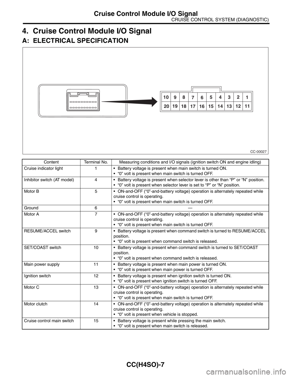
A: ELECTRICAL SPECIFICATION
Content Terminal No. Measuring conditions and I/O signals (ignition switch ON and engine idling)
Cruise indicator light 1 Battery voltage is present when main switch is turned ON.
“0” volt is present when main switch is turned OFF.
Inhibitor switch (AT model) 4 Battery voltage is present when selector lever is other than “P” or “N” position.
“0” volt is present when selector lever is set to “P” or “N” position.
Motor B 5 ON-and-OFF (“0”-and-battery voltage) operation is alternately repeated while
cruise control is operating.
“0” volt is present when main switch is turned OFF.
Ground 6 —
Motor A 7 ON-and-OFF (“0”-and-battery voltage) operation is alternately repeated while
cruise control is operating.
“0” volt is present when main switch is turned OFF.
RESUME/ACCEL switch 9 Battery voltage is present when command switch is turned to RESUME/ACCEL
position.
“0” volt is present when command switch is released.
SET/COAST switch 10 Battery voltage is present when command switch is turned to SET/COAST
position.
“0” volt is present when command switch is released.
Main power supply 11 Battery voltage is present when main power is turned ON.
“0” volt is present when main power is turned OFF.
Ignition switch 12 Battery voltage is present when ignition switch is turned ON.
“0” volt is present when ignition switch is turned OFF.
Motor C 13 ON-and-OFF (“0”-and-battery voltage) operation is alternately repeated while
cruise control is operating.
“0” volt is present when main switch is turned OFF.
Motor clutch 14 ON-and-OFF (“0”-and-battery voltage) operation is alternately repeated while
cruise control is operating.
“0” volt is present when vehicle is stopped.
Cruise control main switch 15 Battery voltage is present while pressing the main switch.
“0” volt is present when main switch is released.
CC-00027
10
98
765432
1
2019
18
17 1615 14 1312 11