2004 SUBARU FORESTER brake fluid
[x] Cancel search: brake fluidPage 771 of 2870
PM-34
PERIODIC MAINTENANCE SERVICE
Brake Linings and Drums
21.Brake Linings and Drums
A: INSPECTION
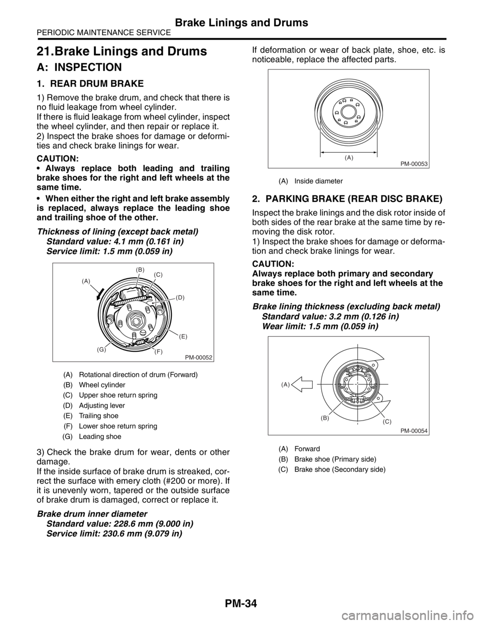
1. REAR DRUM BRAKE
1) Remove the brake drum, and check that there is
no fluid leakage from wheel cylinder.
If there is fluid leakage from wheel cylinder, inspect
the wheel cylinder, and then repair or replace it.
2) Inspect the brake shoes for damage or deformi-
ties and check brake linings for wear.
CAUTION:
Always replace both leading and trailing
brake shoes for the right and left wheels at the
same time.
When either the right and left brake assembly
is replaced, always replace the leading shoe
and trailing shoe of the other.
Thickness of lining (except back metal)
Standard value: 4.1 mm (0.161 in)
Service limit: 1.5 mm (0.059 in)
3) Check the brake drum for wear, dents or other
damage.
If the inside surface of brake drum is streaked, cor-
rect the surface with emery cloth (#200 or more). If
it is unevenly worn, tapered or the outside surface
of brake drum is damaged, correct or replace it.
Brake drum inner diameter
Standard value: 228.6 mm (9.000 in)
Service limit: 230.6 mm (9.079 in)If deformation or wear of back plate, shoe, etc. is
noticeable, replace the affected parts.
2. PARKING BRAKE (REAR DISC BRAKE)
Inspect the brake linings and the disk rotor inside of
both sides of the rear brake at the same time by re-
moving the disk rotor.
1) Inspect the brake shoes for damage or deforma-
tion and check brake linings for wear.
CAUTION:
Always replace both primary and secondary
brake shoes for the right and left wheels at the
same time.
Brake lining thickness (excluding back metal)
Standard value: 3.2 mm (0.126 in)
Wear limit: 1.5 mm (0.059 in)
(A) Rotational direction of drum (Forward)
(B) Wheel cylinder
(C) Upper shoe return spring
(D) Adjusting lever
(E) Trailing shoe
(F) Lower shoe return spring
(G) Leading shoe
PM-00052
(B)
(C)
(D)
(E)
(F) (G) (A)
(A) Inside diameter
(A) Forward
(B) Brake shoe (Primary side)
(C) Brake shoe (Secondary side)
PM-00053(A)
PM-00054
(B)
(C) (A)
Page 909 of 2870
ME(H4SO)-40
MECHANICAL
Engine Assembly
11) Tighten the nuts which hold lower side of trans-
mission to engine.
Tightening torque:
50 N
⋅m (5.1 kgf-m, 36.9 ft-lb)
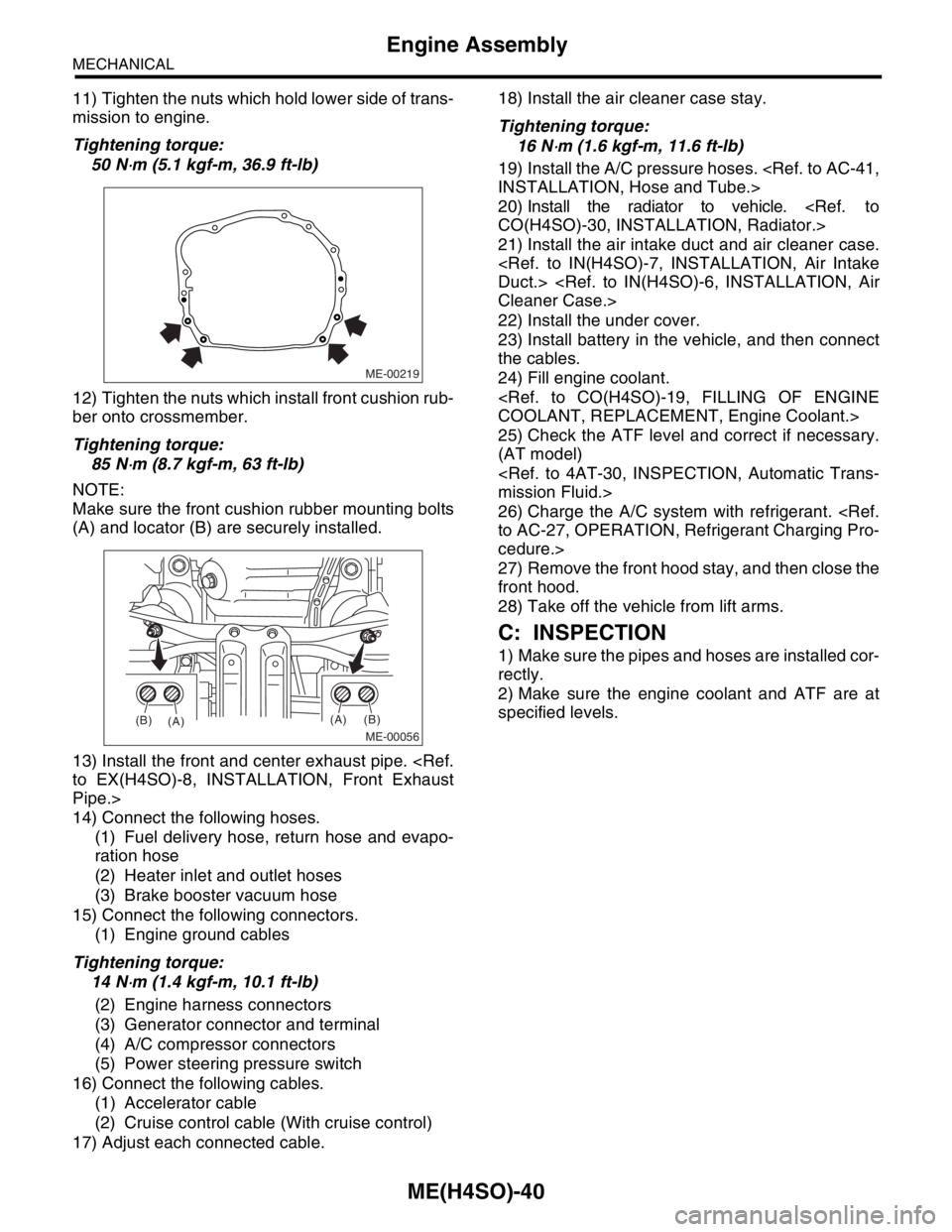
12) Tighten the nuts which install front cushion rub-
ber onto crossmember.
Tightening torque:
85 N
⋅m (8.7 kgf-m, 63 ft-lb)
NOTE:
Make sure the front cushion rubber mounting bolts
(A) and locator (B) are securely installed.
13) Install the front and center exhaust pipe.
Pipe.>
14) Connect the following hoses.
(1) Fuel delivery hose, return hose and evapo-
ration hose
(2) Heater inlet and outlet hoses
(3) Brake booster vacuum hose
15) Connect the following connectors.
(1) Engine ground cables
Tightening torque:
14 N
⋅m (1.4 kgf-m, 10.1 ft-lb)
(2) Engine harness connectors
(3) Generator connector and terminal
(4) A/C compressor connectors
(5) Power steering pressure switch
16) Connect the following cables.
(1) Accelerator cable
(2) Cruise control cable (With cruise control)
17) Adjust each connected cable.18) Install the air cleaner case stay.
Tightening torque:
16 N
⋅m (1.6 kgf-m, 11.6 ft-lb)
19) Install the A/C pressure hoses.
20) Install the radiator to vehicle.
21) Install the air intake duct and air cleaner case.
22) Install the under cover.
23) Install battery in the vehicle, and then connect
the cables.
24) Fill engine coolant.
25) Check the ATF level and correct if necessary.
(AT model)
26) Charge the A/C system with refrigerant.
cedure.>
27) Remove the front hood stay, and then close the
front hood.
28) Take off the vehicle from lift arms.
C: INSPECTION
1) Make sure the pipes and hoses are installed cor-
rectly.
2) Make sure the engine coolant and ATF are at
specified levels.
ME-00219
ME-00056
(A)
(A)(B)
(B)
Page 1135 of 2870

EN(H4SO)-37
ENGINE (DIAGNOSTIC)
Inspection Mode
12.Inspection Mode
A: OPERATION
Perform the diagnosis on the “Diagnosis Trouble Codes (DTC) List” below.
Refer to the item of drive cycle when perform the diagnosis not on the “Diagnosis Trouble Codes (DTC) List”
below.
DTC Item
P0030 HO2S Heater Control Circuit (Bank 1 Sensor 1)
P0031 HO2S Heater Control Circuit Low (Bank 1 Sensor 1)
P0032 HO2S Heater Control Circuit High (Bank 1 Sensor 1)
P0037 HO2S Heater Control Circuit Low (Bank 1 Sensor 2)
P0038 HO2S Heater Control Circuit High (Bank 1 Sensor 2)
P0068 Manifold Pressure Sensor Range/Performance
P0107 Manifold Absolute Pressure/Barometric Pressure Circuit Low Input
P0108 Manifold Absolute Pressure/Barometric Pressure Circuit High Input
P0112 Intake Air Temperature Circuit Low Input
P0113 Intake Air Temperature Circuit High Input
P0117 Engine Coolant Temperature Circuit Low Input
P0118 Engine Coolant Temperature Circuit High Input
P0122 Throttle/Pedal Position Sensor/Switch “A” Circuit Low Input
P0123 Throttle/Pedal Position Sensor/Switch “A” Circuit High Input
P0129 Barometric Pressure Too Low
P0131 O
2 Sensor Circuit Low Voltage (Bank 1 Sensor 1)
P0132 O
2 Sensor Circuit High Voltage (Bank 1 Sensor 1)
P0134 O
2 Sensor Circuit No Activity Detected (Bank 1 Sensor 1)
P0137 O
2 Sensor Circuit Low Voltage (Bank 1 Sensor 2)
P0138 O
2 Sensor Circuit High Voltage (Bank 1 Sensor 2)
P0327 Knock Sensor 1 Circuit Low Input (Bank 1 or Single Sensor)
P0328 Knock Sensor 1 Circuit High Input (Bank 1 or Single Sensor)
P0335 Crankshaft Position Sensor “A” Circuit
P0336 Crankshaft Position Sensor “A” Circuit Range/Performance
P0340 Camshaft Position Sensor “A” Circuit (Bank 1 or Single Sensor)
P0341 Camshaft Position Sensor “A” Circuit Range/Performance (Bank 1 or Single Sensor)
P0458 Evaporative Emission Control System Purge Control Valve Circuit Low
P0462 Fuel Level Sensor Circuit Low Input
P0463 Fuel Level Sensor Circuit High Input
P0502 Vehicle Speed Sensor Circuit Low Input
P0503 Vehicle Speed Sensor Intermittent/Erratic/High
P0512 Starter Request Circuit
P0513 Incorrect Immobilizer Key
P0519 Idle Control System Malfunction (Fail-Safe)
P0565 Cruise Control On Signal
P0604 Internal Control Module Random Access Memory (RAM) Error
P0703 Torque Converter/Brake Switch “B” Circuit
P0705 Transmission Range Sensor Circuit (PRNDL Input)
P0710 Transmission Fluid Temperature Sensor Circuit
P0716 Torque converter turbine speed sensor
P0720 AT Vehicle Speed Sensor Circuit Malfunction
P0726 Engine Speed Input Circuit Malfunction
P0731 Gear 1 Incorrect Ratio
P0732 Gear 2 Incorrect Ratio
P0733 Gear 3 Incorrect Ratio
Page 1172 of 2870

EN(H4SO)-74
ENGINE (DIAGNOSTIC)
List of Diagnostic Trouble Code (DTC)
P0420 Catalyst System Efficiency Below
Threshold (Bank 1)
Trouble Code (DTC).>
P0458 Evaporative Emission Control Sys-
tem Purge Control Valve Circuit Low
cedure with Diagnostic Trouble Code (DTC).>
P0459 Evaporative Emission Control Sys-
tem Purge Control Valve Circuit High
Procedure with Diagnostic Trouble Code (DTC).>
P0461 Fuel Level Sensor Circuit Range/Per-
formance
Code (DTC).>
P0462 Fuel Level Sensor Circuit Low Input
P0463 Fuel Level Sensor Circuit High Input
P0464 Fuel Level Sensor Circuit Intermittent
(DTC).>
P0483 Cooling Fan Rationality Check
P0502 Vehicle Speed Sensor Circuit Low
Input
P0503 Vehicle Speed Sensor Intermittent/
Erratic/High
P0506 Idle Control System RPM Lower
Than Expected
Code (DTC).>
P0507 Idle Control System RPM Higher
Than Expected
Code (DTC).>
P0512 Starter Request Circuit
P0513 Incorrect Immobilizer Key
P0519 Idle Control System Malfunction
(Fail-Safe)
(DTC).>
P0565 Cruise Control On Signal
P0604 Internal Control Module Random
Access Memory (RAM) Error
nostic Trouble Code (DTC).>
P0691 Cooling Fan 1 Control Circuit Low
P0692 Cooling Fan 1 Control Circuit High
P0703 Torque Converter/Brake Switch “B”
Circuit
(DTC).>
P0705 Transmission Range Sensor Circuit
(PRNDL Input)
P0710 Transmission Fluid Temperature
Sensor Circuit
P0716 Torque converter turbine speed sen-
sor
Page 2321 of 2870
4AT-9
AUTOMATIC TRANSMISSION
General Description
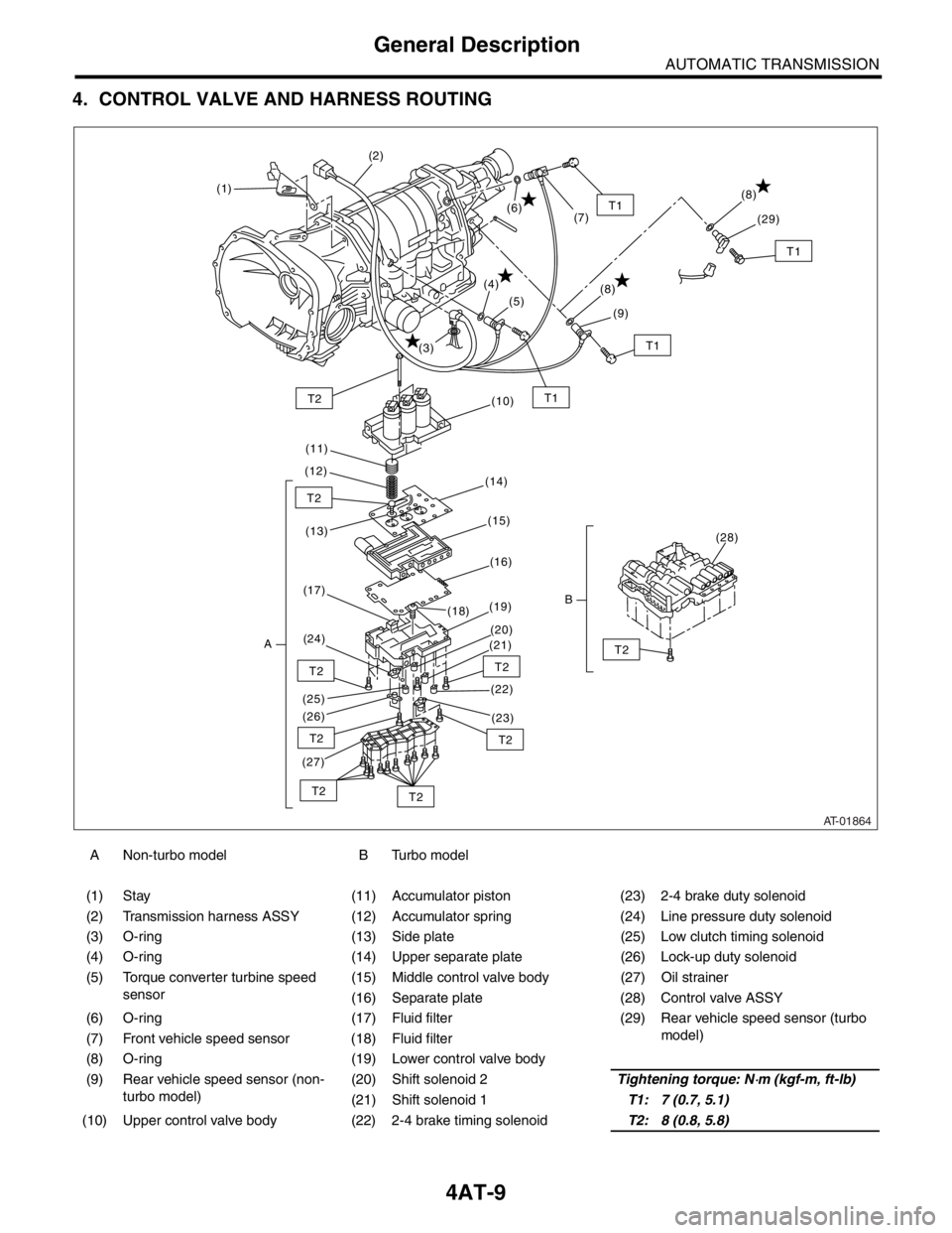
4. CONTROL VALVE AND HARNESS ROUTING
A Non-turbo model B Turbo model
(1) Stay (11) Accumulator piston (23) 2-4 brake duty solenoid
(2) Transmission harness ASSY (12) Accumulator spring (24) Line pressure duty solenoid
(3) O-ring (13) Side plate (25) Low clutch timing solenoid
(4) O-ring (14) Upper separate plate (26) Lock-up duty solenoid
(5) Torque converter turbine speed
sensor(15) Middle control valve body (27) Oil strainer
(16) Separate plate (28) Control valve ASSY
(6) O-ring (17) Fluid filter (29) Rear vehicle speed sensor (turbo
model)
(7) Front vehicle speed sensor (18) Fluid filter
(8) O-ring (19) Lower control valve body
(9) Rear vehicle speed sensor (non-
turbo model)(20) Shift solenoid 2Tightening torque: N
⋅m (kgf-m, ft-lb)
(21) Shift solenoid 1T1: 7 (0.7, 5.1)
(10) Upper control valve body (22) 2-4 brake timing solenoidT2: 8 (0.8, 5.8)
AT-01864
T1T2
T2
T2
T2
T2
T2
T2T2
T2
T1
(1)(2)
(3)(4)
(5)
(6)
(7)
(10)
(11)
(12)
(14)
(13)(15)
(16)
(17)
A(24)(19)
(18)
(20)
(21)
(22)
(23) (26) (25)
(27)
(28)
B
T1
(8)
(9)
T1
(8)
(29)
Page 2347 of 2870

4AT-35
AUTOMATIC TRANSMISSION
Time Lag Test
6. Time Lag Test
A: INSPECTION
NOTE:
If the select lever is shifted while the engine is
idling, there will be a certain time elapse or lag be-
fore the shock can be felt. This is used for checking
the condition of the low clutch, reverse clutch, low &
reverse brake and one-way clutch.
Perform the test at normal operation fluid tem-
perature 70 — 80°C (158 — 176°F).
Be sure to allow a one minute interval between
tests.
Perform measurement for three times and take
the average value.
1) Fully apply the parking brake.
2) Start the engine.
Check the idling speed (A/C OFF).
3) Shift the select lever from “N” to “D” range.
Using a stop watch, measure the time it takes from
shifting the lever until the shock is felt.
Time lag: Less than 1.2 seconds
If “N” → “D” time lag is longer than specified:
Line pressure too low
Low clutch worn
One-way clutch not operating properly
D-ring worn
4) In the same manner, measure the time lag for
“N” → “R”.
Time lag: Less than 1.5 seconds
If “N” → “R” time lag is longer than specified:
Line pressure too low
Reverse clutch worn
Low & reverse brake worn
D-ring worn
Page 2378 of 2870
4AT-65
AUTOMATIC TRANSMISSION
Control Valve Body
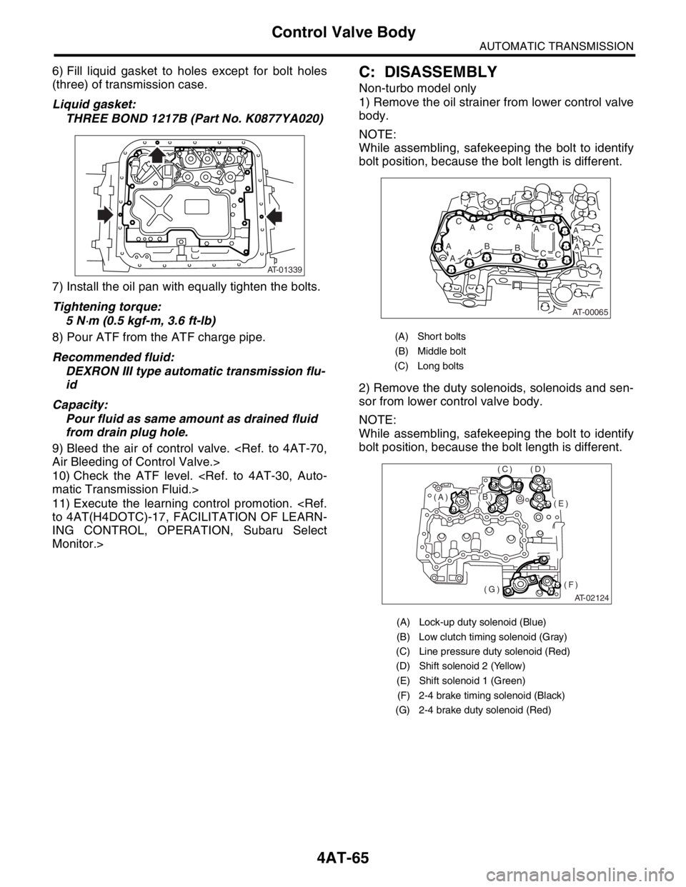
6) Fill liquid gasket to holes except for bolt holes
(three) of transmission case.
Liquid gasket:
THREE BOND 1217B (Part No. K0877YA020)
7) Install the oil pan with equally tighten the bolts.
Tightening torque:
5 N
⋅m (0.5 kgf-m, 3.6 ft-lb)
8) Pour ATF from the ATF charge pipe.
Recommended fluid:
DEXRON III type automatic transmission flu-
id
Capacity:
Pour fluid as same amount as drained fluid
from drain plug hole.
9) Bleed the air of control valve.
10) Check the ATF level.
11) Execute the learning control promotion.
ING CONTROL, OPERATION, Subaru Select
Monitor.>
C: DISASSEMBLY
Non-turbo model only
1) Remove the oil strainer from lower control valve
body.
NOTE:
While assembling, safekeeping the bolt to identify
bolt position, because the bolt length is different.
2) Remove the duty solenoids, solenoids and sen-
sor from lower control valve body.
NOTE:
While assembling, safekeeping the bolt to identify
bolt position, because the bolt length is different.
AT-01339
(A) Short bolts
(B) Middle bolt
(C) Long bolts
(A) Lock-up duty solenoid (Blue)
(B) Low clutch timing solenoid (Gray)
(C) Line pressure duty solenoid (Red)
(D) Shift solenoid 2 (Yellow)
(E) Shift solenoid 1 (Green)
(F) 2-4 brake timing solenoid (Black)
(G) 2-4 brake duty solenoid (Red)
AT-00065
A
ABAA
AC
ACC
AB
AC
CC
AT-02124
(E)
(F)(G)
(D)(C)
(B)(A)
Page 2385 of 2870
4AT-72
AUTOMATIC TRANSMISSION
Shift Solenoids, Duty Solenoids and ATF Temperature Sensor
2) Tighten the bolt and nut.
Tightening torque:
8 N
⋅m (0.8 kgf-m, 5.8 ft-lb)
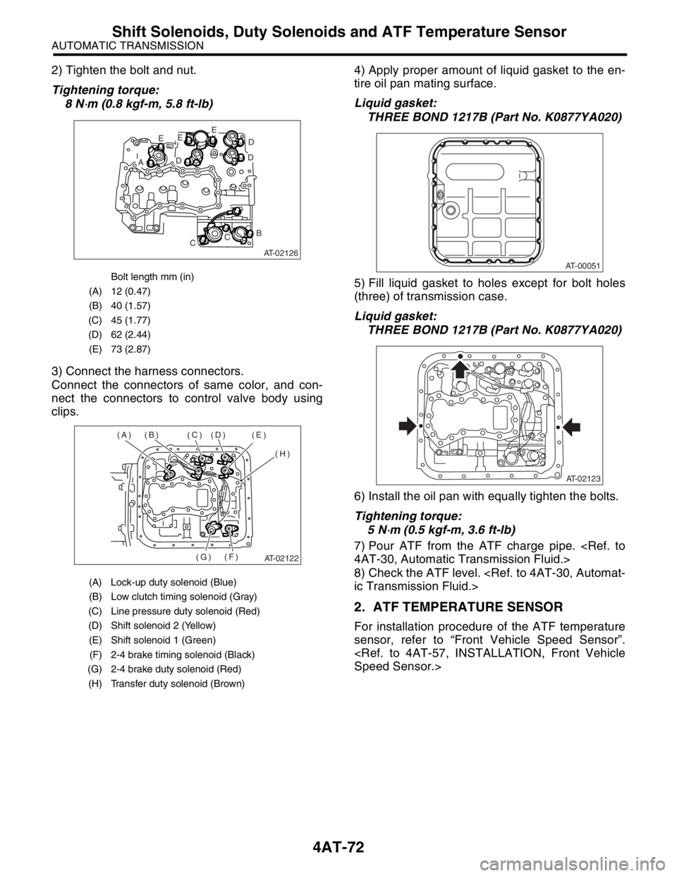
3) Connect the harness connectors.
Connect the connectors of same color, and con-
nect the connectors to control valve body using
clips.4) Apply proper amount of liquid gasket to the en-
tire oil pan mating surface.
Liquid gasket:
THREE BOND 1217B (Part No. K0877YA020)
5) Fill liquid gasket to holes except for bolt holes
(three) of transmission case.
Liquid gasket:
THREE BOND 1217B (Part No. K0877YA020)
6) Install the oil pan with equally tighten the bolts.
Tightening torque:
5 N
⋅m (0.5 kgf-m, 3.6 ft-lb)
7) Pour ATF from the ATF charge pipe.
8) Check the ATF level.
2. ATF TEMPERATURE SENSOR
For installation procedure of the ATF temperature
sensor, refer to “Front Vehicle Speed Sensor”.
Bolt length mm (in)
(A) 12 (0.47)
(B) 40 (1.57)
(C) 45 (1.77)
(D) 62 (2.44)
(E) 73 (2.87)
(A) Lock-up duty solenoid (Blue)
(B) Low clutch timing solenoid (Gray)
(C) Line pressure duty solenoid (Red)
(D) Shift solenoid 2 (Yellow)
(E) Shift solenoid 1 (Green)
(F) 2-4 brake timing solenoid (Black)
(G) 2-4 brake duty solenoid (Red)
(H) Transfer duty solenoid (Brown)
AT-02126
E
AD
EE
D
D
B
CC
AT-02122
(A) (B) (C) (D) (E)
(H)
(F)
(G)
AT-00051
AT-02123