2004 SUBARU FORESTER brake fluid
[x] Cancel search: brake fluidPage 2477 of 2870
![SUBARU FORESTER 2004 Service Repair Manual 4AT(H4SO)-18
AUTOMATIC TRANSMISSION (DIAGNOSTIC)
Subaru Select Monitor
2. READ CURRENT DATA
1) On the «Main Menu» display screen, select the {Each System Check} and press the [YES] key.
2) On the « SUBARU FORESTER 2004 Service Repair Manual 4AT(H4SO)-18
AUTOMATIC TRANSMISSION (DIAGNOSTIC)
Subaru Select Monitor
2. READ CURRENT DATA
1) On the «Main Menu» display screen, select the {Each System Check} and press the [YES] key.
2) On the «](/manual-img/17/57426/w960_57426-2476.png)
4AT(H4SO)-18
AUTOMATIC TRANSMISSION (DIAGNOSTIC)
Subaru Select Monitor
2. READ CURRENT DATA
1) On the «Main Menu» display screen, select the {Each System Check} and press the [YES] key.
2) On the «System Selection Menu» display screen, select the {Transmission Control System} and press the
[YES] key.
3) Press the [YES] key after the information of transmission type is displayed.
4) On the «Transmission Diagnosis» display screen, select the {Current Data Display & Save} and press the
[YES] key.
5) On the «Data Display Menu» display screen, select the {Data Display} and press the [YES] key.
6) Using the scroll key, move the display screen up or down until desired data is shown.
A list of the support data is shown in the following table.
NOTE:
For detailed operation procedure, refer to the SUBARU SELECT MONITOR OPERATION MANUAL.
Contents Display Unit of measure
Battery voltage Battery Voltage V
Rear vehicle speed sensor signal Rear Wheel Speed km/h or MPH
Front vehicle speed sensor signal Front Wheel Speed km/h or MPH
Engine speed signal Engine Speed rpm
Automatic transmission fluid temperature signal ATF Temp.°C or °F
Throttle position signal Throttle Sensor Voltage V
Gear position Gear Position —
Line pressure control duty ratio Line Pressure Duty Ratio %
Lock up clutch control duty ratio Lock Up Duty Ratio %
Transfer clutch control duty ratio (AWD model) Transfer Duty Ratio %
Power supply for throttle position sensor Throttle Sensor Power V
Torque converter turbine speed signal Turbine Revolution Speed rpm
2-4 brake timing pressure control duty ratio Brake Clutch Duty Ratio %
Intake manifold pressure sensor voltage Mani. Pressure Voltage V
FWD switch signal FWD Switch ON or OFF
Stop light switch signal Stop Light Switch ON or OFF
Anti lock brake system signal ABS Signal ON or OFF
Cruise control system signal Cruise Control Signal ON or OFF
Parking range signal P Range Signal ON or OFF
Neutral range signal N Range Signal ON or OFF
Reverse range signal R Range Signal ON or OFF
Drive range signal D Range Signal ON or OFF
3rd range signal 3rd Range Signal ON or OFF
2nd range signal 2nd Range Signal ON or OFF
1st range signal 1st Range Signal ON or OFF
Shift control solenoid A Shift Solenoid #1 ON or OFF
Shift control solenoid B Shift Solenoid #2 ON or OFF
Torque control output signal #1 Torque Control Signal 1 ON or OFF
Torque control output signal #2 Torque Control Signal 2 ON or OFF
Torque control cut signal Torque Control Cut Sig. ON or OFF
2-4 brake timing control solenoid valve 2-4 Brake Timing Sol. ON or OFF
Low clutch timing control solenoid valve Low Clutch Timing Sol. ON or OFF
Automatic transmission diagnosis indicator lamp Diagnosis Lamp ON or OFF
Power mode switch signal Power Mode Switch ON or OFF
Hold mode switch signal Hold Mode Switch ON or OFF
Kick down switch signal Kick Down Switch ON or OFF
Automatic transmission fluid temperature lamp ATF Temperature Lamp ON or OFF
Page 2592 of 2870

4AT(H4DOTC)-16
AUTOMATIC TRANSMISSION (DIAGNOSTIC)
Subaru Select Monitor
6) Using the scroll key, move the display screen up or down until desired data is shown.
A list of the support data is shown in the following table.
NOTE:
For detailed operation procedure, refer to the “SUBARU SELECT MONITOR OPERATION MANUAL”.
Contents Display Unit of measure
Battery voltage Battery Voltage V
Rear vehicle speed sensor signal Rear Wheel Speed km/h or MPH
Front vehicle speed sensor signal Front Wheel Speed km/h or MPH
Engine speed signal Engine Speed rpm
ATF temperature signal ATF Temp.°C or °F
Throttle position signal Throttle Sensor Voltage V
Gear position Gear Position —
Line pressure control duty ratio Line Pressure Duty Ratio %
Lock up clutch control duty ratio Lock Up Duty Ratio %
Transfer clutch control duty ratio Transfer Duty Ratio %
Power supply for throttle position sensor Throttle Sensor Power V
Torque converter turbine speed signal Turbine Revolution Speed rpm
2-4 brake timing pressure control duty ratio Brake Clutch Duty Ratio %
Low clutch duty ratio L/C Duty %
High clutch duty ratio H/C Duty %
Low & reverse brake duty ratio L&R/B Duty %
Throttle position Throttle position %
Accelerator pedal position Accel. Opening Angle %
Cruise control system Cruise Control Signal ON or OFF
Automatic transmission fluid temperature lamp ATF Temperature Lamp ON or OFF
Stop light switch signal Stop Light Switch ON or OFF
ABS signal ABS Signal ON or OFF
Parking range signal P Range Signal ON or OFF
Neutral range signal N Range Signal ON or OFF
Reverse range signal R Range Signal ON or OFF
Drive range signal D Range Signal ON or OFF
3rd range signal 3rd Range Signal ON or OFF
2nd range signal 2nd Range Signal ON or OFF
1st range signal 1st Range Signal ON or OFF
AT diagnosis indicator lamp Diagnosis Lamp ON or OFF
POWER switch signal POWER Switch ON or OFF
HOLD switch signal HOLD Switch ON or OFF
FWD switch signal FWD SW ON or OFF
Shift lock solenoid signal Shift Lock solenoid ON or OFF
Page 2606 of 2870

4AT(H4DOTC)-30
AUTOMATIC TRANSMISSION (DIAGNOSTIC)
List of Diagnostic Trouble Code (DTC)
12.List of Diagnostic Trouble Code (DTC)
A: LIST
DTC Item Diagnosis content Reference
P0705Transmission Range Sen-
sor Circuit (PRNDL Input)Inhibitor switch malfunction, open or
short circuit
Diagnostic Procedure with Diagnostic
Trouble Code (DTC).>
P0712Transmission Fluid Temper-
ature Sensor Circuit Low
InputATF temperature sensor malfunction,
open input signal circuit
TURE SENSOR CIRCUIT LOW INPUT,
Diagnostic Procedure with Diagnostic
Trouble Code (DTC).>
P0713Transmission Fluid Temper-
ature Sensor Circuit High
InputATF temperature sensor malfunction,
short input signal circuit
TURE SENSOR CIRCUIT HIGH INPUT,
Diagnostic Procedure with Diagnostic
Trouble Code (DTC).>
P0715Input/Turbine Speed Sensor
CircuitTorque converter turbine speed sen-
sor malfunction, open or short input
signal circuit
CIRCUIT, Diagnostic Procedure with
Diagnostic Trouble Code (DTC).>
P0719Torque Converter/Brake
Switch “B” Circuit Low Brake switch malfunction, open input
signal circuit
SWITCH “B” CIRCUIT LOW, Diagnostic
Procedure with Diagnostic Trouble Code
(DTC).>
P0720Output Speed Sensor Cir-
cuitFront vehicle speed sensor malfunc-
tion, open or short input signal circuit
Diagnostic Procedure with Diagnostic
Trouble Code (DTC).>
P0724Torque Converter/Brake
Switch “B” Circuit HighBrake switch malfunction, short input
signal circuit
SWITCH “B” CIRCUIT HIGH, Diagnostic
Procedure with Diagnostic Trouble Code
(DTC).>
P0725 Engine Speed Input CircuitOpen or short engine speed output
signal circuit
nostic Procedure with Diagnostic Trouble
Code (DTC).>
P0731 Gear 1 Incorrect Ratio Vehicle speed sensor, torque con-
verter turbine speed sensor, or con-
trol valve malfunction
tic Procedure with Diagnostic Trouble
Code (DTC).>
P0732 Gear 2 Incorrect Ratio Vehicle speed sensor, torque con-
verter turbine speed sensor, or con-
trol valve malfunction
tic Procedure with Diagnostic Trouble
Code (DTC).>
P0733 Gear 3 Incorrect Ratio Vehicle speed sensor, torque con-
verter turbine speed sensor, or con-
trol valve malfunction
tic Procedure with Diagnostic Trouble
Code (DTC).>
P0734 Gear 4 Incorrect Ratio Vehicle speed sensor, torque con-
verter turbine speed sensor, or con-
trol valve malfunction
tic Procedure with Diagnostic Trouble
Code (DTC).>
Page 2852 of 2870

CL-26
CLUTCH SYSTEM
Master Cylinder
6. Master Cylinder
A: REMOVAL
1) Thoroughly drain the brake fluid from reservoir
tank.
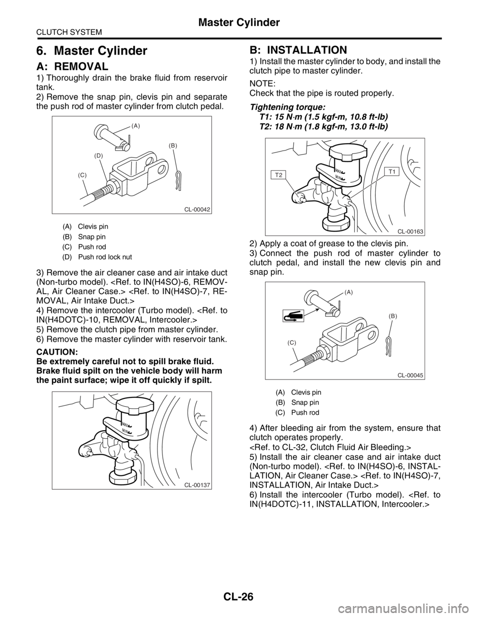
2) Remove the snap pin, clevis pin and separate
the push rod of master cylinder from clutch pedal.
3) Remove the air cleaner case and air intake duct
(Non-turbo model).
4) Remove the intercooler (Turbo model).
5) Remove the clutch pipe from master cylinder.
6) Remove the master cylinder with reservoir tank.
CAUTION:
Be extremely careful not to spill brake fluid.
Brake fluid spilt on the vehicle body will harm
the paint surface; wipe it off quickly if spilt.
B: INSTALLATION
1) Install the master cylinder to body, and install the
clutch pipe to master cylinder.
NOTE:
Check that the pipe is routed properly.
Tightening torque:
T1: 15 N
⋅m (1.5 kgf-m, 10.8 ft-lb)
T2: 18 N
⋅m (1.8 kgf-m, 13.0 ft-lb)
2) Apply a coat of grease to the clevis pin.
3) Connect the push rod of master cylinder to
clutch pedal, and install the new clevis pin and
snap pin.
4) After bleeding air from the system, ensure that
clutch operates properly.
5) Install the air cleaner case and air intake duct
(Non-turbo model).
6) Install the intercooler (Turbo model).
(A) Clevis pin
(B) Snap pin
(C) Push rod
(D) Push rod lock nut
CL-00042
(A)
(B)
(C)(D)
CL-00137
(A) Clevis pin
(B) Snap pin
(C) Push rod
CL-00163
T2T1
CL-00045
(A)
(B)
(C)
Page 2857 of 2870

CL-31
CLUTCH SYSTEM
Clutch Fluid
8. Clutch Fluid
A: INSPECTION
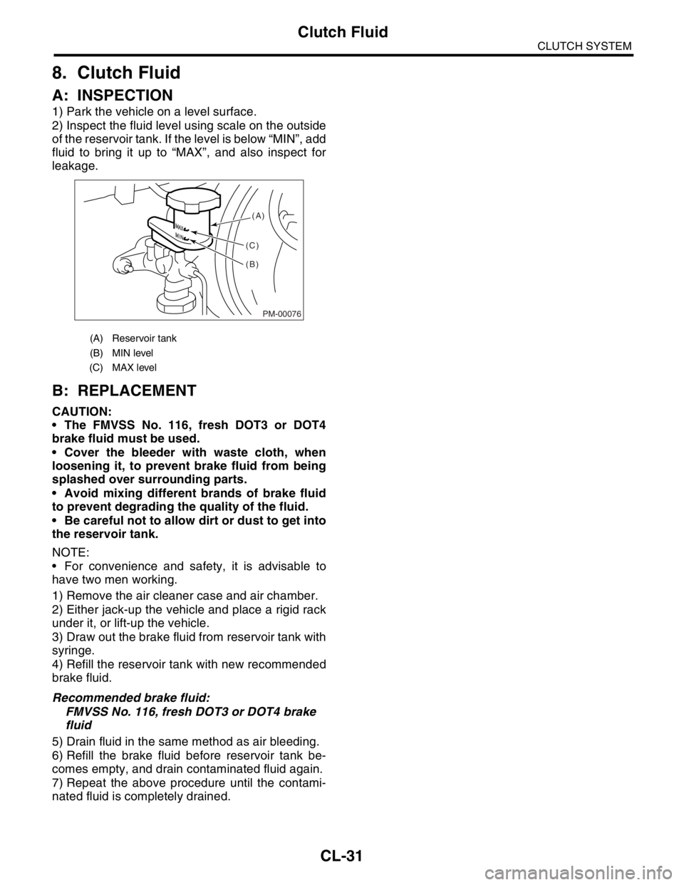
1) Park the vehicle on a level surface.
2) Inspect the fluid level using scale on the outside
of the reservoir tank. If the level is below “MIN”, add
fluid to bring it up to “MAX”, and also inspect for
leakage.
B: REPLACEMENT
CAUTION:
The FMVSS No. 116, fresh DOT3 or DOT4
brake fluid must be used.
Cover the bleeder with waste cloth, when
loosening it, to prevent brake fluid from being
splashed over surrounding parts.
Avoid mixing different brands of brake fluid
to prevent degrading the quality of the fluid.
Be careful not to allow dirt or dust to get into
the reservoir tank.
NOTE:
For convenience and safety, it is advisable to
have two men working.
1) Remove the air cleaner case and air chamber.
2) Either jack-up the vehicle and place a rigid rack
under it, or lift-up the vehicle.
3) Draw out the brake fluid from reservoir tank with
syringe.
4) Refill the reservoir tank with new recommended
brake fluid.
Recommended brake fluid:
FMVSS No. 116, fresh DOT3 or DOT4 brake
fluid
5) Drain fluid in the same method as air bleeding.
6) Refill the brake fluid before reservoir tank be-
comes empty, and drain contaminated fluid again.
7) Repeat the above procedure until the contami-
nated fluid is completely drained.
(A) Reservoir tank
(B) MIN level
(C) MAX level
PM-00076
(A)
(B) (C)
Page 2858 of 2870

CL-32
CLUTCH SYSTEM
Clutch Fluid Air Bleeding
9. Clutch Fluid Air Bleeding
A: PROCEDURE
1. NON-TURBO MODEL
NOTE:
Bleed air from the oil line with help of co-worker.
1) Remove the air cleaner case and air intake duct.
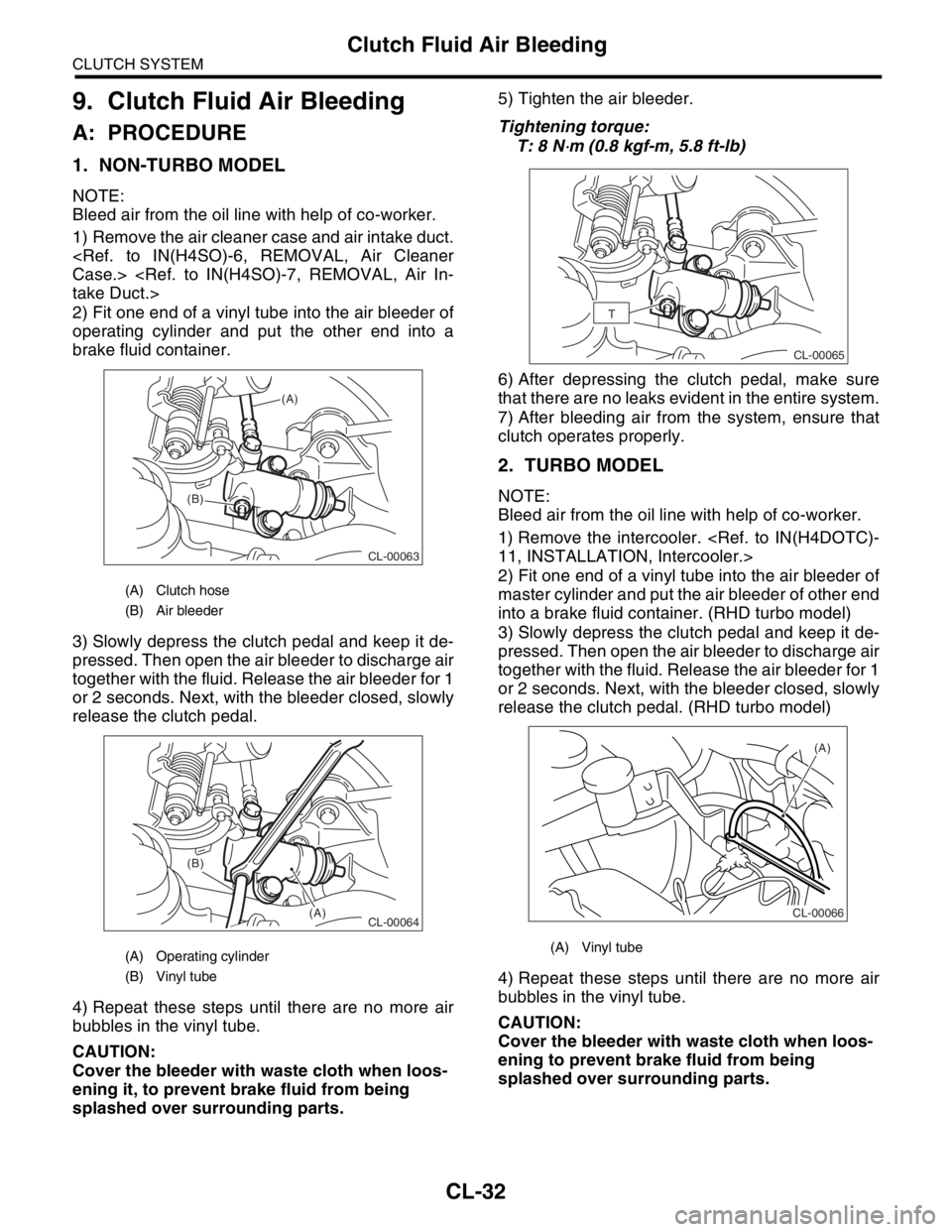
2) Fit one end of a vinyl tube into the air bleeder of
operating cylinder and put the other end into a
brake fluid container.
3) Slowly depress the clutch pedal and keep it de-
pressed. Then open the air bleeder to discharge air
together with the fluid. Release the air bleeder for 1
or 2 seconds. Next, with the bleeder closed, slowly
release the clutch pedal.
4) Repeat these steps until there are no more air
bubbles in the vinyl tube.
CAUTION:
Cover the bleeder with waste cloth when loos-
ening it, to prevent brake fluid from being
splashed over surrounding parts.5) Tighten the air bleeder.
Tightening torque:
T: 8 N
⋅m (0.8 kgf-m, 5.8 ft-lb)
6) After depressing the clutch pedal, make sure
that there are no leaks evident in the entire system.
7) After bleeding air from the system, ensure that
clutch operates properly.
2. TURBO MODEL
NOTE:
Bleed air from the oil line with help of co-worker.
1) Remove the intercooler.
2) Fit one end of a vinyl tube into the air bleeder of
master cylinder and put the air bleeder of other end
into a brake fluid container. (RHD turbo model)
3) Slowly depress the clutch pedal and keep it de-
pressed. Then open the air bleeder to discharge air
together with the fluid. Release the air bleeder for 1
or 2 seconds. Next, with the bleeder closed, slowly
release the clutch pedal. (RHD turbo model)
4) Repeat these steps until there are no more air
bubbles in the vinyl tube.
CAUTION:
Cover the bleeder with waste cloth when loos-
ening to prevent brake fluid from being
splashed over surrounding parts.
(A) Clutch hose
(B) Air bleeder
(A) Operating cylinder
(B) Vinyl tube
CL-00063
(B)(A)
CL-00064
(B)
(A)
(A) Vinyl tube
CL-00065
T
(A)
CL-00066
Page 2859 of 2870

CL-33
CLUTCH SYSTEM
Clutch Fluid Air Bleeding
5) Tighten the air bleeder. (RHD turbo model)
Tightening torque:
T: 8 N
⋅m (0.8 kgf-m, 5.8 ft-lb)
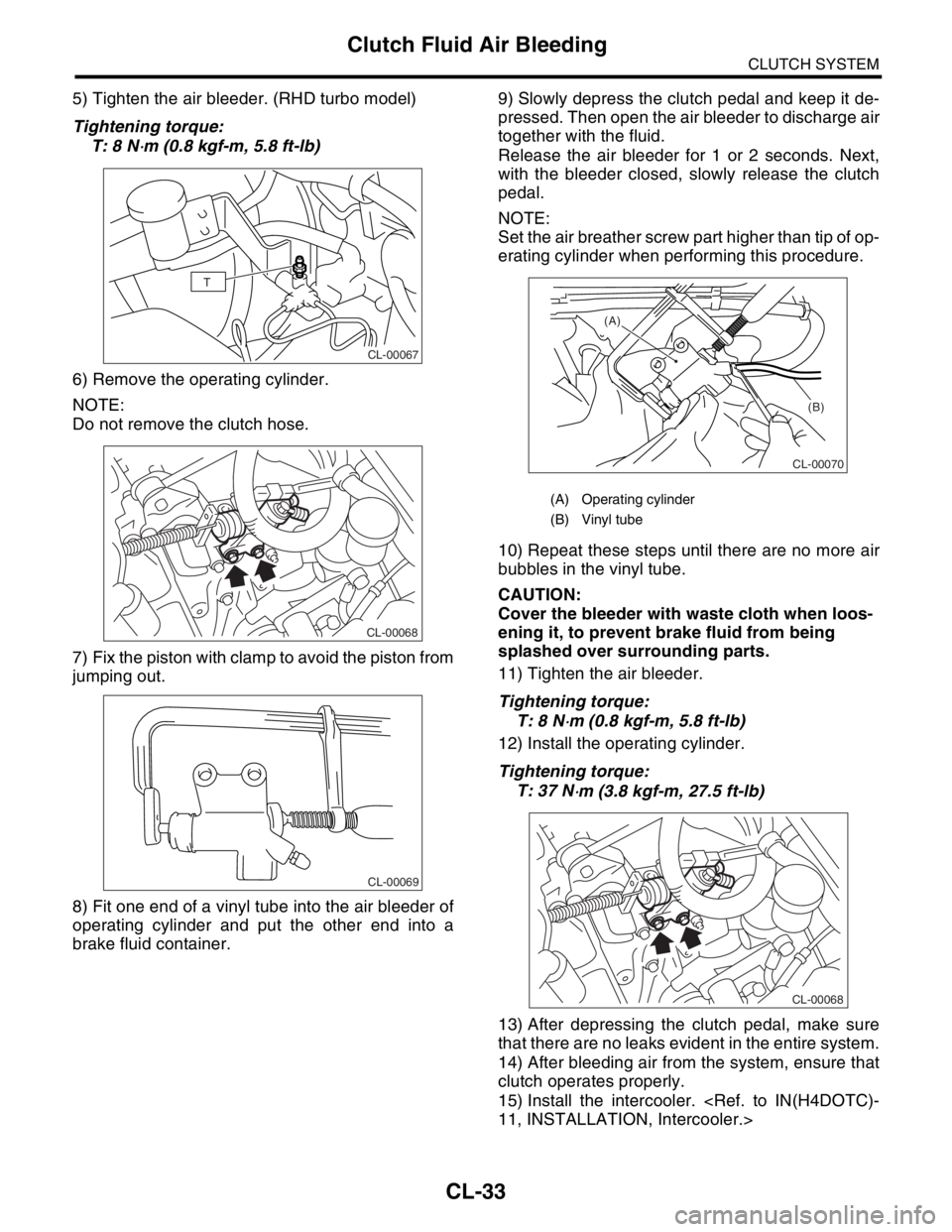
6) Remove the operating cylinder.
NOTE:
Do not remove the clutch hose.
7) Fix the piston with clamp to avoid the piston from
jumping out.
8) Fit one end of a vinyl tube into the air bleeder of
operating cylinder and put the other end into a
brake fluid container.9) Slowly depress the clutch pedal and keep it de-
pressed. Then open the air bleeder to discharge air
together with the fluid.
Release the air bleeder for 1 or 2 seconds. Next,
with the bleeder closed, slowly release the clutch
pedal.
NOTE:
Set the air breather screw part higher than tip of op-
erating cylinder when performing this procedure.
10) Repeat these steps until there are no more air
bubbles in the vinyl tube.
CAUTION:
Cover the bleeder with waste cloth when loos-
ening it, to prevent brake fluid from being
splashed over surrounding parts.
11) Tighten the air bleeder.
Tightening torque:
T: 8 N
⋅m (0.8 kgf-m, 5.8 ft-lb)
12) Install the operating cylinder.
Tightening torque:
T: 37 N
⋅m (3.8 kgf-m, 27.5 ft-lb)
13) After depressing the clutch pedal, make sure
that there are no leaks evident in the entire system.
14) After bleeding air from the system, ensure that
clutch operates properly.
15) Install the intercooler.
CL-00067
T
CL-00068
CL-00069
(A) Operating cylinder
(B) Vinyl tube
CL-00070
(B) (A)
CL-00068