2004 SUBARU FORESTER weight
[x] Cancel search: weightPage 773 of 2870
PM-36
PERIODIC MAINTENANCE SERVICE
Suspension
22.Suspension
A: INSPECTION
1. SUSPENSION BALL JOINT
1) Jack-up the vehicle until front wheels are off
ground.
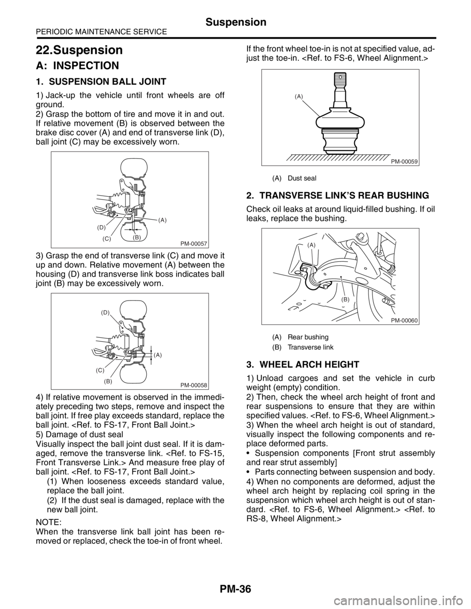
2) Grasp the bottom of tire and move it in and out.
If relative movement (B) is observed between the
brake disc cover (A) and end of transverse link (D),
ball joint (C) may be excessively worn.
3) Grasp the end of transverse link (C) and move it
up and down. Relative movement (A) between the
housing (D) and transverse link boss indicates ball
joint (B) may be excessively worn.
4) If relative movement is observed in the immedi-
ately preceding two steps, remove and inspect the
ball joint. If free play exceeds standard, replace the
ball joint.
5) Damage of dust seal
Visually inspect the ball joint dust seal. If it is dam-
aged, remove the transverse link.
ball joint.
(1) When looseness exceeds standard value,
replace the ball joint.
(2) If the dust seal is damaged, replace with the
new ball joint.
NOTE:
When the transverse link ball joint has been re-
moved or replaced, check the toe-in of front wheel. If the front wheel toe-in is not at specified value, ad-
just the toe-in.
2. TRANSVERSE LINK’S REAR BUSHING
Check oil leaks at around liquid-filled bushing. If oil
leaks, replace the bushing.
3. WHEEL ARCH HEIGHT
1) Unload cargoes and set the vehicle in curb
weight (empty) condition.
2) Then, check the wheel arch height of front and
rear suspensions to ensure that they are within
specified values.
3) When the wheel arch height is out of standard,
visually inspect the following components and re-
place deformed parts.
Suspension components [Front strut assembly
and rear strut assembly]
Parts connecting between suspension and body.
4) When no components are deformed, adjust the
wheel arch height by replacing coil spring in the
suspension which wheel arch height is out of stan-
dard.
PM-00057
(A)
(B)
(C) (D)
PM-00058
(A)
(B) (C)(D)
(A) Dust seal
(A) Rear bushing
(B) Transverse link
PM-00059
(A)
PM-00060
(A)
(B)
Page 906 of 2870
ME(H4SO)-37
MECHANICAL
Engine Assembly
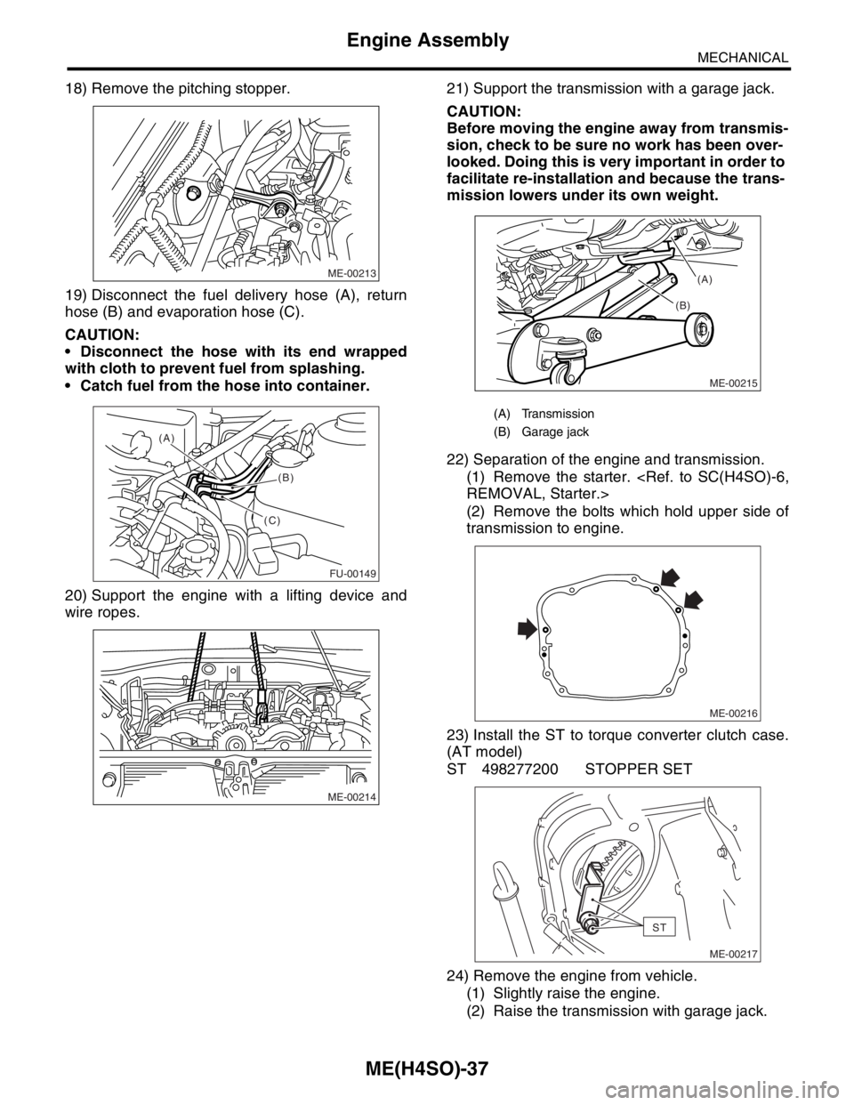
18) Remove the pitching stopper.
19) Disconnect the fuel delivery hose (A), return
hose (B) and evaporation hose (C).
CAUTION:
Disconnect the hose with its end wrapped
with cloth to prevent fuel from splashing.
Catch fuel from the hose into container.
20) Support the engine with a lifting device and
wire ropes.21) Support the transmission with a garage jack.
CAUTION:
Before moving the engine away from transmis-
sion, check to be sure no work has been over-
looked. Doing this is very important in order to
facilitate re-installation and because the trans-
mission lowers under its own weight.
22) Separation of the engine and transmission.
(1) Remove the starter.
(2) Remove the bolts which hold upper side of
transmission to engine.
23) Install the ST to torque converter clutch case.
(AT model)
ST 498277200 STOPPER SET
24) Remove the engine from vehicle.
(1) Slightly raise the engine.
(2) Raise the transmission with garage jack.
ME-00213
FU-00149
(A)
(B)
(C)
ME-00214
(A) Transmission
(B) Garage jack
ME-00215
(B)(A)
ME-00216
ST
ME-00217
Page 1503 of 2870
ME(H4DOTC)-45
MECHANICAL
Engine Assembly
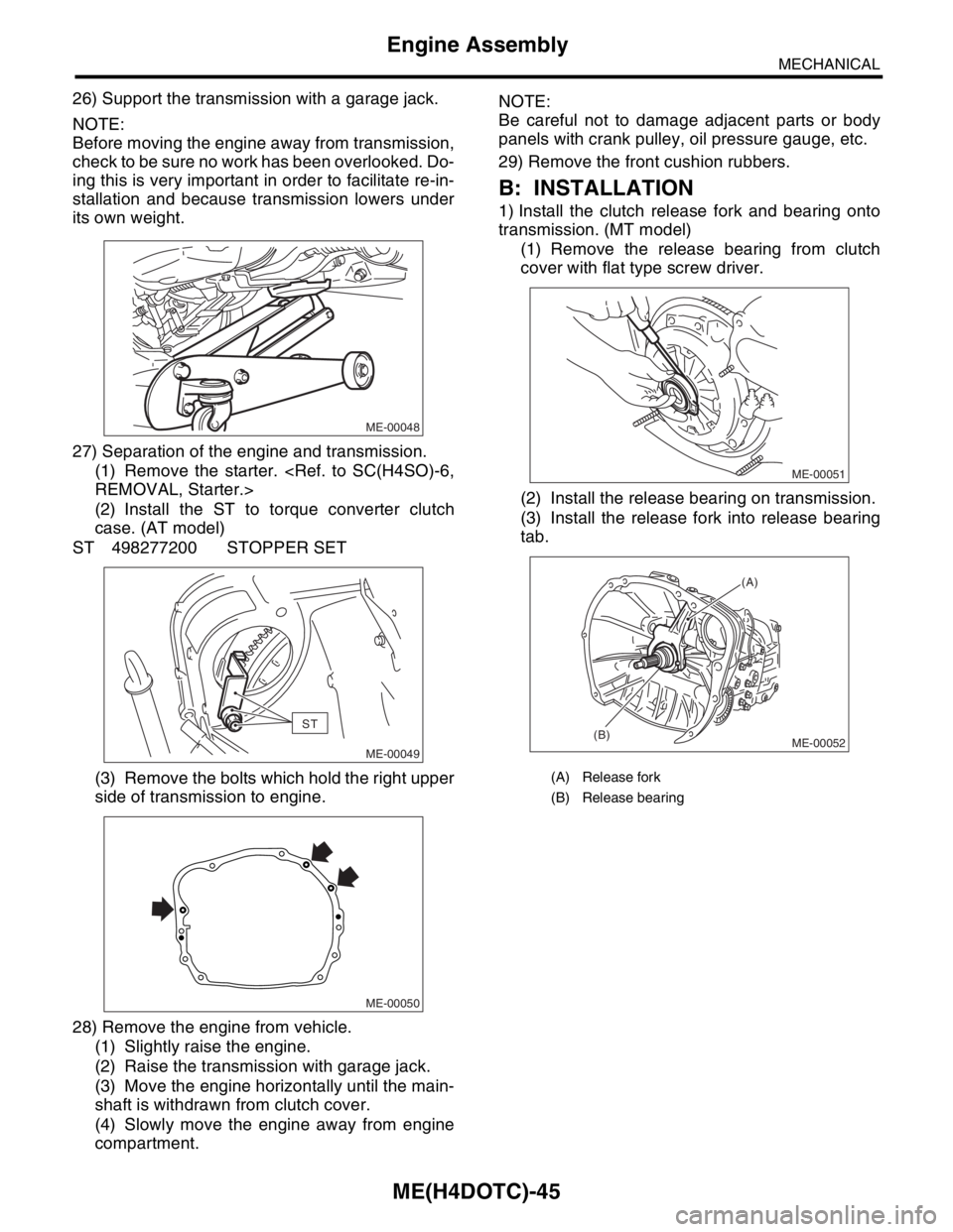
26) Support the transmission with a garage jack.
NOTE:
Before moving the engine away from transmission,
check to be sure no work has been overlooked. Do-
ing this is very important in order to facilitate re-in-
stallation and because transmission lowers under
its own weight.
27) Separation of the engine and transmission.
(1) Remove the starter.
(2) Install the ST to torque converter clutch
case. (AT model)
ST 498277200 STOPPER SET
(3) Remove the bolts which hold the right upper
side of transmission to engine.
28) Remove the engine from vehicle.
(1) Slightly raise the engine.
(2) Raise the transmission with garage jack.
(3) Move the engine horizontally until the main-
shaft is withdrawn from clutch cover.
(4) Slowly move the engine away from engine
compartment.NOTE:
Be careful not to damage adjacent parts or body
panels with crank pulley, oil pressure gauge, etc.
29) Remove the front cushion rubbers.
B: INSTALLATION
1) Install the clutch release fork and bearing onto
transmission. (MT model)
(1) Remove the release bearing from clutch
cover with flat type screw driver.
(2) Install the release bearing on transmission.
(3) Install the release fork into release bearing
tab.
ME-00048
ST
ME-00049
ME-00050
(A) Release fork
(B) Release bearing
ME-00051
ME-00052
(A)
(B)
Page 2297 of 2870
![SUBARU FORESTER 2004 Service Repair Manual CS-12
CONTROL SYSTEM
Select Lever
D: ASSEMBLY
1) Clean all parts before assembly.
2) Apply grease [SUNLIGHT 2 (Part No.
003602010) or equivalent] to each part. <Ref. to
CS-3, AT SELECT LEVER, COMPONEN](/manual-img/17/57426/w960_57426-2296.png "SUBARU FORESTER 2004 Service Repair Manual CS-12
CONTROL SYSTEM
Select Lever
D: ASSEMBLY
1) Clean all parts before assembly.
2) Apply grease [SUNLIGHT 2 (Part No.
003602010) or equivalent] to each part. <Ref. to
CS-3, AT SELECT LEVER, COMPONEN")
CS-12
CONTROL SYSTEM
Select Lever
D: ASSEMBLY
1) Clean all parts before assembly.
2) Apply grease [SUNLIGHT 2 (Part No.
003602010) or equivalent] to each part.
al Description.>
CAUTION:
Apply grease [SUNCALL] around the axle of lock
plate (Turbo model). Apply grease to only indi-
cated portion.
3) Assemble is in the reverse order of disassembly.
NOTE:
Refer to “COMPOTNENT” for tightening torque.
Tighten the lock plate bolt uniformly. After installa-
tion, put the base plate upside down, and then push
the lock plate up. Make sure the lock plate falls by its
weight when releasing it. If not, retighten the bolt.
4) After completion of fitting, transfer the select le-
ver to range “P” — “1”, then check the indicator and
select lever are matched, the pointer and position
mark are matched and the operating force.
E: INSPECTION
1) Inspect the removed parts by comparing with
new ones for deformation, damage and wear. Cor-
rect or replace if defective.
2) Confirm the following parts for operating condi-
tion before assembly. Moving condition of the se-
lect lever assembly, it should move smoothly.
CS-00355
CS-00356
Page 2440 of 2870
4AT-126
AUTOMATIC TRANSMISSION
AT Main Case
B: INSTALLATION
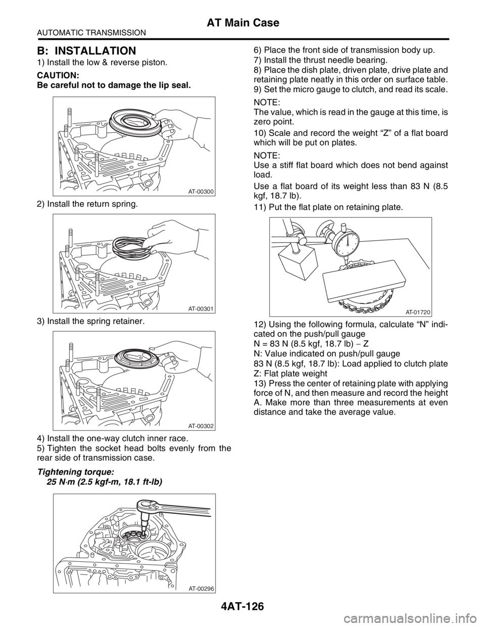
1) Install the low & reverse piston.
CAUTION:
Be careful not to damage the lip seal.
2) Install the return spring.
3) Install the spring retainer.
4) Install the one-way clutch inner race.
5) Tighten the socket head bolts evenly from the
rear side of transmission case.
Tightening torque:
25 N
⋅m (2.5 kgf-m, 18.1 ft-lb)6) Place the front side of transmission body up.
7) Install the thrust needle bearing.
8) Place the dish plate, driven plate, drive plate and
retaining plate neatly in this order on surface table.
9) Set the micro gauge to clutch, and read its scale.
NOTE:
The value, which is read in the gauge at this time, is
zero point.
10) Scale and record the weight “Z” of a flat board
which will be put on plates.
NOTE:
Use a stiff flat board which does not bend against
load.
Use a flat board of its weight less than 83 N (8.5
kgf, 18.7 lb).
11) Put the flat plate on retaining plate.
12) Using the following formula, calculate “N” indi-
cated on the push/pull gauge
N = 83 N (8.5 kgf, 18.7 lb) − Z
N: Value indicated on push/pull gauge
83 N (8.5 kgf, 18.7 lb): Load applied to clutch plate
Z: Flat plate weight
13) Press the center of retaining plate with applying
force of N, and then measure and record the height
A. Make more than three measurements at even
distance and take the average value.
AT-00300
AT-00301
AT-00302
AT-00296
AT-01720
Page 2730 of 2870
5MT-18
MANUAL TRANSMISSION AND DIFFERENTIAL
General Description
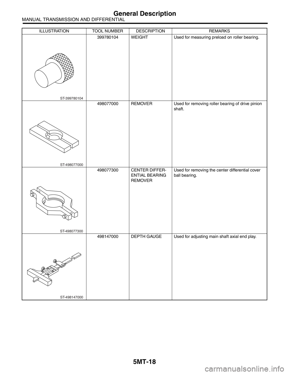
399780104 WEIGHT Used for measuring preload on roller bearing.
498077000 REMOVER Used for removing roller bearing of drive pinion
shaft.
498077300 CENTER DIFFER-
ENTIAL BEARING
REMOVERUsed for removing the center differential cover
ball bearing.
498147000 DEPTH GAUGE Used for adjusting main shaft axial end play. ILLUSTRATION TOOL NUMBER DESCRIPTION REMARKS
ST-399780104
ST-498077000
ST-498077300
ST-498147000
Page 2778 of 2870
5MT-65
MANUAL TRANSMISSION AND DIFFERENTIAL
Transmission Case
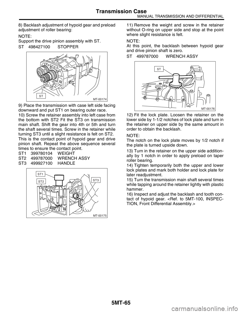
8) Backlash adjustment of hypoid gear and preload
adjustment of roller bearing:
NOTE:
Support the drive pinion assembly with ST.
ST 498427100 STOPPER
9) Place the transmission with case left side facing
downward and put ST1 on bearing outer race.
10) Screw the retainer assembly into left case from
the bottom with ST2 Fit the ST3 on transmission
main shaft. Shift the gear into 4th or 5th and turn
the shaft several times. Screw in the retainer while
turning ST3 until a slight resistance is felt on ST2.
This is the contact point of hypoid gear and drive
pinion shaft. Repeat the above sequence several
times to ensure the contact point.
ST1 399780104 WEIGHT
ST2 499787000 WRENCH ASSY
ST3 499927100 HANDLE11) Remove the weight and screw in the retainer
without O-ring on upper side and stop at the point
where slight resistance is felt.
NOTE:
At this point, the backlash between hypoid gear
and drive pinion shaft is zero.
ST 499787000 WRENCH ASSY
12) Fit the lock plate. Loosen the retainer on the
lower side by 1-1/2 notches of lock plate and turn in
the retainer on upper side by the same amount in
order to obtain the backlash.
NOTE:
The notch on the lock plate moves by 1/2 notch if
the plate is turned upside down.
13) Turn in the retainer on the upper side addition-
ally by 1 notch in order to apply preload on taper
roller bearing.
14) Tighten temporarily both the upper and lower
lock plates and mark both holder and lock plate for
later readjustment.
15) Turn the transmission main shaft several times
while tapping around the retainer lightly with plastic
hammer.
16) Inspect and adjust the backlash and tooth con-
tact of hypoid gear.
MT-00174ST
MT-00175
ST3ST2
ST1
MT-00176
ST
Page 2780 of 2870
5MT-67
MANUAL TRANSMISSION AND DIFFERENTIAL
Transmission Case
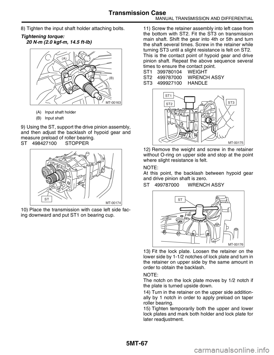
8) Tighten the input shaft holder attaching bolts.
Tightening torque:
20 N·m (2.0 kgf-m, 14.5 ft-lb)
9) Using the ST, support the drive pinion assembly,
and then adjust the backlash of hypoid gear and
measure preload of roller bearing.
ST 498427100 STOPPER
10) Place the transmission with case left side fac-
ing downward and put ST1 on bearing cup.11) Screw the retainer assembly into left case from
the bottom with ST2. Fit the ST3 on transmission
main shaft. Shift the gear into 4th or 5th and turn
the shaft several times. Screw in the retainer while
turning ST3 until a slight resistance is felt on ST2.
This is the contact point of hypoid gear and drive
pinion shaft. Repeat the above sequence several
times to ensure the contact point.
ST1 399780104 WEIGHT
ST2 499787000 WRENCH ASSY
ST3 499927100 HANDLE
12) Remove the weight and screw in the retainer
without O-ring on upper side and stop at the point
where slight resistance is felt.
NOTE:
At this point, the backlash between hypoid gear
and drive pinion shaft is zero.
ST 499787000 WRENCH ASSY
13) Fit the lock plate. Loosen the retainer on the
lower side by 1-1/2 notches of lock plate and turn in
the retainer on upper side by the same amount in
order to obtain the backlash.
NOTE:
The notch on the lock plate moves by 1/2 notch if
the plate is turned upside down.
14) Turn in the retainer on the upper side addition-
ally by 1 notch in order to apply preload on taper
roller bearing.
15) Tighten temporarily both the upper and lower
lock plates and mark both holder and lock plate for
later readjustment.
(A) Input shaft holder
(B) Input shaft
MT-00163
(A)
(B)
MT-00174ST
MT-00175
ST3ST2
ST1
MT-00176
ST