2004 SUBARU FORESTER valve
[x] Cancel search: valvePage 23 of 2870
AC-21
HVAC SYSTEM (HEATER, VENTILATOR AND A/C)
General Description
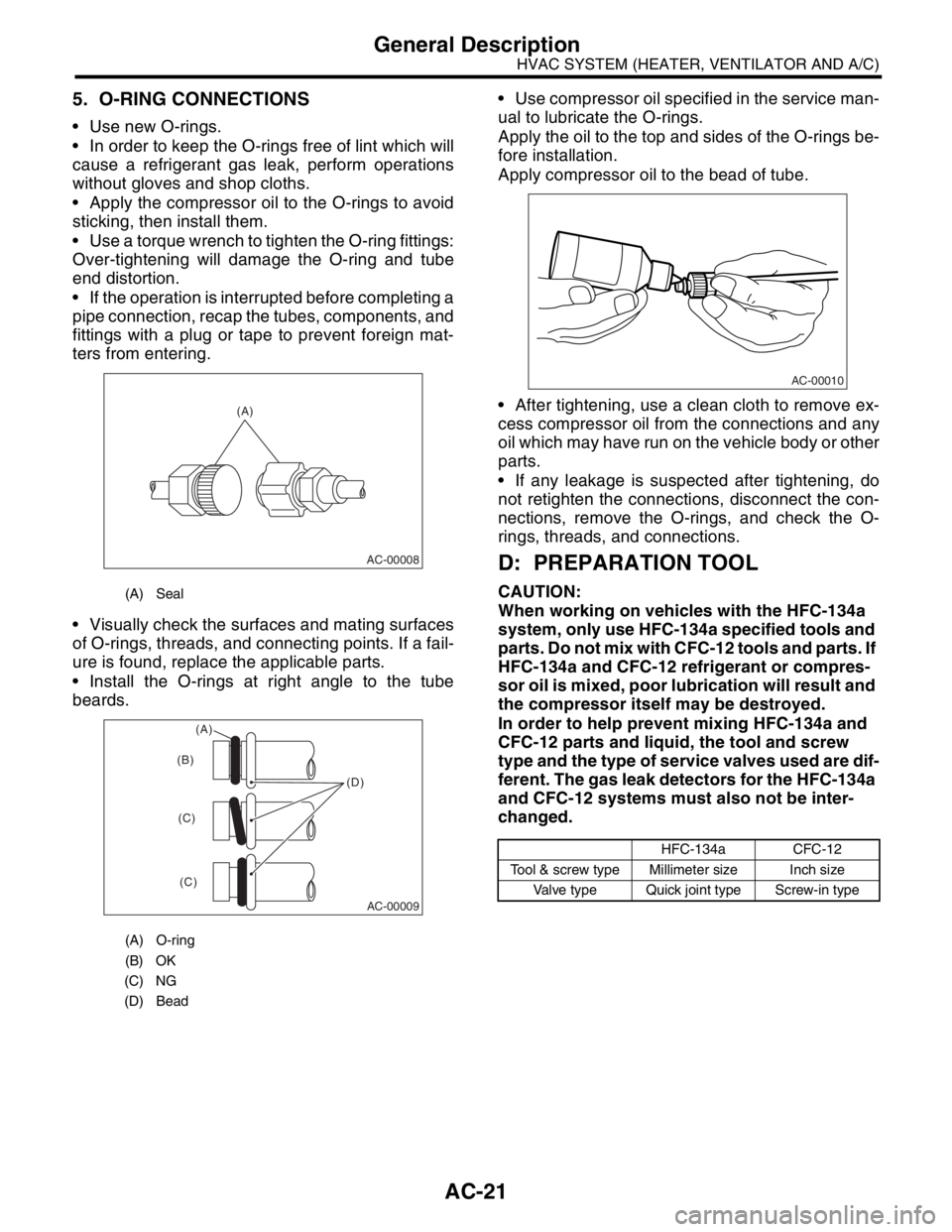
5. O-RING CONNECTIONS
Use new O-rings.
In order to keep the O-rings free of lint which will
cause a refrigerant gas leak, perform operations
without gloves and shop cloths.
Apply the compressor oil to the O-rings to avoid
sticking, then install them.
Use a torque wrench to tighten the O-ring fittings:
Over-tightening will damage the O-ring and tube
end distortion.
If the operation is interrupted before completing a
pipe connection, recap the tubes, components, and
fittings with a plug or tape to prevent foreign mat-
ters from entering.
Visually check the surfaces and mating surfaces
of O-rings, threads, and connecting points. If a fail-
ure is found, replace the applicable parts.
Install the O-rings at right angle to the tube
beards. Use compressor oil specified in the service man-
ual to lubricate the O-rings.
Apply the oil to the top and sides of the O-rings be-
fore installation.
Apply compressor oil to the bead of tube.
After tightening, use a clean cloth to remove ex-
cess compressor oil from the connections and any
oil which may have run on the vehicle body or other
parts.
If any leakage is suspected after tightening, do
not retighten the connections, disconnect the con-
nections, remove the O-rings, and check the O-
rings, threads, and connections.
D: PREPARATION TOOL
CAUTION:
When working on vehicles with the HFC-134a
system, only use HFC-134a specified tools and
parts. Do not mix with CFC-12 tools and parts. If
HFC-134a and CFC-12 refrigerant or compres-
sor oil is mixed, poor lubrication will result and
the compressor itself may be destroyed.
In order to help prevent mixing HFC-134a and
CFC-12 parts and liquid, the tool and screw
type and the type of service valves used are dif-
ferent. The gas leak detectors for the HFC-134a
and CFC-12 systems must also not be inter-
changed.(A) Seal
(A) O-ring
(B) OK
(C) NG
(D) Bead
(A)
AC-00008
AC-00009
(D) (B)
(C)
(C)
(A)
HFC-134a CFC-12
Tool & screw type Millimeter size Inch size
Valve type Quick joint type Screw-in type
AC-00010
Page 27 of 2870

AC-25
HVAC SYSTEM (HEATER, VENTILATOR AND A/C)
Refrigerant Pressure with Manifold Gauge Set
2. Refrigerant Pressure with Manifold Gauge Set
A: OPERATION
1) Place the vehicle in the shade and draftless condition.
2) Connect the manifold gauge set.
3) Open the front windows and close all doors.
4) Open the hood.
5) Increase the engine speed to 1,500 rpm.
6) Turn ON the A/C switch.
7) Turn the temperature control dial to MAX COOL.
8) Set the air inlet select switch to RECIRC position.
9) Turn the fan dial to HI.
10) Read the gauge.
Standard:
Low pressure: 127 — 196 kPa (1.3 — 2.0 kg/cm
2, 18 — 28 psi)
High pressure: 1,471 — 1, 667 kPa (15 — 17 kg/cm2, 213 — 242 psi)
Ambient temperature: 30 — 35
°C (86 — 95°F)
B: INSPECTION
Symptom Probable cause Repair order
High-pressure side is unusually high. Defective condenser fan motor
Clogged condenser fin
Too much refrigerant
Air inside the system
Defective receiver dryer Replace the fan motor.
Clean the condenser fin.
Discharge refrigerant.
Replace the receiver dryer.
After reevacuating the receiver dryer,
charge appropriate amount of refriger-
ant.
High-pressure side is unusually low. Defective compressor
Not enough refrigerant
Clogged expansion valve
Expansion valve frozen temporarily by
moisture Replace the compressor.
Check for leaks.
Replace the expansion valve.
Fully evacuate the expansion valve.
Low-pressure side is unusually high. Defective compressor
Defective expansion valve
Too much refrigerant Replace the compressor.
Replace the expansion valve.
Discharge refrigerant.
Low-pressure side is unusually low. Not enough refrigerant
Clogged expansion valve
Expansion valve frozen temporarily by
moisture
Saturated receiver dryer Check for leaks.
Replace the expansion valve.
Replace the receiver dryer.
Page 28 of 2870
AC-26
HVAC SYSTEM (HEATER, VENTILATOR AND A/C)
Refrigerant Recovery Procedure
3. Refrigerant Recovery Proce-
dure
A: OPERATION
CAUTION:
During operation, be sure to wear safety gog-
gles and protective gloves.
Connect the refrigerant recovery system with
the manifold gauge set to discharge the refrig-
erant from the A/C system and reuse it.
When reusing the discharged refrigerant, keep
service cans on hand. Because the discharge
rate with the recovery system is approx. 90%, ser-
vice cans are necessary to charge the refrigerant.
Follow the detailed operation procedure de-
scribed in the operation manual attached to the
refrigerant recovery system.
1) Perform the compressor oil return operation.
2) Stop the engine.
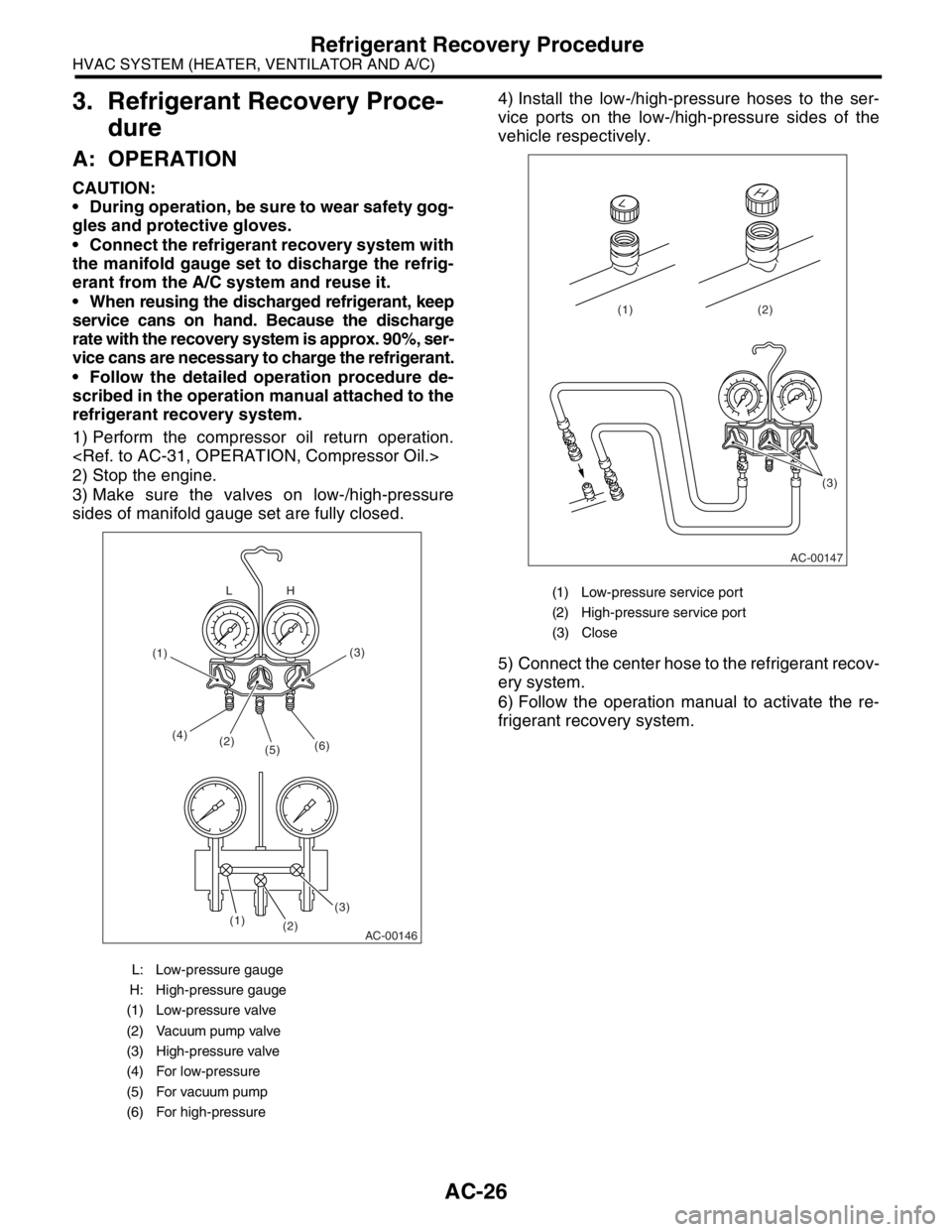
3) Make sure the valves on low-/high-pressure
sides of manifold gauge set are fully closed.4) Install the low-/high-pressure hoses to the ser-
vice ports on the low-/high-pressure sides of the
vehicle respectively.
5) Connect the center hose to the refrigerant recov-
ery system.
6) Follow the operation manual to activate the re-
frigerant recovery system.
L: Low-pressure gauge
H: High-pressure gauge
(1) Low-pressure valve
(2) Vacuum pump valve
(3) High-pressure valve
(4) For low-pressure
(5) For vacuum pump
(6) For high-pressure
AC-00146
(2) (4)
(5)(6)
(3)(3)
(2) (1)H L
(1)
(1) Low-pressure service port
(2) High-pressure service port
(3) Close
AC-00147
(3) (2) (1)
Page 29 of 2870
AC-27
HVAC SYSTEM (HEATER, VENTILATOR AND A/C)
Refrigerant Charging Procedure
4. Refrigerant Charging Proce-
dure
A: OPERATION
CAUTION:
During operation, be sure to wear safety gog-
gles and protective gloves.
If air is mixed in refrigeration cycle, poor cool-
ing may result, and also if moisture is mixed in re-
frigeration cycle, clogging (freezing) or rust may
result.
Before charging the refrigerant, evacuate the
system using vacuum pump to remove air and
moisture in the system. Moisture can be evapo-
rated and removed easily even at normal tem-
perature, if the system is evacuated using
vacuum pump.
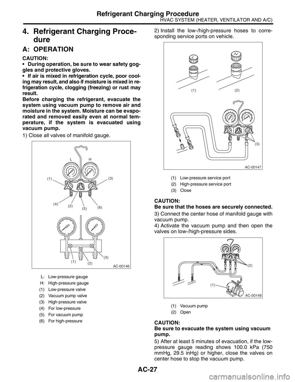
1) Close all valves of manifold gauge.2) Install the low-/high-pressure hoses to corre-
sponding service ports on vehicle.
CAUTION:
Be sure that the hoses are securely connected.
3) Connect the center hose of manifold gauge with
vacuum pump.
4) Activate the vacuum pump and then open the
valves on low-/high-pressure sides.
CAUTION:
Be sure to evacuate the system using vacuum
pump.
5) After at least 5 minutes of evacuation, if the low-
pressure gauge reading shows 100.0 kPa (750
mmHg, 29.5 inHg) or higher, close the valves on
center hose to stop the vacuum pump.
L: Low-pressure gauge
H: High-pressure gauge
(1) Low-pressure valve
(2) Vacuum pump valve
(3) High-pressure valve
(4) For low-pressure
(5) For vacuum pump
(6) For high-pressure
AC-00146
(2) (4)
(5)(6)
(3)(3)
(2) (1)H L
(1)
(1) Low-pressure service port
(2) High-pressure service port
(3) Close
(1) Vacuum pump
(2) Open
AC-00147
(3) (2) (1)
AC-00148
(1)(2)
Page 30 of 2870
AC-28
HVAC SYSTEM (HEATER, VENTILATOR AND A/C)
Refrigerant Charging Procedure
6) Leave it at least 5 to 10 minutes after closing the
valves on low-/high-pressure sides, and then check
the low-pressure gauge reading for any changes.
When the gauge reading changes, this is a sign of
leakage. Check the pipe or hose connector points,
and repair if necessary. Repeat the procedure from
1) after repairing the faulty part.
7) If there are no leaks, further evacuate the sys-
tem 20 to 30 minutes.
8) Close all valves and stop the vacuum pump.
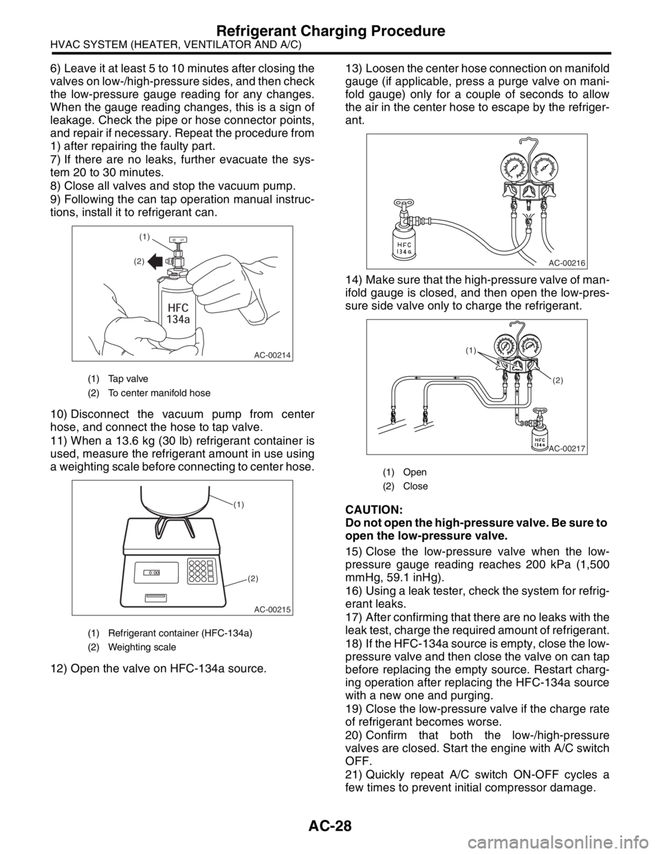
9) Following the can tap operation manual instruc-
tions, install it to refrigerant can.
10) Disconnect the vacuum pump from center
hose, and connect the hose to tap valve.
11) When a 13.6 kg (30 lb) refrigerant container is
used, measure the refrigerant amount in use using
a weighting scale before connecting to center hose.
12) Open the valve on HFC-134a source.13) Loosen the center hose connection on manifold
gauge (if applicable, press a purge valve on mani-
fold gauge) only for a couple of seconds to allow
the air in the center hose to escape by the refriger-
ant.
14) Make sure that the high-pressure valve of man-
ifold gauge is closed, and then open the low-pres-
sure side valve only to charge the refrigerant.
CAUTION:
Do not open the high-pressure valve. Be sure to
open the low-pressure valve.
15) Close the low-pressure valve when the low-
pressure gauge reading reaches 200 kPa (1,500
mmHg, 59.1 inHg).
16) Using a leak tester, check the system for refrig-
erant leaks.
17) After confirming that there are no leaks with the
leak test, charge the required amount of refrigerant.
18) If the HFC-134a source is empty, close the low-
pressure valve and then close the valve on can tap
before replacing the empty source. Restart charg-
ing operation after replacing the HFC-134a source
with a new one and purging.
19) Close the low-pressure valve if the charge rate
of refrigerant becomes worse.
20) Confirm that both the low-/high-pressure
valves are closed. Start the engine with A/C switch
OFF.
21) Quickly repeat A/C switch ON-OFF cycles a
few times to prevent initial compressor damage.
(1) Tap valve
(2) To center manifold hose
(1) Refrigerant container (HFC-134a)
(2) Weighting scale
AC-00214
(1)
(2)
AC-00215
(1)
(2)
(1) Open
(2) Close
AC-00216
AC-00217
(1)
(2)
Page 31 of 2870

AC-29
HVAC SYSTEM (HEATER, VENTILATOR AND A/C)
Refrigerant Charging Procedure
22) Set up the vehicle to the following status:
A/C switch ON
Engine running at 1,500 rpm
Blower speed setting to “HI”
Temperature setting to “MAX COOL”
Air inlet setting to “RECIRC”
Window open
23) Open the low-pressure valve and charge the
specified amount of refrigerant.
24) Close all valves and disconnect the hoses from
service port after charging the refrigerant.
25) Install the cap to service port.
Page 32 of 2870
AC-30
HVAC SYSTEM (HEATER, VENTILATOR AND A/C)
Refrigerant Leak Check
5. Refrigerant Leak Check
A: INSPECTION
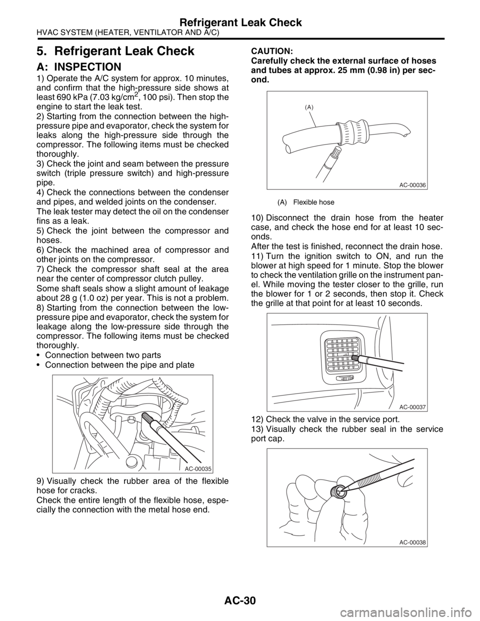
1) Operate the A/C system for approx. 10 minutes,
and confirm that the high-pressure side shows at
least 690 kPa (7.03 kg/cm
2, 100 psi). Then stop the
engine to start the leak test.
2) Starting from the connection between the high-
pressure pipe and evaporator, check the system for
leaks along the high-pressure side through the
compressor. The following items must be checked
thoroughly.
3) Check the joint and seam between the pressure
switch (triple pressure switch) and high-pressure
pipe.
4) Check the connections between the condenser
and pipes, and welded joints on the condenser.
The leak tester may detect the oil on the condenser
fins as a leak.
5) Check the joint between the compressor and
hoses.
6) Check the machined area of compressor and
other joints on the compressor.
7) Check the compressor shaft seal at the area
near the center of compressor clutch pulley.
Some shaft seals show a slight amount of leakage
about 28 g (1.0 oz) per year. This is not a problem.
8) Starting from the connection between the low-
pressure pipe and evaporator, check the system for
leakage along the low-pressure side through the
compressor. The following items must be checked
thoroughly.
Connection between two parts
Connection between the pipe and plate
9) Visually check the rubber area of the flexible
hose for cracks.
Check the entire length of the flexible hose, espe-
cially the connection with the metal hose end.CAUTION:
Carefully check the external surface of hoses
and tubes at approx. 25 mm (0.98 in) per sec-
ond.
10) Disconnect the drain hose from the heater
case, and check the hose end for at least 10 sec-
onds.
After the test is finished, reconnect the drain hose.
11) Turn the ignition switch to ON, and run the
blower at high speed for 1 minute. Stop the blower
to check the ventilation grille on the instrument pan-
el. While moving the tester closer to the grille, run
the blower for 1 or 2 seconds, then stop it. Check
the grille at that point for at least 10 seconds.
12) Check the valve in the service port.
13) Visually check the rubber seal in the service
port cap.
AC-00035
(A) Flexible hose
AC-00036
(A)
AC-00037
AC-00038
Page 41 of 2870
AC-39
HVAC SYSTEM (HEATER, VENTILATOR AND A/C)
Heater Cooling Unit
14.Heater Cooling Unit
A: REMOVAL
1) Disconnect the ground cable from battery.
2) Using the refrigerant recovery system, dis-
charge refrigerant.
3) Drain the engine coolant from radiator.
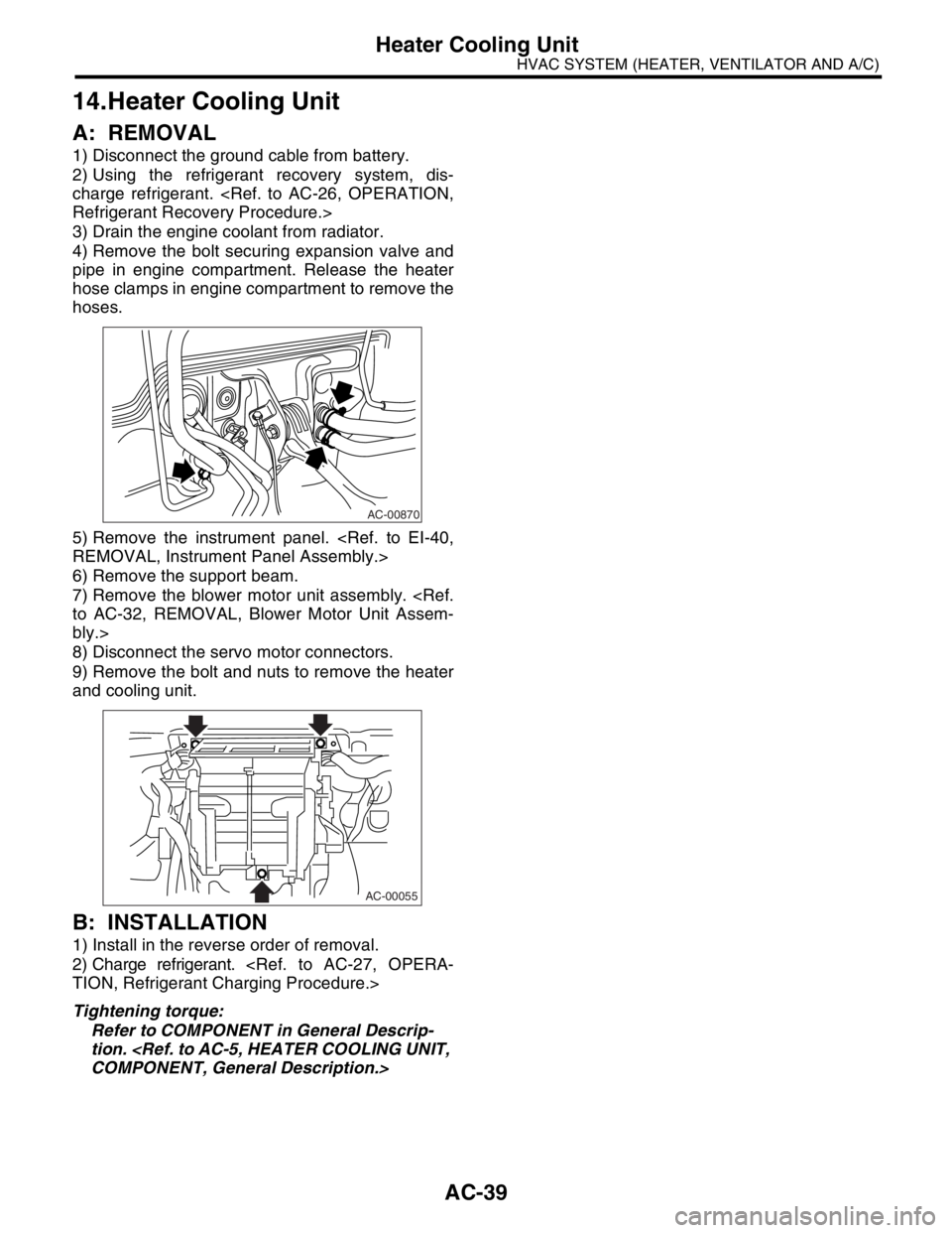
4) Remove the bolt securing expansion valve and
pipe in engine compartment. Release the heater
hose clamps in engine compartment to remove the
hoses.
5) Remove the instrument panel.
6) Remove the support beam.
7) Remove the blower motor unit assembly.
bly.>
8) Disconnect the servo motor connectors.
9) Remove the bolt and nuts to remove the heater
and cooling unit.
B: INSTALLATION
1) Install in the reverse order of removal.
2) Charge refrigerant.
Tightening torque:
Refer to COMPONENT in General Descrip-
tion.
AC-00870
AC-00055