2004 SUBARU FORESTER lights
[x] Cancel search: lightsPage 733 of 2870

PI-10
PRE-DELIVERY INSPECTION
Pre-delivery Inspection
21.KEYLESS ENTRY SYSTEM
Check the keyless entry system operations as fol-
lows:
Fully open all the door windows.
Remove the key from the ignition switch and
close all the doors including rear gate.
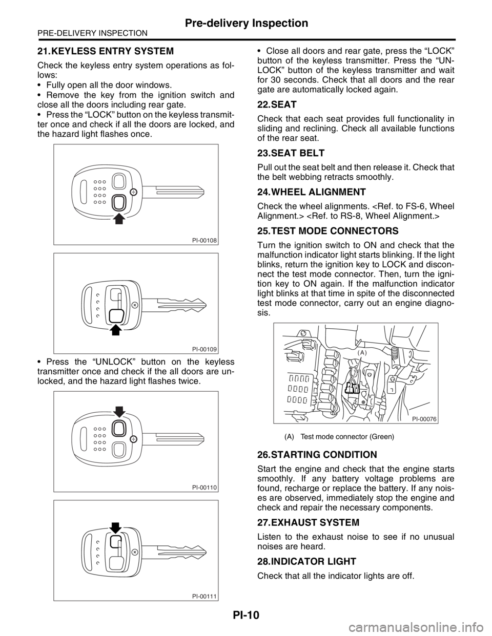
Press the “LOCK” button on the keyless transmit-
ter once and check if all the doors are locked, and
the hazard light flashes once.
Press the “UNLOCK” button on the keyless
transmitter once and check if the all doors are un-
locked, and the hazard light flashes twice. Close all doors and rear gate, press the “LOCK”
button of the keyless transmitter. Press the “UN-
LOCK” button of the keyless transmitter and wait
for 30 seconds. Check that all doors and the rear
gate are automatically locked again.
22.SEAT
Check that each seat provides full functionality in
sliding and reclining. Check all available functions
of the rear seat.
23.SEAT BELT
Pull out the seat belt and then release it. Check that
the belt webbing retracts smoothly.
24.WHEEL ALIGNMENT
Check the wheel alignments.
25.TEST MODE CONNECTORS
Turn the ignition switch to ON and check that the
malfunction indicator light starts blinking. If the light
blinks, return the ignition key to LOCK and discon-
nect the test mode connector. Then, turn the igni-
tion key to ON again. If the malfunction indicator
light blinks at that time in spite of the disconnected
test mode connector, carry out an engine diagno-
sis.
26.STARTING CONDITION
Start the engine and check that the engine starts
smoothly. If any battery voltage problems are
found, recharge or replace the battery. If any nois-
es are observed, immediately stop the engine and
check and repair the necessary components.
27.EXHAUST SYSTEM
Listen to the exhaust noise to see if no unusual
noises are heard.
28.INDICATOR LIGHT
Check that all the indicator lights are off.
PI-00108
PI-00109
PI-00110
PI-00111
(A) Test mode connector (Green)
PI-00076
(A)
Page 734 of 2870

PI-11
PRE-DELIVERY INSPECTION
Pre-delivery Inspection
29.CLOCK
Check the clock for normal operations and enough
accuracy.
30.RADIO
Check the radio for full functionality and normal
noise level. Also check the CD unit operations.
31.FRONT ACCESSORY POWER SUPPLY
SOCKET
Check the front accessory power supply socket op-
erations.
32.LIGHTING SYSTEM
Check the headlight operations.
Check the brake light operations.
Check the other lights for normal operations.
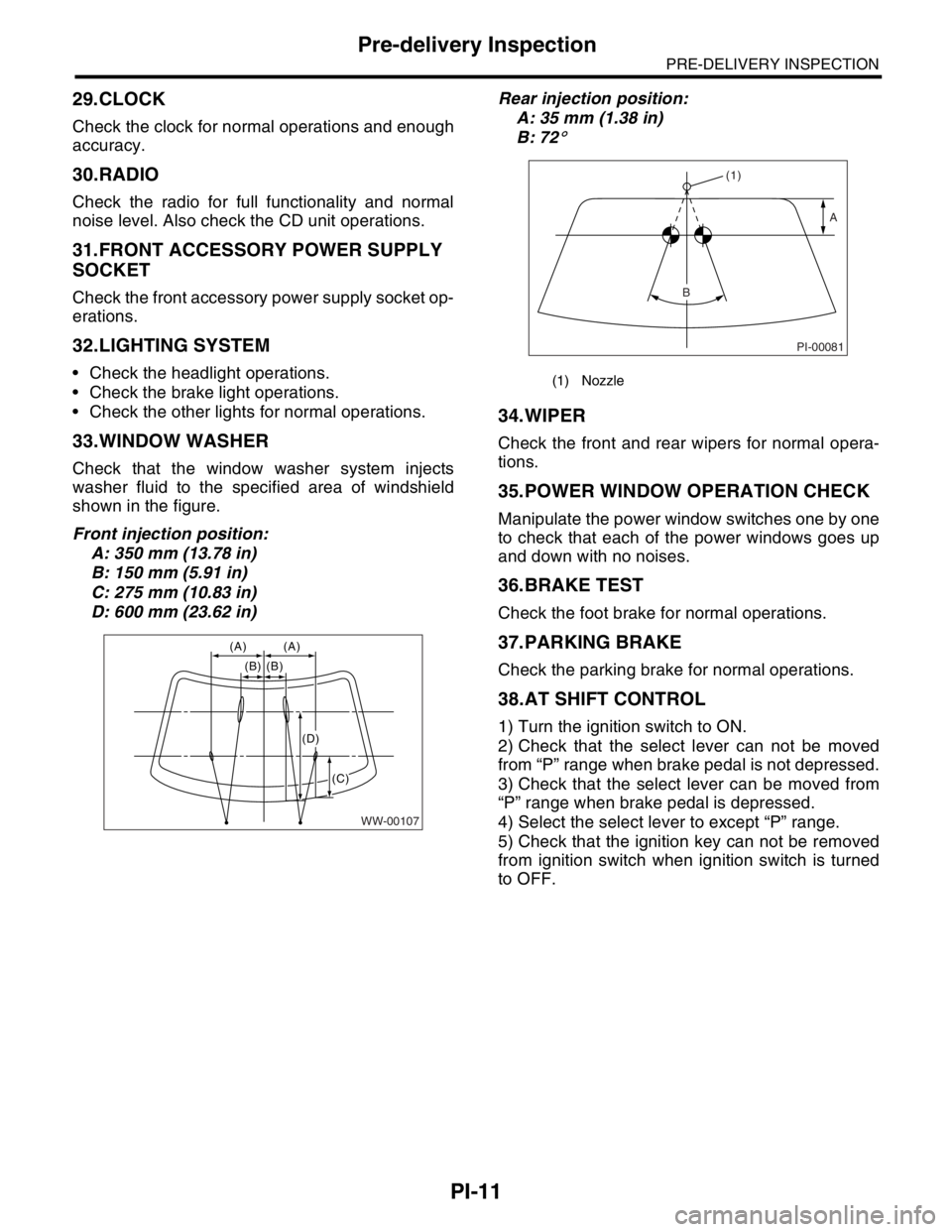
33.WINDOW WASHER
Check that the window washer system injects
washer fluid to the specified area of windshield
shown in the figure.
Front injection position:
A: 350 mm (13.78 in)
B: 150 mm (5.91 in)
C: 275 mm (10.83 in)
D: 600 mm (23.62 in)Rear injection position:
A: 35 mm (1.38 in)
B: 72
°
34.WIPER
Check the front and rear wipers for normal opera-
tions.
35.POWER WINDOW OPERATION CHECK
Manipulate the power window switches one by one
to check that each of the power windows goes up
and down with no noises.
36.BRAKE TEST
Check the foot brake for normal operations.
37.PARKING BRAKE
Check the parking brake for normal operations.
38.AT SHIFT CONTROL
1) Turn the ignition switch to ON.
2) Check that the select lever can not be moved
from “P” range when brake pedal is not depressed.
3) Check that the select lever can be moved from
“P” range when brake pedal is depressed.
4) Select the select lever to except “P” range.
5) Check that the ignition key can not be removed
from ignition switch when ignition switch is turned
to OFF.
WW-00107
(A) (A)
(B) (B)
(C)
(D)
(1) Nozzle
PI-00081
(1)
A
B
Page 895 of 2870

ME(H4SO)-26
MECHANICAL
Idle Speed
3. Idle Speed
A: INSPECTION
1) Before checking idle speed, check the following:
(1) Ensure the air cleaner element is free from
clogging, ignition timing is correct, spark plugs
are in good condition, and the hoses are con-
nected properly.
(2) Ensure the malfunction indicator light does
not illuminate.
2) Warm-up the engine.
3) Stop the engine, and then turn the ignition switch
to OFF.
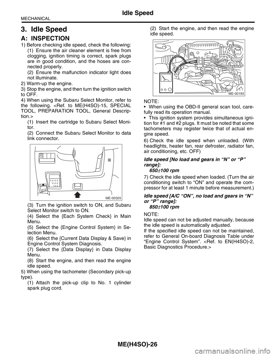
4) When using the Subaru Select Monitor, refer to
the following.
tion.>
(1) Insert the cartridge to Subaru Select Moni-
tor.
(2) Connect the Subaru Select Monitor to data
link connector.
(3) Turn the ignition switch to ON, and Subaru
Select Monitor switch to ON.
(4) Select the {Each System Check} in Main
Menu.
(5) Select the {Engine Control System} in Se-
lection Menu.
(6) Select the {Current Data Display & Save} in
Engine Control System Diagnosis.
(7) Select the {Data Display} in Data Display
Menu.
(8) Start the engine, and then read the engine
idle speed.
5) When using the tachometer (Secondary pick-up
type).
(1) Attach the pick-up clip to No. 1 cylinder
spark plug cord.(2) Start the engine, and then read the engine
idle speed.
NOTE:
When using the OBD-II general scan tool, care-
fully read its operation manual.
This ignition system provides simultaneous igni-
tion for #1 and #2 plugs. It must be noted that some
tachometers may register twice that of actual en-
gine speed.
6) Check the idle speed when unloaded. (With
headlights, heater fan, rear defroster, radiator fan,
air conditioning, etc. OFF)
Idle speed [No load and gears in “N” or “P”
range]:
650
±100 rpm
7) Check the idle speed when loaded. (Turn the air
conditioning switch to “ON” and operate the com-
pressor for at least 1 minute before measurement.)
Idle speed [A/C “ON”, no load and gears in “N”
or “P” range]:
850
±100 rpm
NOTE:
Idle speed can not be adjusted manually, because
the idle speed is automatically adjusted.
If the specified idle speed can not be maintained,
refer to General On-board Diagnosis Table under
“Engine Control System”.
ME-00325
ME-00193
Page 1037 of 2870

LU(H4SO)-9
LUBRICATION
Oil Pressure System
B: INSPECTION
Step Check Yes No
1 CHECK COMBINATION METER.
1) Turn the ignition switch to ON. (engine
OFF)
2) Check other warning lights.Does the warning lights illumi-
nate?Go to step 2.Repair or replace
the combination
meter.
Combination
Meter System.>
2 CHECK HARNESS CONNECTOR BETWEEN
COMBINATION METER AND OIL PRES-
SURE SWITCH.
1) Turn the ignition switch to OFF.
2) Disconnect the connector from oil pressure
switch.
3) Turn the ignition switch to ON.
4) Measure the voltage of harness between
the combination meter connector and chassis
ground.
Connector & terminal
(E11) No. 1 (+) — Chassis ground (
−):Is the voltage more than 10 V? Replace the oil
pressure switch.Go to step 3.
3 CHECK COMBINATION METER.
1) Turn the ignition switch to OFF.
2) Remove the combination meter.
3) Measure the resistance of combination
meter.
Te r m i n a l
No. B9 — No. A3:Is the resistance less than 10
Ω?Replace the har-
ness connector
between combina-
tion meter and oil
pressure switch.Repair or replace
the combination
meter and the oil
pressure switch
warning light bulb.
Page 1103 of 2870

EN(H4SO)-5
ENGINE (DIAGNOSTIC)
Check List for Interview
2. CHECK LIST No. 2
Check the following items about the vehicle’s state when malfunction indicator light turns on.
NOTE:
Use copies of this page for interviewing customers.
a) Other warning lights or indicators turn on. ❏ Yes / ❏ No
❏ Low fuel warning light
❏ Charge indicator light
❏ AT diagnostic indicator light
❏ ABS Warning light
❏ Oil pressure indicator light
b) Fuel level
Lack of gasoline: ❏ Yes / ❏ No
Indicator position of fuel gauge:
Experienced running out of fuel: ❏ Ye s / ❏ No
c) Intentional connecting or disconnecting of harness connectors or spark plug cords: ❏ Yes / ❏ No
What:
d) Intentional connecting or disconnecting of hoses: ❏ Ye s / ❏ No
What:
e) Installing of other parts except genuine parts: ❏ Ye s / ❏ No
What:
Where:
f) Occurrence of noise: ❏ Yes / ❏ No
From where:
What kind:
g) Occurrence of smell: ❏ Yes / ❏ No
From where:
What kind:
h) Intrusion of water into engine compartment or passenger compartment: ❏ Yes / ❏ No
i) Troubles occurred
❏ Engine does not start.
❏ Engine stalls during idling.
❏ Engine stalls while driving.
❏ Engine speed decreases.
❏ Engine speed does not decrease.
❏ Rough idling
❏ Poor acceleration
❏ Back fire
❏ After fire
❏ Does not shift.
❏ Excessive shift shock
Page 1304 of 2870

EN(H4SO)-206
ENGINE (DIAGNOSTIC)
Diagnostic Procedure with Diagnostic Trouble Code (DTC)
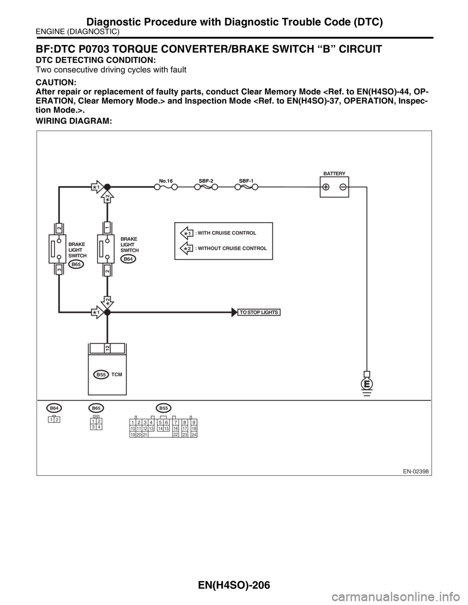
BF:DTC P0703 TORQUE CONVERTER/BRAKE SWITCH “B” CIRCUIT
DTC DETECTING CONDITION:
Two consecutive driving cycles with fault
CAUTION:
After repair or replacement of faulty parts, conduct Clear Memory Mode
WIRING DIAGRAM:
EN-02398
BATTERY
B65
34
12
TO STOP LIGHTS
SBF-1SBF-2No.16
B65 BRAKE
LIGHT
SWITCH
2
3
B64 BRAKE
LIGHT
SWITCH
1
B64
12
B55
B55
12
TCM
2
1
2
2
1
2
1: WITH CRUISE CONTROL
: WITHOUT CRUISE CONTROL
12
789 56 3410 11 12
19 20 2113 14 15 16 17 18
22
23
24
Page 1488 of 2870

ME(H4DOTC)-32
MECHANICAL
Idle Speed
3. Idle Speed
A: INSPECTION
1. USING SUBARU SELECT MONITOR
1) Before checking the idle speed, check the fol-
lowing:
(1) Ensure the air cleaner element is free from
clogging, ignition timing is correct, spark plugs
are in good condition, and that the hoses are
connected properly.
(2) Ensure the malfunction indicator light does
not illuminate.
2) Warm-up the engine.
3) Stop the engine, and then turn the ignition switch
to OFF.
4) Insert the cartridge to Subaru Select Monitor.
5) Connect the Subaru Select Monitor to data link
connector.
6) Turn the ignition switch to ON, and Subaru Se-
lect Monitor switch to ON.
7) Select the {2. Each System Check} in Main
Menu.
8) Select the {Engine Control System} in Selection
Menu.
9) Select the {1. Current Data Display & Save} in
Engine Control System Diagnosis.
10) Select the {1.12 Data Display} in Data Display
Menu.
11) Start the engine, and then read the engine idle
speed.
12) Check the idle speed when unloaded. (With
headlights, heater fan, rear defroster, radiator fan,
air conditioning, etc. OFF)
Idle speed [No load and gears in neutral]:
700
±100 rpm
13) Check the idle speed when loaded. (Turn the
air conditioning switch to “ON” and operate the
compressor for at least 1 minute before measure-
ment.)
Idle speed [A/C “ON”, no load and gears in neu-
tral]:
A/C Refrigerant pressure (LOW)
MT: 725
±100 rpm
AT: 750
±100 rpm
A/C Refrigerant pressure (HIGH)
MT: 800
±100 rpm
AT: 825
±100 rpm
NOTE:
As idle speed is controlled by the automatic adjust-
ment type, it can not be adjusted manually. If the
idle speed is out of specifications, refer to General
On-board Diagnosis Table under “Engine Control
System”.
Page 1635 of 2870

EN(H4DOTC)-5
ENGINE (DIAGNOSTIC)
Check List for Interview
2. CHECK LIST NO. 2
Check the following items about the vehicle’s state when malfunction indicator light turns on.
NOTE:
Use copies of this page for interviewing customers.
a) Other warning lights or indicators turn on. ❏ Yes / ❏ No
❏ Low fuel warning light
❏ Charge indicator light
❏ AT diagnostic indicator light
❏ ABS Warning Light
❏ Oil pressure indicator light
b) Fuel level
Lack of gasoline: ❏ Yes / ❏ No
Indicator position of fuel gauge:
Had run out of gas before: ❏ Ye s / ❏ No
c) Intentional connecting or disconnecting of harness connectors or spark plug cords: ❏ Yes / ❏ No
What:
d) Intentional connecting or disconnecting of hoses: ❏ Ye s / ❏ No
What:
e) Installing of other parts except genuine parts: ❏ Ye s / ❏ No
What:
Where:
f) Occurrence of noise: ❏ Yes / ❏ No
From where:
What kind:
g) Occurrence of smell: ❏ Yes / ❏ No
From where:
What kind:
h) Intrusion of water into engine compartment or passenger compartment: ❏ Yes / ❏ No
i) Troubles occurred
❏ Engine does not start.
❏ Engine stalls during idling.
❏ Engine stalls while driving.
❏ Engine speed decreases.
❏ Engine speed does not decrease.
❏ Rough idling
❏ Poor acceleration
❏ Back fire
❏ After fire
❏ Does not shift.
❏ Excessive shift shock