2004 SUBARU FORESTER display
[x] Cancel search: displayPage 620 of 2870

CC(H4DOTC 2.5)-8
CRUISE CONTROL SYSTEM (DIAGNOSTIC)
Subaru Select Monitor
5. Subaru Select Monitor
A: OPERATION
1. GENERAL
The on-board diagnosis function of the cruise con-
trol system uses the Subaru Select Monitor.
The on-board diagnosis function operates in two
categories, which are used depending on the type
of problems;
1) Cruise cancel conditions diagnosis:
(1) This category of diagnosis requires actual ve-
hicle driving in order to determine the cause, (as
when cruise speed is cancelled during driving al-
though cruise cancel condition is not entered).
(2) Cruise control memory of ECM stores the
cancel condition (Code No.) which occurred dur-
ing driving. When there are plural cancel condi-
tions (Code No.), they are shown on the Subaru
Select Monitor.
CAUTION:
The cruise control memory stores not only the
cruise “cancel” which occurred (although “can-
cel” operation is not entered by the driver), but
also the “cancel” condition input by the driver.
The content of memory is cleared when igni-
tion switch or cruise main switch is turned OFF.
2) Real-time diagnosis:
The real-time diagnosis function is used to deter-
mine whether or not the input signal system is in
good order, according to signal emitted from
switches, sensors, etc.
(1) Vehicle cannot be driven at cruise speed be-
cause problem occurs in the cruise control sys-
tem or its associated circuits.
(2) Monitor the signal conditions from switches
and sensors.
2. CRUISE CANCEL CONDITIONS DIAG-
NOSIS
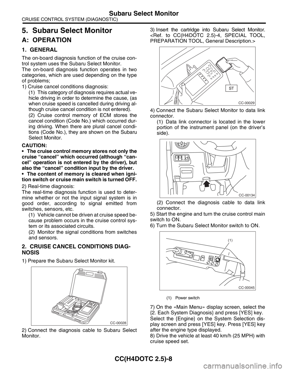
1) Prepare the Subaru Select Monitor kit.
2) Connect the diagnosis cable to Subaru Select
Monitor.3) Insert the cartridge into Subaru Select Monitor.
4) Connect the Subaru Select Monitor to data link
connector.
(1) Data link connector is located in the lower
portion of the instrument panel (on the driver’s
side).
(2) Connect the diagnosis cable to data link
connector.
5) Start the engine and turn the cruise control main
switch to ON.
6) Turn the Subaru Select Monitor switch to ON.
7) On the «Main Menu» display screen, select the
{2. Each System Diagnosis} and press [YES] key.
Select the {Engine} on the System Selection dis-
play screen and press [YES] key. Press [YES] key
after the engine type displayed.
8) Drive the vehicle at least 40 km/h (25 MPH) with
cruise speed set.
CC-00028
(1) Power switch
CC-00029
CC-00134
CC-00045
(1)
Page 621 of 2870

CC(H4DOTC 2.5)-9
CRUISE CONTROL SYSTEM (DIAGNOSTIC)
Subaru Select Monitor
9) If the cruise speed is canceled itself (without do-
ing any cancel operations), DTC will appear on se-
lect monitor display after {Cancel Code(s) Display}
is selected on the Engine Diagnosis display screen
and [YES] key is pressed.
CAUTION:
DTC will also appear when cruise cancel is ef-
fected by driver. Do not confuse.
Have a co-worker ride in the vehicle to assist
in diagnosis during driving.
NOTE:
DTC will be cleared by turning the ignition switch or
cruise control main switch to OFF.
3. REAL-TIME DIAGNOSIS
1) Connect the select monitor.
2) Turn the ignition switch and cruise control main
switch to ON.
3) Turn the Subaru Select Monitor switch to ON.
4) On the «Main Menu» display screen, select the
{2. Each System Check} and press [YES] key.
5) On the «System Selection» display screen, se-
lect the {Engine} and press [YES] key.
6) Press the [YES] key after the information of en-
gine type displayed.
7) On the «Engine Diagnosis» display screen, se-
lect the {Current Data Display & Save} and press
[YES] key.
8) Make sure that normal indication is displayed
when controls are operated as indicated below:
Depress/release the brake pedal. (Stop light
switch and brake switch turn ON.)
Turn ON the “SET/COAST” switch.
Turn ON the “RESUME/ACCEL” switch.
Turn ON the “CANCEL” switch. (The “SET/
COAST” and “RESUME/ACCEL” switch are turned
ON at same time.)
Depress/release the clutch pedal.
Set the shift lever to except for neutral position.
NOTE:
For detailed operation procedure, refer to the “SUB-
ARU SELECT MONITOR OPERATION MANUAL.”
For details concerning DTCs, refer to the “List of
Diagnostic Trouble Code (DTC).”
Code (DTC).>
Page 644 of 2870

IM-2
IMMOBILIZER (DIAGNOSTIC)
Basic Diagnostic Procedure
1. Basic Diagnostic Procedure
A: PROCEDURE
Step Check Yes No
1 CHECK ILLUMINATION OF IMMOBILIZER
WARNING LIGHT.
1) Turn the ignition switch to OFF or ACC
position.
2) Wait at least 60 seconds.Does the immobilizer warning
light blink?Go to step 2.Check the immobi-
lizer warning light
circuit.
IMMOBILIZER
WARNING CIR-
CUIT, INSPEC-
TION, Diagnostics
Chart for Immobi-
lizer Warning
Light.>
2 CHECK ILLUMINATION OF IMMOBILIZER
WARNING LIGHT.
Remove the key from ignition switch.Does the immobilizer warning
light begin to blink within 1 sec-
ond after the key is removed?Go to step 3.Check the key
switch circuit.
WARNING
SWITCH CIR-
CUIT, INSPEC-
TION, Diagnostics
Chart for Immobi-
lizer Warning
Light.>
3 CHECK ENGINE START.
Turn the ignition switch to START position.Does the engine start? Go to step 4.Go to step 5.
4 CHECK ILLUMINATION OF IMMOBILIZER
WARNING LIGHT.
Turn the ignition switch to ON.Does the immobilizer warning
light illuminate?Check the immobi-
lizer warning light
circuit.
IMMOBILIZER
WARNING CIR-
CUIT, INSPEC-
TION, Diagnostics
Chart for Immobi-
lizer Warning
Light.>Immobilizer sys-
tem is normal.
5 CHECK INDICATION OF DTC ON DISPLAY.
1) Turn the ignition switch to OFF.
2) Connect the Subaru Select Monitor to data
link connector.
3) Turn the ignition switch and Subaru Select
Monitors witch to ON.
4) Read any DTC on the display. Are DTCs indicated on dis-
play?Go to step 6.Repair the related
parts.
6 PERFORM THE DIAGNOSIS.
1) Inspect using “Diagnostics Chart with Trou-
ble Code”.
2) Repair the trouble cause.
3) Perform the clear memory mode.
4) Read any DTC again.Are DTCs indicated on dis-
play?Inspect using
“Diagnostic Proce-
dure with Diagnos-
tic Trouble Code
(DTC)”.
tics Procedure
with Diagnostic
Trouble Code
(DTC).>Finish the diag-
nostics.
Page 649 of 2870

IM-7
IMMOBILIZER (DIAGNOSTIC)
Subaru Select Monitor
5. Subaru Select Monitor
A: OPERATION
1. HOW TO USE SUBARU SELECT MONI-
TOR
1) Prepare the Subaru Select Monitor kit.
2) Connect the diagnosis cable to Subaru Select
Monitor.
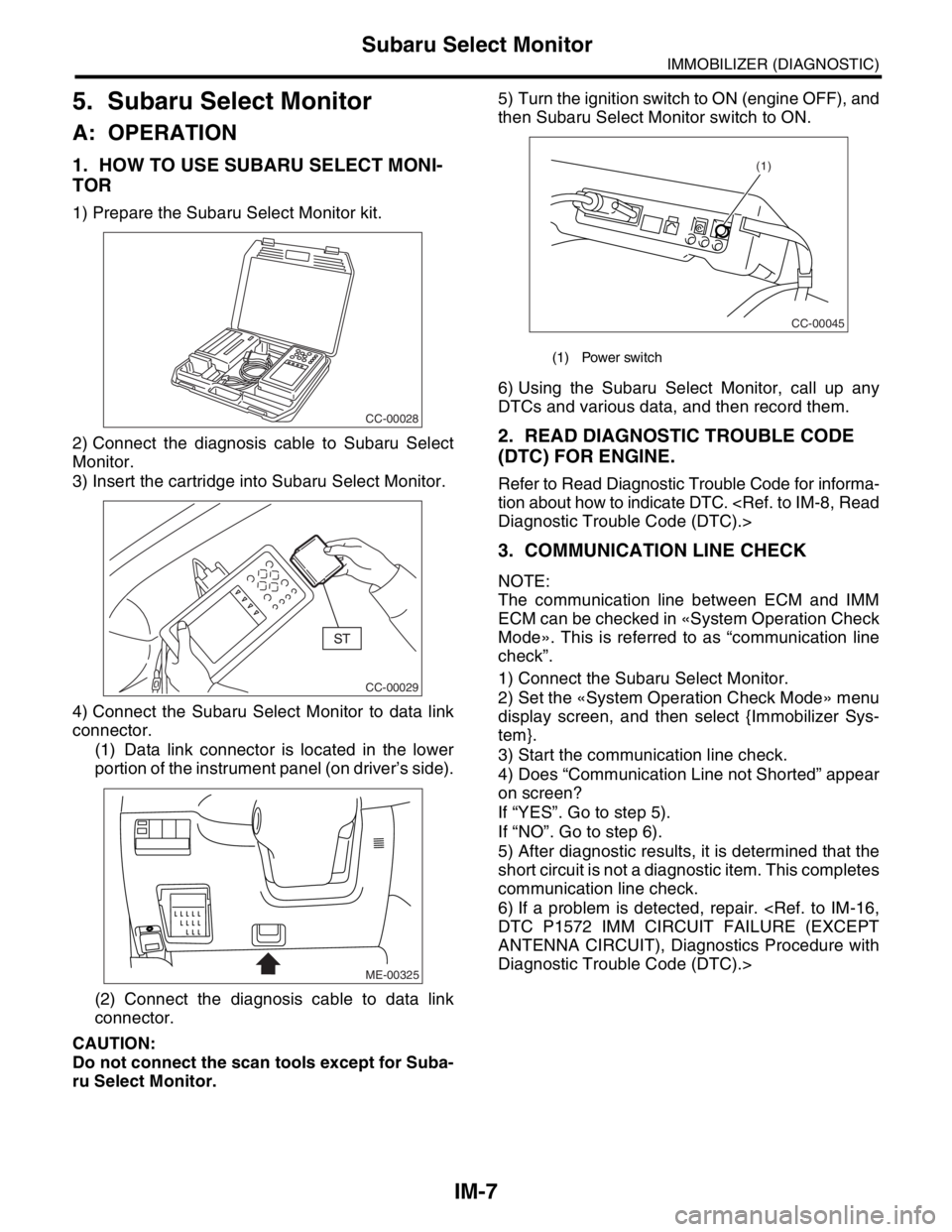
3) Insert the cartridge into Subaru Select Monitor.
4) Connect the Subaru Select Monitor to data link
connector.
(1) Data link connector is located in the lower
portion of the instrument panel (on driver’s side).
(2) Connect the diagnosis cable to data link
connector.
CAUTION:
Do not connect the scan tools except for Suba-
ru Select Monitor.5) Turn the ignition switch to ON (engine OFF), and
then Subaru Select Monitor switch to ON.
6) Using the Subaru Select Monitor, call up any
DTCs and various data, and then record them.
2. READ DIAGNOSTIC TROUBLE CODE
(DTC) FOR ENGINE.
Refer to Read Diagnostic Trouble Code for informa-
tion about how to indicate DTC.
3. COMMUNICATION LINE CHECK
NOTE:
The communication line between ECM and IMM
ECM can be checked in «System Operation Check
Mode». This is referred to as “communication line
check”.
1) Connect the Subaru Select Monitor.
2) Set the «System Operation Check Mode» menu
display screen, and then select {Immobilizer Sys-
tem}.
3) Start the communication line check.
4) Does “Communication Line not Shorted” appear
on screen?
If “YES”. Go to step 5).
If “NO”. Go to step 6).
5) After diagnostic results, it is determined that the
short circuit is not a diagnostic item. This completes
communication line check.
6) If a problem is detected, repair.
ANTENNA CIRCUIT), Diagnostics Procedure with
Diagnostic Trouble Code (DTC).>
CC-00028
CC-00029
ME-00325
(1) Power switch
CC-00045
(1)
Page 650 of 2870

IM-8
IMMOBILIZER (DIAGNOSTIC)
Read Diagnostic Trouble Code (DTC)
6. Read Diagnostic Trouble
Code (DTC)
A: OPERATION
1) On the «Main Menu» display screen, select the
{Each System Check}, and then press the [YES] key.
2) On the «System Selection Menu» display screen,
select the {Engine Control System}, and then press
the [YES] key.
3) Press the [YES] key after displayed information
of engine type.
4) On the «Engine Diagnosis» display screen, se-
lect the {Diagnostic Code(s) Display}, and then
press the [YES] key.
5) On the «Diagnostic Code(s) Display» display
screen, select the {Current Diagnostic Code(s)} or
{History Diagnostic Code(s)}, and then press the
[YES] key.
NOTE:
For detailed operation procedure, refer to the
SUBARU SELECT MONITOR OPERATION MAN-
UAL.
For detailed concerning diagnostic trouble codes,
refer to the List of Diagnostic Trouble Code (DTC).
Page 651 of 2870
![SUBARU FORESTER 2004 Service Repair Manual IM-9
IMMOBILIZER (DIAGNOSTIC)
Clear Memory Mode
7. Clear Memory Mode
A: OPERATION
1) On the «Main Menu» display screen, select the
{Each System Check}, and then press the [YES] key.
2) On the «Syst SUBARU FORESTER 2004 Service Repair Manual IM-9
IMMOBILIZER (DIAGNOSTIC)
Clear Memory Mode
7. Clear Memory Mode
A: OPERATION
1) On the «Main Menu» display screen, select the
{Each System Check}, and then press the [YES] key.
2) On the «Syst](/manual-img/17/57426/w960_57426-650.png)
IM-9
IMMOBILIZER (DIAGNOSTIC)
Clear Memory Mode
7. Clear Memory Mode
A: OPERATION
1) On the «Main Menu» display screen, select the
{Each System Check}, and then press the [YES] key.
2) On the «System Selection Menu» display screen,
select the {Engine Control System}, and then press the
[YES] key.
3) Press the [YES] key after displayed information
of engine type.
4) On the «Engine Diagnosis» display screen, se-
lect the {Clear Memory}, and then press the [YES]
key.
5) When the `Done’ is shown on the display screen,
turn the Subaru Select Monitor and ignition switch
to OFF.
NOTE:
After the memory has been cleared, the ISC must be
initialized.To do this, turn the ignition switch to ON po-
sition. Wait 3 seconds before starting the engine.
For detailed operation procedure, refer to the SUB-
ARUSELECT MONITOR OPERATION MANUAL.
Page 812 of 2870

FU(H4SO)-30
FUEL INJECTION (FUEL SYSTEM)
Throttle Position Sensor
(4) Tighten the throttle position sensor holding
screws.
Tightening torque:
1.6 N
⋅m (0.16 kgf-m, 1.2 ft-lb)
4) When using Subaru Select Monitor;
(1) Turn the ignition switch to OFF.
(2) Loosen the throttle position sensor holding
screws.
NOTE:
For detailed operation procedures, refer to the
SUBARU SELECT MONITOR OPERATION MAN-
UAL.
(3) Insert the cartridge to the Subaru Select
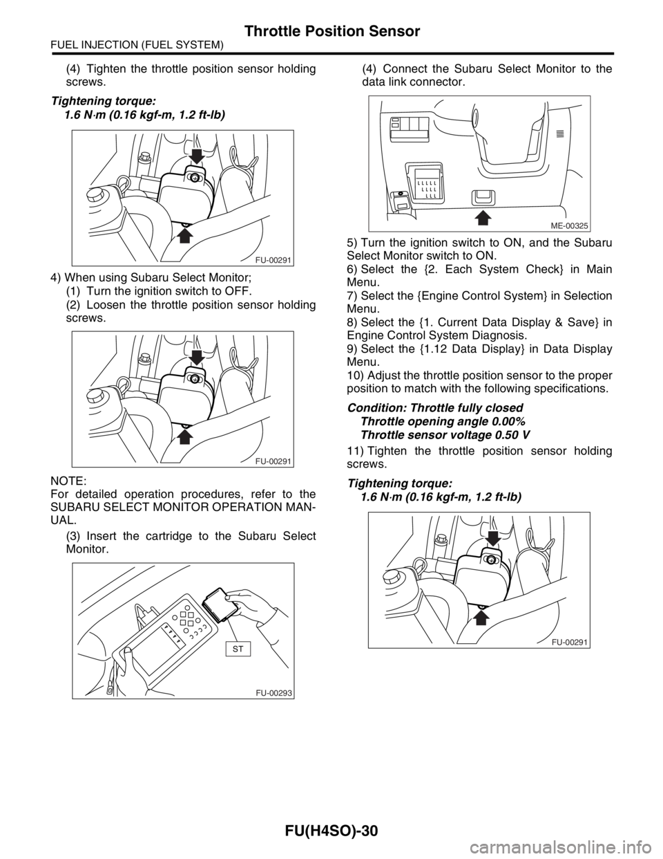
Monitor.(4) Connect the Subaru Select Monitor to the
data link connector.
5) Turn the ignition switch to ON, and the Subaru
Select Monitor switch to ON.
6) Select the {2. Each System Check} in Main
Menu.
7) Select the {Engine Control System} in Selection
Menu.
8) Select the {1. Current Data Display & Save} in
Engine Control System Diagnosis.
9) Select the {1.12 Data Display} in Data Display
Menu.
10) Adjust the throttle position sensor to the proper
position to match with the following specifications.
Condition: Throttle fully closed
Throttle opening angle 0.00%
Throttle sensor voltage 0.50 V
11) Tighten the throttle position sensor holding
screws.
Tightening torque:
1.6 N
⋅m (0.16 kgf-m, 1.2 ft-lb)
FU-00291
FU-00291
FU-00293
ST
ME-00325
FU-00291
Page 895 of 2870

ME(H4SO)-26
MECHANICAL
Idle Speed
3. Idle Speed
A: INSPECTION
1) Before checking idle speed, check the following:
(1) Ensure the air cleaner element is free from
clogging, ignition timing is correct, spark plugs
are in good condition, and the hoses are con-
nected properly.
(2) Ensure the malfunction indicator light does
not illuminate.
2) Warm-up the engine.
3) Stop the engine, and then turn the ignition switch
to OFF.
4) When using the Subaru Select Monitor, refer to
the following.
tion.>
(1) Insert the cartridge to Subaru Select Moni-
tor.
(2) Connect the Subaru Select Monitor to data
link connector.
(3) Turn the ignition switch to ON, and Subaru
Select Monitor switch to ON.
(4) Select the {Each System Check} in Main
Menu.
(5) Select the {Engine Control System} in Se-
lection Menu.
(6) Select the {Current Data Display & Save} in
Engine Control System Diagnosis.
(7) Select the {Data Display} in Data Display
Menu.
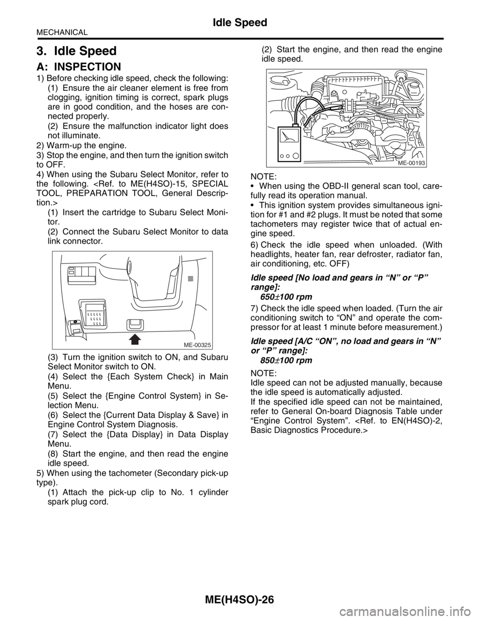
(8) Start the engine, and then read the engine
idle speed.
5) When using the tachometer (Secondary pick-up
type).
(1) Attach the pick-up clip to No. 1 cylinder
spark plug cord.(2) Start the engine, and then read the engine
idle speed.
NOTE:
When using the OBD-II general scan tool, care-
fully read its operation manual.
This ignition system provides simultaneous igni-
tion for #1 and #2 plugs. It must be noted that some
tachometers may register twice that of actual en-
gine speed.
6) Check the idle speed when unloaded. (With
headlights, heater fan, rear defroster, radiator fan,
air conditioning, etc. OFF)
Idle speed [No load and gears in “N” or “P”
range]:
650
±100 rpm
7) Check the idle speed when loaded. (Turn the air
conditioning switch to “ON” and operate the com-
pressor for at least 1 minute before measurement.)
Idle speed [A/C “ON”, no load and gears in “N”
or “P” range]:
850
±100 rpm
NOTE:
Idle speed can not be adjusted manually, because
the idle speed is automatically adjusted.
If the specified idle speed can not be maintained,
refer to General On-board Diagnosis Table under
“Engine Control System”.
ME-00325
ME-00193