Page 268 of 2870

LI-14
LIGHTING SYSTEM
Headlight Assembly
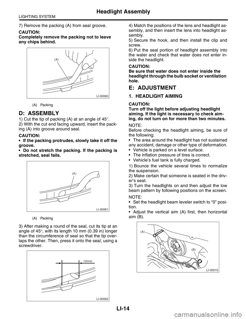
7) Remove the packing (A) from seal groove.
CAUTION:
Completely remove the packing not to leave
any chips behind.
D: ASSEMBLY
1) Cut the tip of packing (A) at an angle of 45°.
2) With the cut end facing upward, insert the pack-
ing (A) into groove around seal.
CAUTION:
If the packing protrudes, slowly take it off the
groove.
Do not stretch the packing. If the packing is
stretched, seal fails.
3) After making a round of the seal, cut its tip at an
angle of 45°, with its length 10 mm (0.39 in) longer
than the circumference of seal so that the tip over-
laps the other. Then, press it onto the seal, using a
screwdriver.4) Match the positions of the lens and headlight as-
sembly, and then insert the lens into headlight as-
sembly.
5) Secure the hook, and then install the clip and
screw.
6) Put the seal portion of headlight assembly into
the water and check that water does not enter in-
side the headlight.
CAUTION:
Be sure that water does not enter inside the
headlight through the bulb socket or ventilation
hole.
E: ADJUSTMENT
1. HEADLIGHT AIMING
CAUTION:
Turn off the light before adjusting headlight
aiming. If the light is necessary to check aim-
ing, do not turn on for more than two minutes.
NOTE:
Before checking the headlight aiming, be sure of
the following:
The area around the headlight has not sustained
any accident, damage or other type of deformation.
Vehicle is parked on a level surface.
The inflation pressure of tires is correct.
Vehicle’s fuel tank is fully charged.
1) Bounce the vehicle several times to normalize
the suspension.
2) Make certain that someone is seated in the driv-
er’s seat.
3) Turn the headlights on and then adjust the low
beam pattern by following positions on the screen.
NOTE:
Set the headlight beam leveler switch to “0” posi-
tion.
Adjust the vertical aim (A) first, then horizontal
aim (B).(A) Packing
(A) Packing
LI-00060
(A)
LI-00061
(A)
LI-00062
10mm
LI-00015
(A)
(B)
Page 269 of 2870
LI-15
LIGHTING SYSTEM
Headlight Assembly
This illustration is for LHD model. The pattern for RHD model is symmetrically opposite.
(A) Vehicle center (B) Bulb center
W mm (in) H mm (in) h mm (in) at 3 m (10 ft)
1,140 (44.88) 733 (28.9) 30 (1.18)
LI-00054
H
H W1
W
W W2
W2
W1 (A)
(A)
3m (10 ft)(B) h
h
Page 270 of 2870

LI-16
LIGHTING SYSTEM
Headlight Bulb
12.Headlight Bulb
A: REMOVAL
CAUTION:
Because the halogen bulb operates at a high
temperature, dirt and oil on the bulb surface re-
duces the bulb’s service life. Hold the flange
portion when replacing the bulb. Never touch
the glass portion.
Do not leave the headlight without a bulb for
a long time. Dust, moisture, etc. entering the
headlight may affect its performance.
1) Disconnect the ground cable from battery.
2) Remove the air intake duct (when removing the
headlight RH).
3) Disconnect the harness connector.
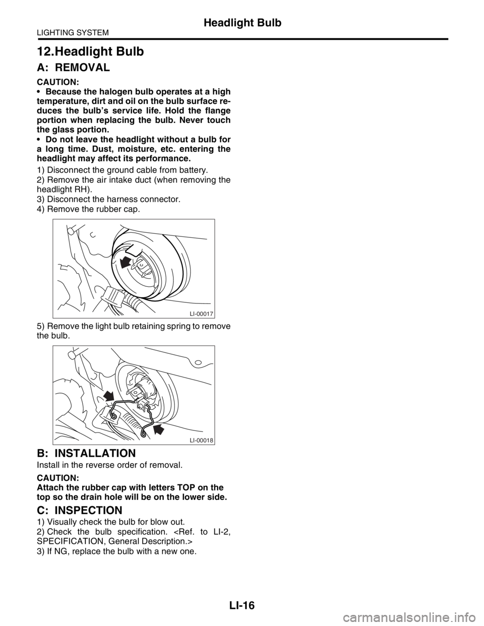
4) Remove the rubber cap.
5) Remove the light bulb retaining spring to remove
the bulb.
B: INSTALLATION
Install in the reverse order of removal.
CAUTION:
Attach the rubber cap with letters TOP on the
top so the drain hole will be on the lower side.
C: INSPECTION
1) Visually check the bulb for blow out.
2) Check the bulb specification.
SPECIFICATION, General Description.>
3) If NG, replace the bulb with a new one.
LI-00017
LI-00018
Page 271 of 2870
LI-17
LIGHTING SYSTEM
Front Turn Signal Light Bulb
13.Front Turn Signal Light Bulb
A: REMOVAL
1) Remove the headlight assembly.
REMOVAL, Headlight Assembly.>
2) Turn the socket and remove the bulb.
B: INSTALLATION
Install in the reverse order of removal.
C: INSPECTION
1) Visually check the bulb for blow out.
2) Check the bulb specification.
SPECIFICATION, General Description.>
3) If NG, replace the bulb with a new one.
LI-00021
Page 272 of 2870
LI-18
LIGHTING SYSTEM
Clearance Light Bulb
14.Clearance Light Bulb
A: REMOVAL
1) Remove the headlight assembly.
REMOVAL, Headlight Assembly.>
2) Turn the socket and remove the bulb.
B: INSTALLATION
Install in the reverse order of removal.
C: INSPECTION
1) Visually check the bulb for blow out.
2) Check the bulb specification.
SPECIFICATION, General Description.>
3) If NG, replace the bulb with a new one.
LI-00022
Page 274 of 2870
LI-20
LIGHTING SYSTEM
Front Fog Light Bulb
16.Front Fog Light Bulb
A: REMOVAL
1) Remove the front fog light assembly.
19, REMOVAL, Front Fog Light Assembly.>
2) Remove the back cover.
3) Remove the spring retainer, and then detach the
fog light bulb.
B: INSTALLATION
Install in the reverse order of removal.
C: INSPECTION
1) Visually check the bulb for blow out.
2) Check the bulb specification.
SPECIFICATION, General Description.>
3) If NG, replace the bulb with a new one.
LI-00026
LI-00027
Page 276 of 2870
LI-22
LIGHTING SYSTEM
Tail/Stop Light Bulb
18.Tail/Stop Light Bulb
A: REMOVAL
1) Remove the rear combination light assembly.
Assembly.>
2) Turn the socket and remove the bulb.
B: INSTALLATION
Install in the reverse order of removal.
C: INSPECTION
1) Visually check the bulb for blow out.
2) Check the bulb specification.
IFICATION, General Description.>
3) If NG, replace the bulb with a new one.
LI-00056
Page 277 of 2870
LI-23
LIGHTING SYSTEM
Back-up Light Bulb
19.Back-up Light Bulb
A: REMOVAL
1) Remove the rear combination light assembly.
Assembly.>
2) Turn the socket and remove the bulb.
B: INSTALLATION
Install in the reverse order of removal.
C: INSPECTION
1) Visually check the bulb for blow out.
2) Check the bulb specification.
IFICATION, General Description.>
3) If NG, replace the bulb with a new one.
LI-00032