2004 SUBARU FORESTER differential
[x] Cancel search: differentialPage 2768 of 2870
FUJI HEAVY INDUSTRIES LTD. G8080GE5
2004 FORESTER SERVICE MANUAL QUICK REFERENCE INDEX
TRANSMISSION SECTION
This service manual has been prepared
to provide SUBARU service personnel
with the necessary information and data
for the correct maintenance and repair
of SUBARU vehicles.
This manual includes the procedures
for maintenance, disassembling, reas-
sembling, inspection and adjustment of
components and diagnostics for guid-
ance of experienced mechanics.
Please peruse and utilize this manual
fully to ensure complete repair work for
satisfying our customers by keeping
their vehicle in optimum condition.
When replacement of parts during
repair work is needed, be sure to use
SUBARU genuine parts.
All information, illustration and specifi-
cations contained in this manual are
based on the latest product information
available at the time of publication
approval.CONTROL SYSTEM CS
AUTOMATIC TRANSMISSION 4AT
AUTOMATIC TRANSMISSION
(DIAGNOSTIC)4AT(H4SO)
AUTOMATIC TRANSMISSION
(DIAGNOSTIC)4AT(H4DOTC)
AUTOMATIC TRANSMISSION
(DIAGNOSTIC)4AT(H4DOTC 2.5)
MANUAL TRANSMISSION AND
DIFFERENTIAL5MT
CLUTCH SYSTEM CL
Page 2769 of 2870
5MT-56
MANUAL TRANSMISSION AND DIFFERENTIAL
Transfer Driven Gear
13.Transfer Driven Gear
A: REMOVAL
1) Remove the manual transmission assembly
from vehicle.
2) Remove the back-up light switch and neutral po-
sition switch.
3) Remove the transfer case with extension case
assembly.
4) Remove the extension case assembly.
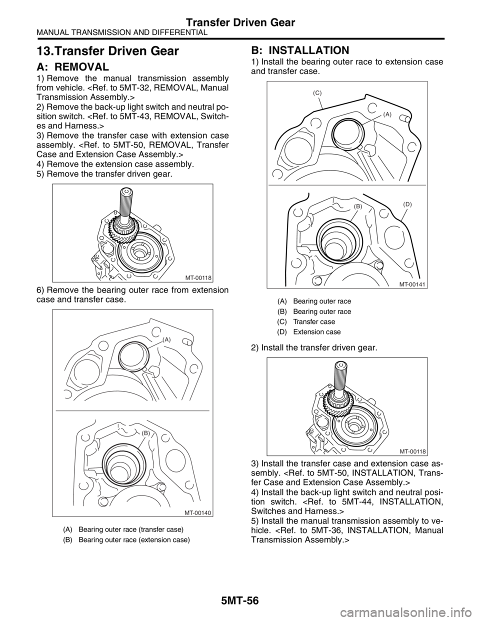
5) Remove the transfer driven gear.
6) Remove the bearing outer race from extension
case and transfer case.
B: INSTALLATION
1) Install the bearing outer race to extension case
and transfer case.
2) Install the transfer driven gear.
3) Install the transfer case and extension case as-
sembly.
4) Install the back-up light switch and neutral posi-
tion switch.
5) Install the manual transmission assembly to ve-
hicle.
(A) Bearing outer race (transfer case)
(B) Bearing outer race (extension case)
MT-00118
MT-00140 (B)
(A)
(A) Bearing outer race
(B) Bearing outer race
(C) Transfer case
(D) Extension case
(C)
(A)
(D)(B)
MT-00141
MT-00118
Page 2770 of 2870
5MT-57
MANUAL TRANSMISSION AND DIFFERENTIAL
Transfer Driven Gear
C: DISASSEMBLY
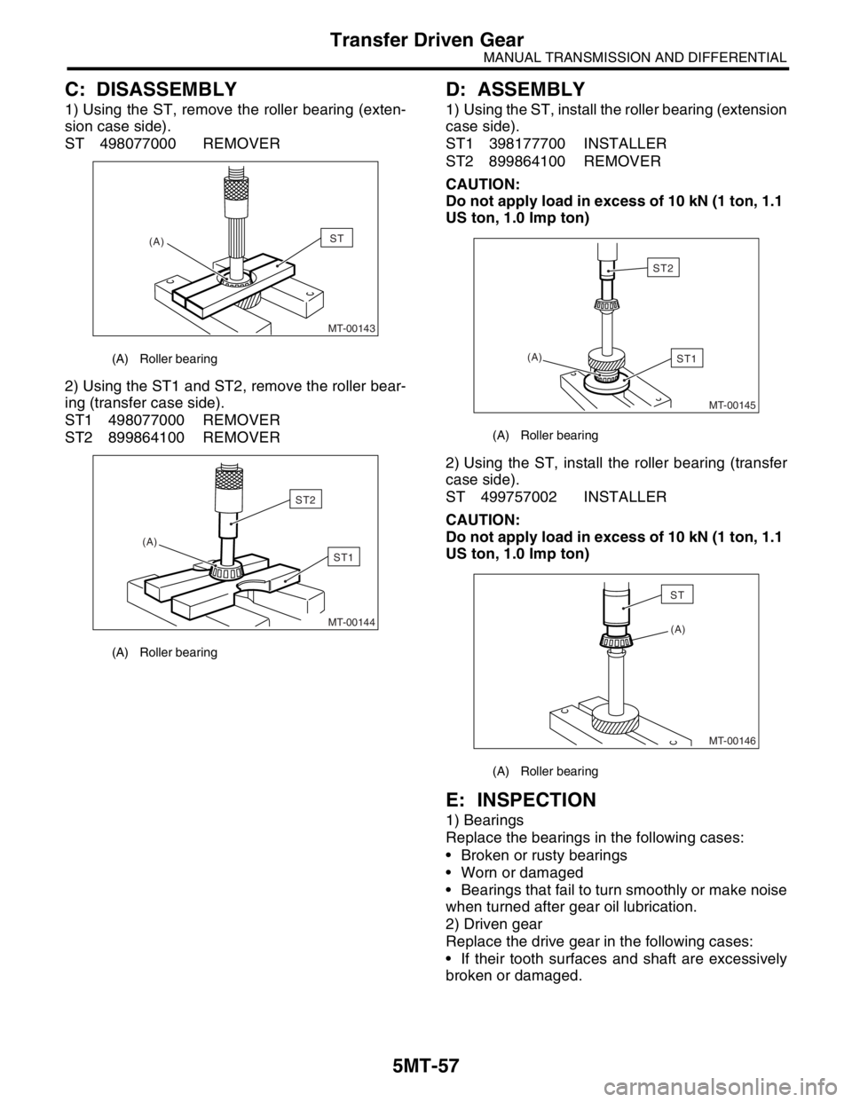
1) Using the ST, remove the roller bearing (exten-
sion case side).
ST 498077000 REMOVER
2) Using the ST1 and ST2, remove the roller bear-
ing (transfer case side).
ST1 498077000 REMOVER
ST2 899864100 REMOVER
D: ASSEMBLY
1) Using the ST, install the roller bearing (extension
case side).
ST1 398177700 INSTALLER
ST2 899864100 REMOVER
CAUTION:
Do not apply load in excess of 10 kN (1 ton, 1.1
US ton, 1.0 Imp ton)
2) Using the ST, install the roller bearing (transfer
case side).
ST 499757002 INSTALLER
CAUTION:
Do not apply load in excess of 10 kN (1 ton, 1.1
US ton, 1.0 Imp ton)
E: INSPECTION
1) Bearings
Replace the bearings in the following cases:
Broken or rusty bearings
Worn or damaged
Bearings that fail to turn smoothly or make noise
when turned after gear oil lubrication.
2) Driven gear
Replace the drive gear in the following cases:
If their tooth surfaces and shaft are excessively
broken or damaged.
(A) Roller bearing
(A) Roller bearing
MT-00143
(A)ST
MT-00144
(A)
ST1
ST2
(A) Roller bearing
(A) Roller bearing
MT-00145
(A)ST1
ST2
(A)
MT-00146
ST
Page 2771 of 2870
5MT-58
MANUAL TRANSMISSION AND DIFFERENTIAL
Center Differential
14.Center Differential
A: REMOVAL
1) Remove the manual transmission assembly
from vehicle.
2) Remove the transfer case with extension case
assembly.
3) Remove the extension case assembly.
Case Assembly.>
4) Remove the transfer driven gear.
5) Remove the center differential.
B: INSTALLATION
1) Install the center differential into transfer case.
2) Install the transfer driven gear.
3) Install the extension case assembly.
tension Case Assembly.>
4) Install the transfer case with extension case as-
sembly.
5) Install the back-up light switch and neutral posi-
tion switch.
6) Install the manual transmission assembly to ve-
hicle.
C: DISASSEMBLY
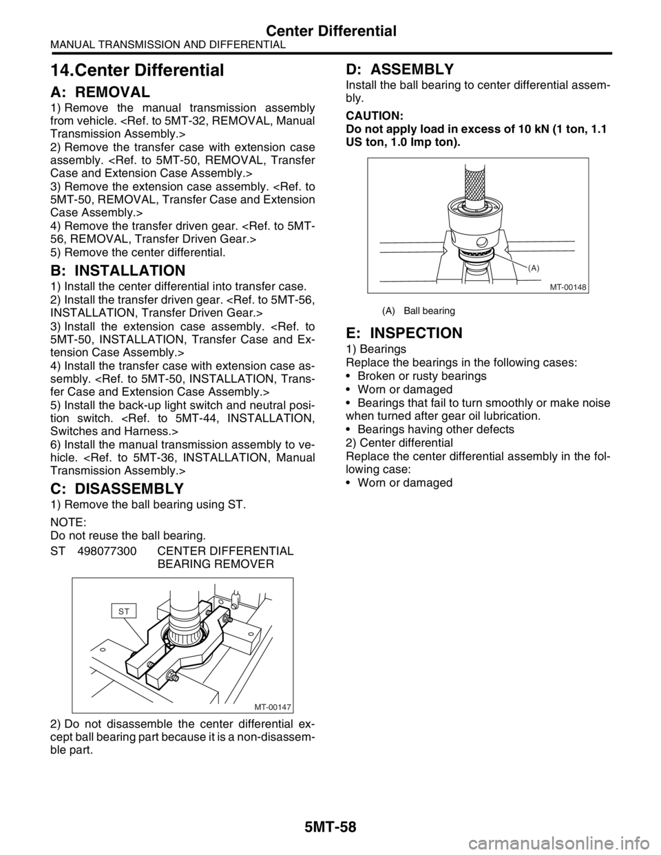
1) Remove the ball bearing using ST.
NOTE:
Do not reuse the ball bearing.
ST 498077300 CENTER DIFFERENTIAL
BEARING REMOVER
2) Do not disassemble the center differential ex-
cept ball bearing part because it is a non-disassem-
ble part.
D: ASSEMBLY
Install the ball bearing to center differential assem-
bly.
CAUTION:
Do not apply load in excess of 10 kN (1 ton, 1.1
US ton, 1.0 Imp ton).
E: INSPECTION
1) Bearings
Replace the bearings in the following cases:
Broken or rusty bearings
Worn or damaged
Bearings that fail to turn smoothly or make noise
when turned after gear oil lubrication.
Bearings having other defects
2) Center differential
Replace the center differential assembly in the fol-
lowing case:
Worn or damaged
MT-00147
ST
(A) Ball bearing
MT-00148 (A)
Page 2772 of 2870
5MT-59
MANUAL TRANSMISSION AND DIFFERENTIAL
Reverse Check Sleeve
15.Reverse Check Sleeve
A: REMOVAL
1) Remove the manual transmission assembly
from vehicle.
2) Remove the transfer case with extension case
assembly.
3) Remove the shifter arm.
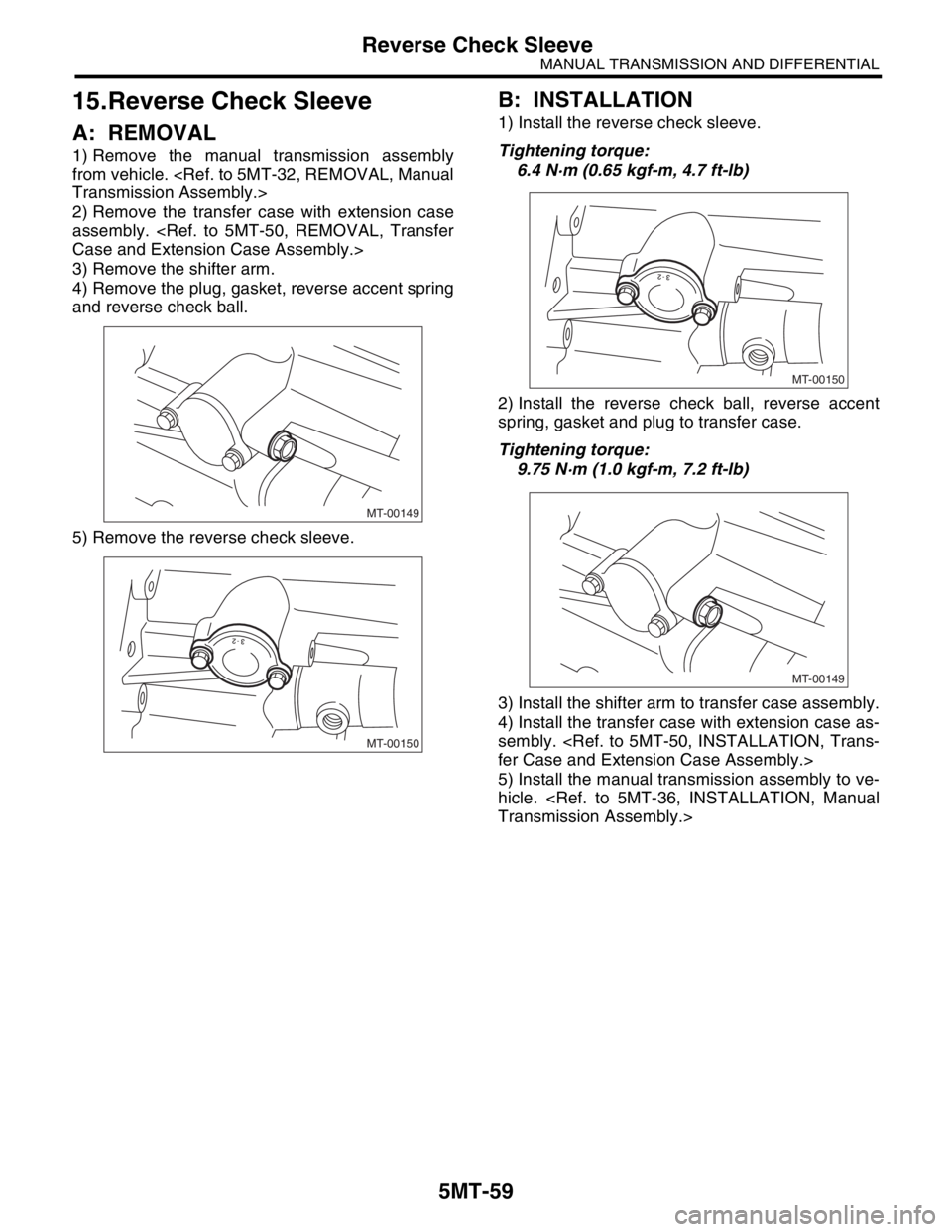
4) Remove the plug, gasket, reverse accent spring
and reverse check ball.
5) Remove the reverse check sleeve.
B: INSTALLATION
1) Install the reverse check sleeve.
Tightening torque:
6.4 N·m (0.65 kgf-m, 4.7 ft-lb)
2) Install the reverse check ball, reverse accent
spring, gasket and plug to transfer case.
Tightening torque:
9.75 N·m (1.0 kgf-m, 7.2 ft-lb)
3) Install the shifter arm to transfer case assembly.
4) Install the transfer case with extension case as-
sembly.
5) Install the manual transmission assembly to ve-
hicle.
MT-00149
MT-00150
MT-00150
MT-00149
Page 2773 of 2870
5MT-60
MANUAL TRANSMISSION AND DIFFERENTIAL
Reverse Check Sleeve
C: DISASSEMBLY
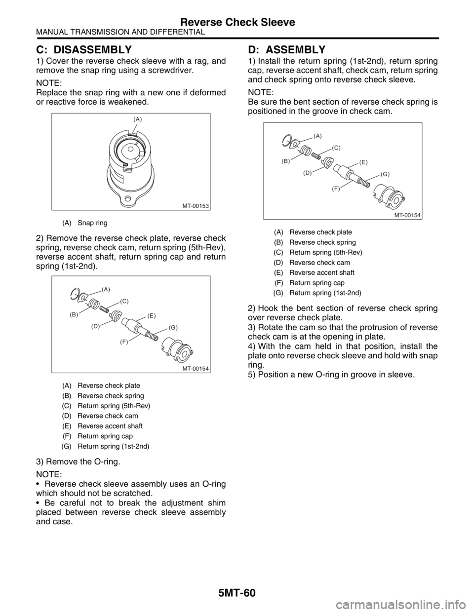
1) Cover the reverse check sleeve with a rag, and
remove the snap ring using a screwdriver.
NOTE:
Replace the snap ring with a new one if deformed
or reactive force is weakened.
2) Remove the reverse check plate, reverse check
spring, reverse check cam, return spring (5th-Rev),
reverse accent shaft, return spring cap and return
spring (1st-2nd).
3) Remove the O-ring.
NOTE:
Reverse check sleeve assembly uses an O-ring
which should not be scratched.
Be careful not to break the adjustment shim
placed between reverse check sleeve assembly
and case.
D: ASSEMBLY
1) Install the return spring (1st-2nd), return spring
cap, reverse accent shaft, check cam, return spring
and check spring onto reverse check sleeve.
NOTE:
Be sure the bent section of reverse check spring is
positioned in the groove in check cam.
2) Hook the bent section of reverse check spring
over reverse check plate.
3) Rotate the cam so that the protrusion of reverse
check cam is at the opening in plate.
4) With the cam held in that position, install the
plate onto reverse check sleeve and hold with snap
ring.
5) Position a new O-ring in groove in sleeve.
(A) Snap ring
(A) Reverse check plate
(B) Reverse check spring
(C) Return spring (5th-Rev)
(D) Reverse check cam
(E) Reverse accent shaft
(F) Return spring cap
(G) Return spring (1st-2nd)
MT-00153
(A)
MT-00154
(B)(C)
(D)(E)
(F)(G) (A)
(A) Reverse check plate
(B) Reverse check spring
(C) Return spring (5th-Rev)
(D) Reverse check cam
(E) Reverse accent shaft
(F) Return spring cap
(G) Return spring (1st-2nd)
MT-00154
(B)(C)
(D)(E)
(F)(G) (A)
Page 2774 of 2870
5MT-61
MANUAL TRANSMISSION AND DIFFERENTIAL
Reverse Check Sleeve
E: INSPECTION
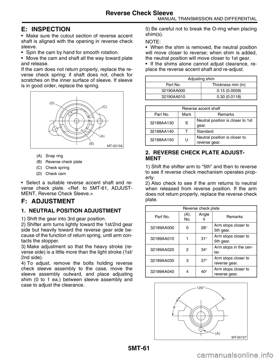
Make sure the cutout section of reverse accent
shaft is aligned with the opening in reverse check
sleeve.
Spin the cam by hand for smooth rotation.
Move the cam and shaft all the way toward plate
and release.
If the cam does not return properly, replace the re-
verse check spring; if shaft does not, check for
scratches on the inner surface of sleeve. If sleeve
is in good order, replace the spring.
Select a suitable reverse accent shaft and re-
verse check plate.
F: ADJUSTMENT
1. NEUTRAL POSITION ADJUSTMENT
1) Shift the gear into 3rd gear position.
2) Shifter arm turns lightly toward the 1st/2nd gear
side but heavily toward the reverse gear side be-
cause of the function of return spring, until arm con-
tacts the stopper.
3) Make adjustment so that the heavy stroke (re-
verse side) is a little more than the light stroke (1st/
2nd side).
4) To adjust, remove the bolts holding reverse
check sleeve assembly to the case, move the
sleeve assembly outward, and place adjusting
shim (0 to 1 ea.) between sleeve assembly and
case to adjust the clearance.5) Be careful not to break the O-ring when placing
shim(s).
NOTE:
When the shim is removed, the neutral position
will move closer to reverse; when shim is added,
the neutral position will move closer to 1st gear.
If the shims alone cannot adjust clearance, re-
place the reverse accent shaft and re-adjust.
2. REVERSE CHECK PLATE ADJUST-
MENT
1) Shift the shifter arm to “5th” and then to reverse
to see if reverse check mechanism operates prop-
erly.
2) Also check to see if the arm returns to neutral
when released from reverse position. If the arm
does not return properly, replace the reverse check
plate.
(A) Snap ring
(B) Reverse check plate
(C) Check spring
(D) Check cam
MT-00156
(A) (D)
(B)(C)
Adjusting shim
Part No. Thickness mm (in)
32190AA000 0.15 (0.0059)
32190AA010 0.30 (0.0118)
Reverse accent shaft
Part No. Mark Remarks
32188AA130 SNeutral position is closer to 1st
gear.
32188AA140 T Standard
32188AA150 UNeutral position is closer to
reverse gear.
Reverse check plate
Par t No.(A):
No.Angle
θRemarks
32189AA000 0 28°Arm stops closer to
5th gear.
32189AA010 1 31°Arm stops closer to
5th gear.
32189AA020 2 34°Arm stops in the cen-
ter.
32189AA030 3 37°Arm stops closer to
reverse gear.
32189AA040 4 40°Arm stops closer to
reverse gear.
MT-00157(A)
Page 2775 of 2870
5MT-62
MANUAL TRANSMISSION AND DIFFERENTIAL
Transmission Case
16.Transmission Case
A: REMOVAL
1. SINGLE-RANGE
1) Remove the manual transmission assembly
from vehicle.
2) Remove the clutch release lever.
3) Remove the transfer case with extension case
assembly.
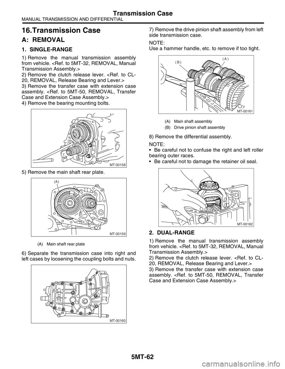
4) Remove the bearing mounting bolts.
5) Remove the main shaft rear plate.
6) Separate the transmission case into right and
left cases by loosening the coupling bolts and nuts.7) Remove the drive pinion shaft assembly from left
side transmission case.
NOTE:
Use a hammer handle, etc. to remove if too tight.
8) Remove the differential assembly.
NOTE:
Be careful not to confuse the right and left roller
bearing outer races.
Be careful not to damage the retainer oil seal.
2. DUAL-RANGE
1) Remove the manual transmission assembly
from vehicle.
2) Remove the clutch release lever.
3) Remove the transfer case with extension case
assembly.
MT-00158
MT-00159
(A)
MT-00160
(A) Main shaft assembly
(B) Drive pinion shaft assembly
MT-00161
(A)
(B)
MT-00162